-
Where Have I been?
04/06/2021 at 19:58 • 0 commentsWell....
[sweeps away cobebs from this page]
...its been a while since I showed my face here. Since my last post however its been bedlam!
Redunancy, new jobs, moving house, COVID, furlough, its all been happening.
But, now that everything has settled down a bit, I have now returned with some new projects in mind...
-
Getting started with Bluetooth-ing your project
07/26/2019 at 20:15 • 0 commentsUpdate I wanted to share. I was able to make a simple LED light on and off at the tap of a button on my phone. Not the most ground breaking development, but it though I'd share the information for those looking to start.
![]()
I've been following the tutorials here:
- http://www.martyncurrey.com/arduino-and-hc-06-zs-040/
- http://www.martyncurrey.com/android-mit-app-inventor-auto-connect-to-bluetooth/
and using the MIT AppInventor:
The appInventor is a great introduction to those who are pretty new to app development. The way you upload your apps to your phone is pretty clever too, all you need to the is download the MIT AI2 Companion app and enter a code for your app. It is advised you go through the getting started tutorial first, its quite painless. You will need an andriod phone, sorry iPhone users.
There is code supplied with the instructions on Martyn Currey's website as well as a file you can upload to your AppInvetor account.
You'll have to have a close read of Martyn's explanation of the code in appInventor whilst reading the code in the appInventor in order to expand your understanding what bit is doing what.
Anyway its a good starting point for those looking to get started on bluetooth-ing their project.
Guess the next step is reading values to the phone...
-
1 Hour Hack: Internal light for Landy
11/06/2017 at 23:20 • 0 commentsi won't lie: the amount of crap that floating around my landrover is shameful at worse. However, something that was flaoting in my passenger footwell got me thinking...
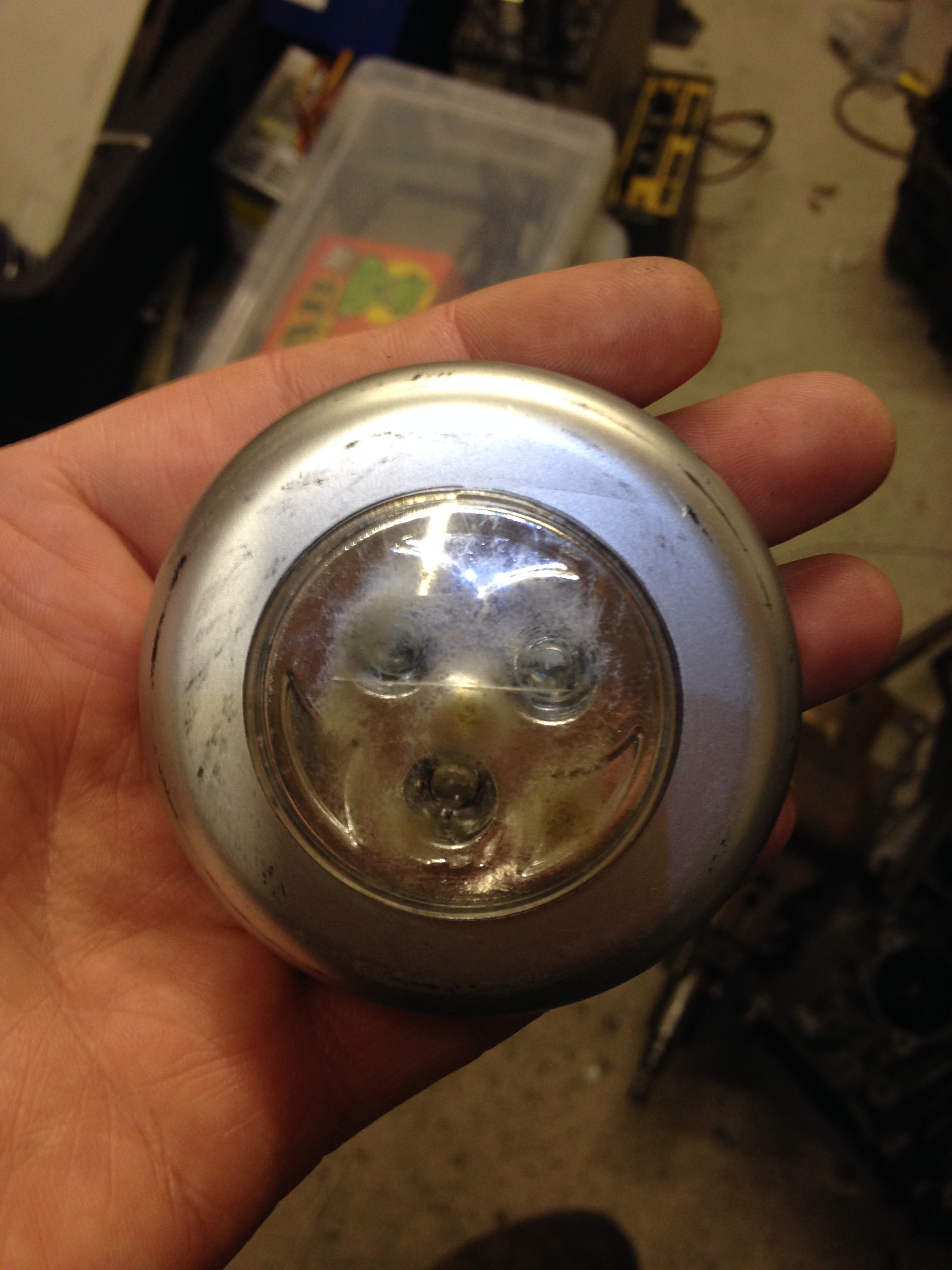
Yep its one of those crappy pound-land (dollar-store for you yanks) LED cabinate lights from a previously failed attempt of having some internal lighting by using the sticky pads that are fitted to them. The ride in the Landrover is not that great, even on a smooth road its bumpy as hell! so they just kept falling don off the sunvisors.
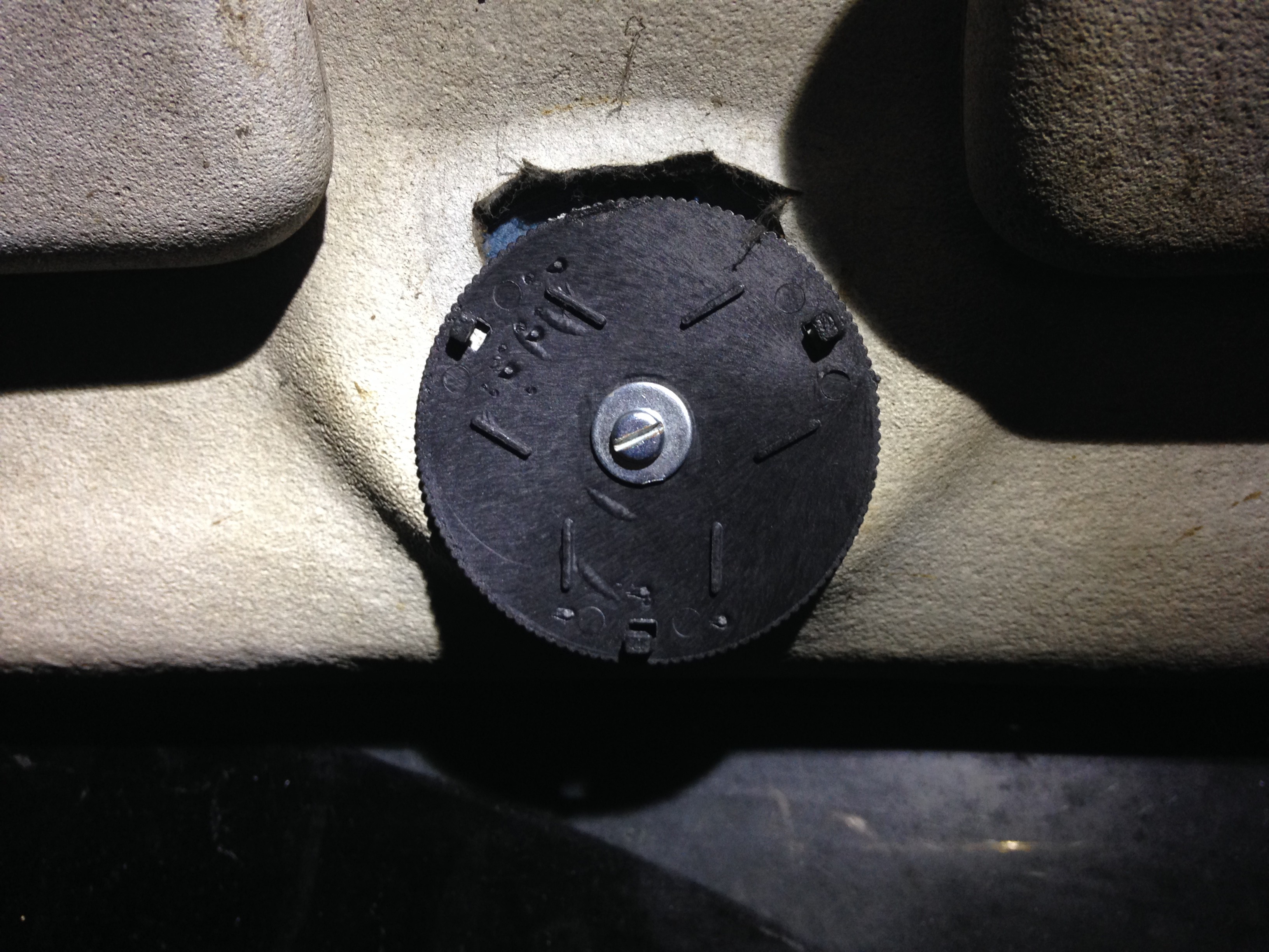
However I have no rear view mirror, no point in fitting one as all I'll see is the scaffolding of the rollcage! There are still the screw holes above the windscreen for a mirror, which are M3 thread.
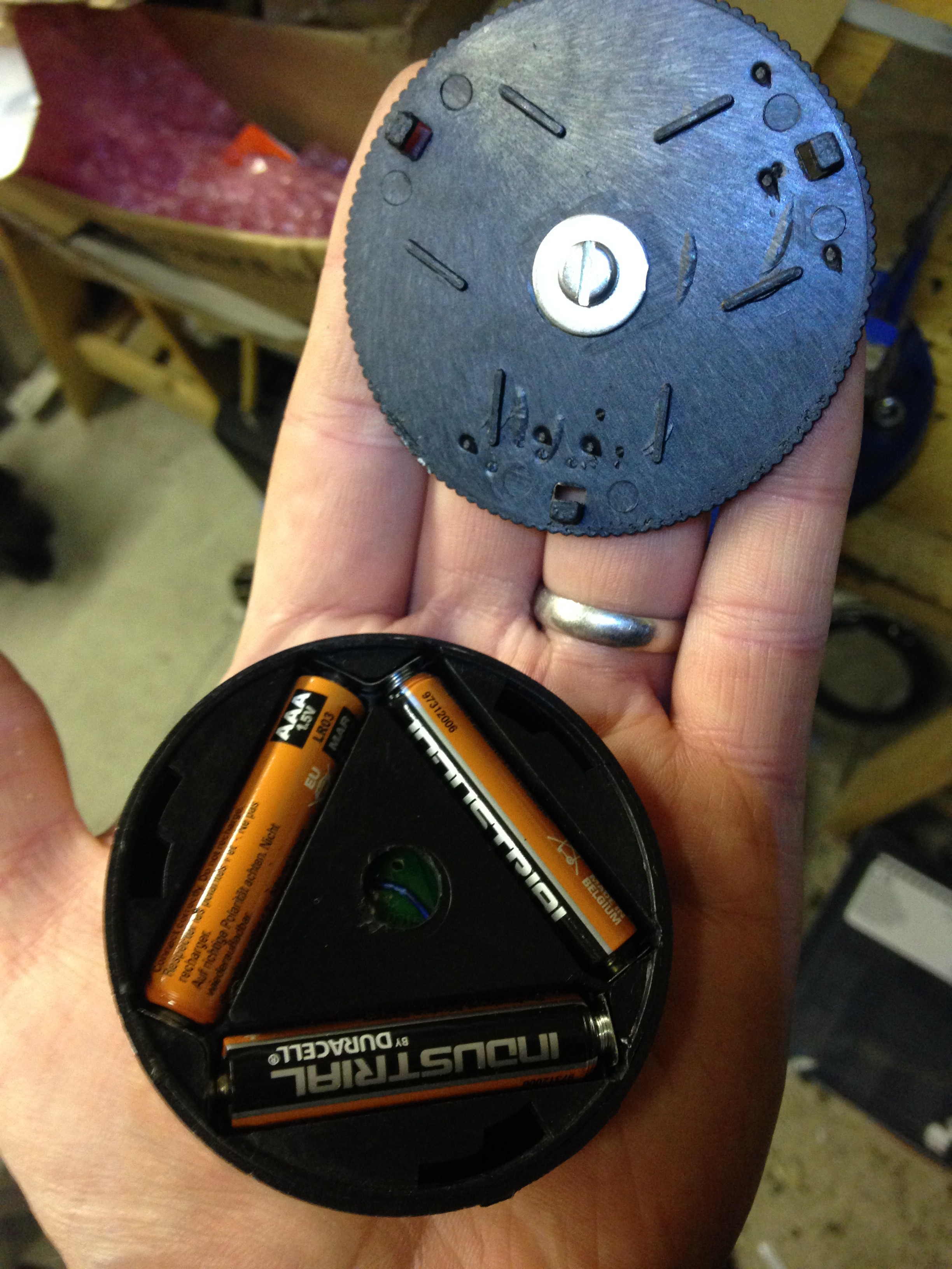
I took the back off the light and stuck some batteries in to check it worked first, then remove the woefully inadequate adhesive off the back, refitted the back plate and drilled a 3.5mm hole in the back for an M3 screw. This also marked the inside to drill a larger hole for the head of the bolt to fit into, albeit exposing the circuit board inside.
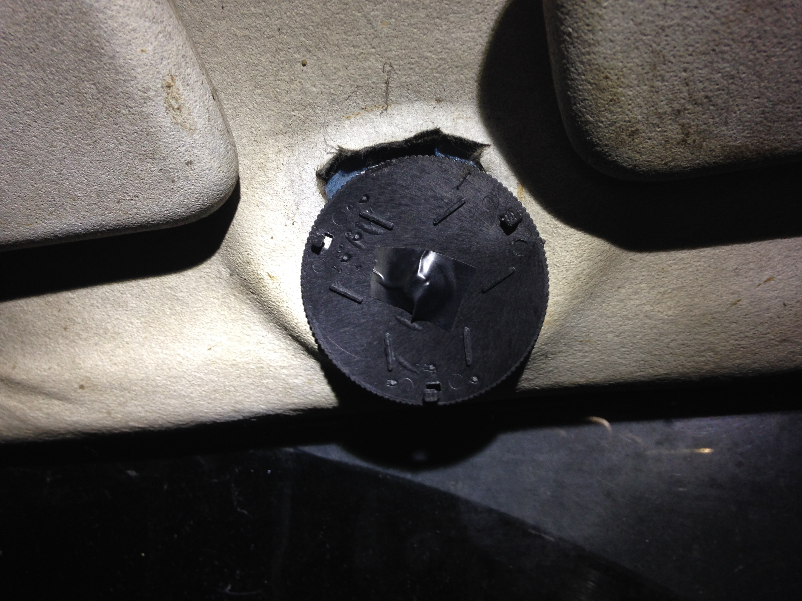
Hardware in place, I then fitted it to the mounting screws in the landrover above the windscreen, then applied some insulation tape of the head of the screw as not to accidentally short out the traces on the PCB:
Then it was just a case of refitting the LED light onto it and testing:
VIOLA! quick tap and light, also not reliant on vehicles battery power, which is sometimes the case when I'm working on the electrical systems.
Took less than an hour and all out of junk parts!
-
The Thurlby Complex
08/13/2017 at 19:42 • 0 commentsGather round folks and I will spin a yarn of confusion.
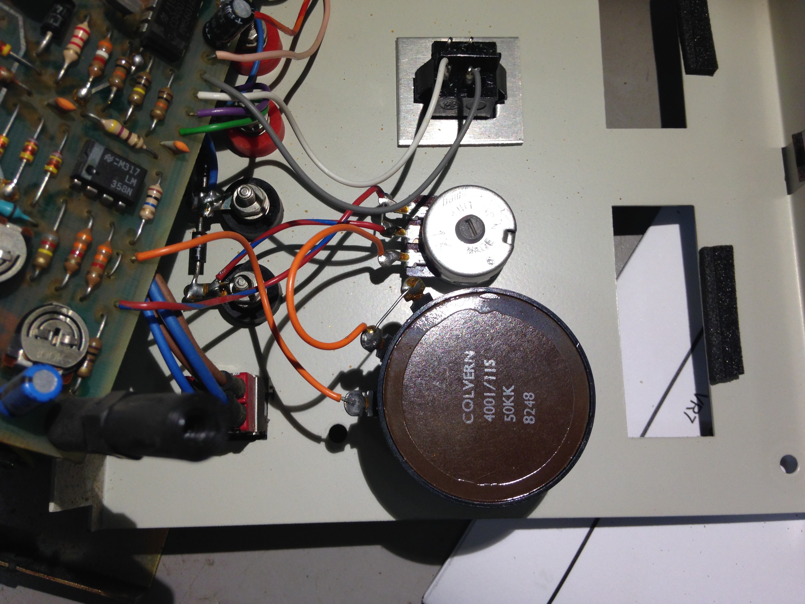
So I acquired a Thurlby PL310 PSU (least that's what it said on the front) a while ago. It had an issue where the voltage adjustment at the low end (0-3V) was very jumpy:
Although useable, I decided after a while that I should really get round to fixing this. A quick Google relieved a few others who had suffered the same problem with a common fix: Replace the old wire wound coarse adjustment pot with a new, better, carbon track one. And whilst your at it replace the fine adjustment one.
There was a pretty google hit of somebody who had posted pics of their repair that was on a site which had not been maintained/dues paid, but can't seem to get the same hits from the same search terms anymore...
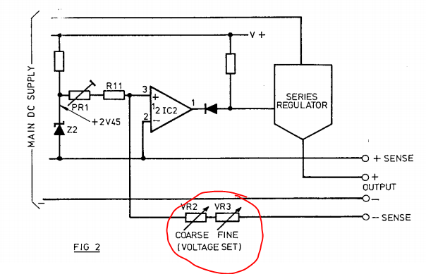
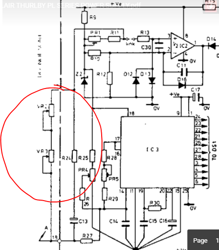
I also read that the voltage adjustment pots were not wired as you would typically expect in a linear PSU. They appeared to be part of a feedback network and being used a variable resistors/rheostats rather than potentiometers changing the set point.
I've a copy of the service manual here if anyone wants it: SINCLAIR THURLBY PL SERIES POWER SUPPLY
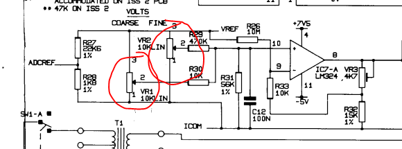
Now if you look at the Thandar range of PL series power supplies you will find that the pots are wired as pots:
Also IC7-A is an LM324....which I couldn't find:
No LM324 here! So massive pitfall there! Turns out the Sinclair branded and Thandar branded PSU, SHARE THE SAME MODEL NUMBER!! But why the flipping hell did Thurlby do this!?!
"I know! New company structure, New PSU design, Lets name it EXACTLY the same as the old product!!"
...yeh well done chaps...could have at least bloody versioned it!
Anyway, massive model number flaws aside, this was a distraction from the task at hand, but I though I should make the uninitiated aware.
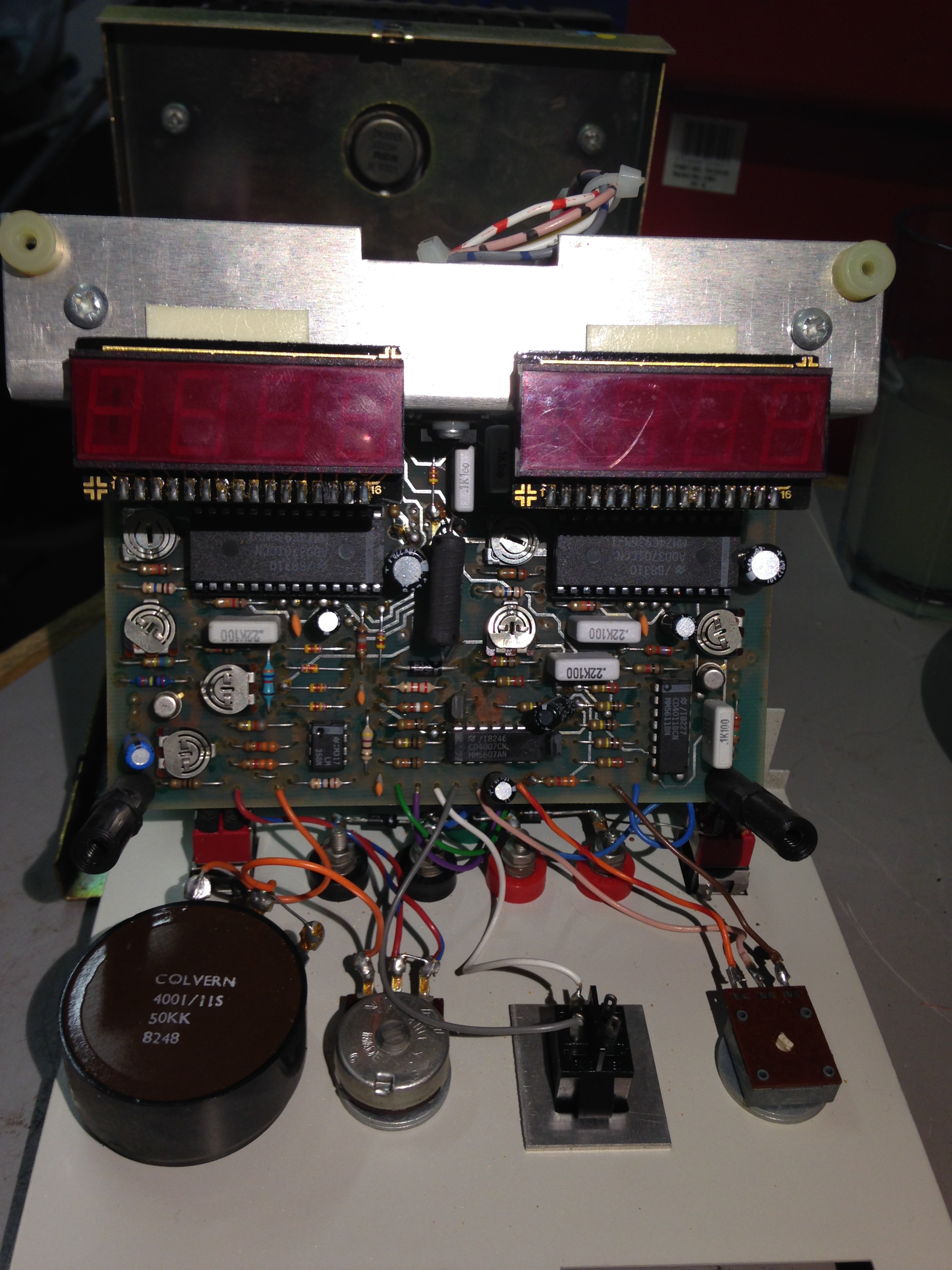
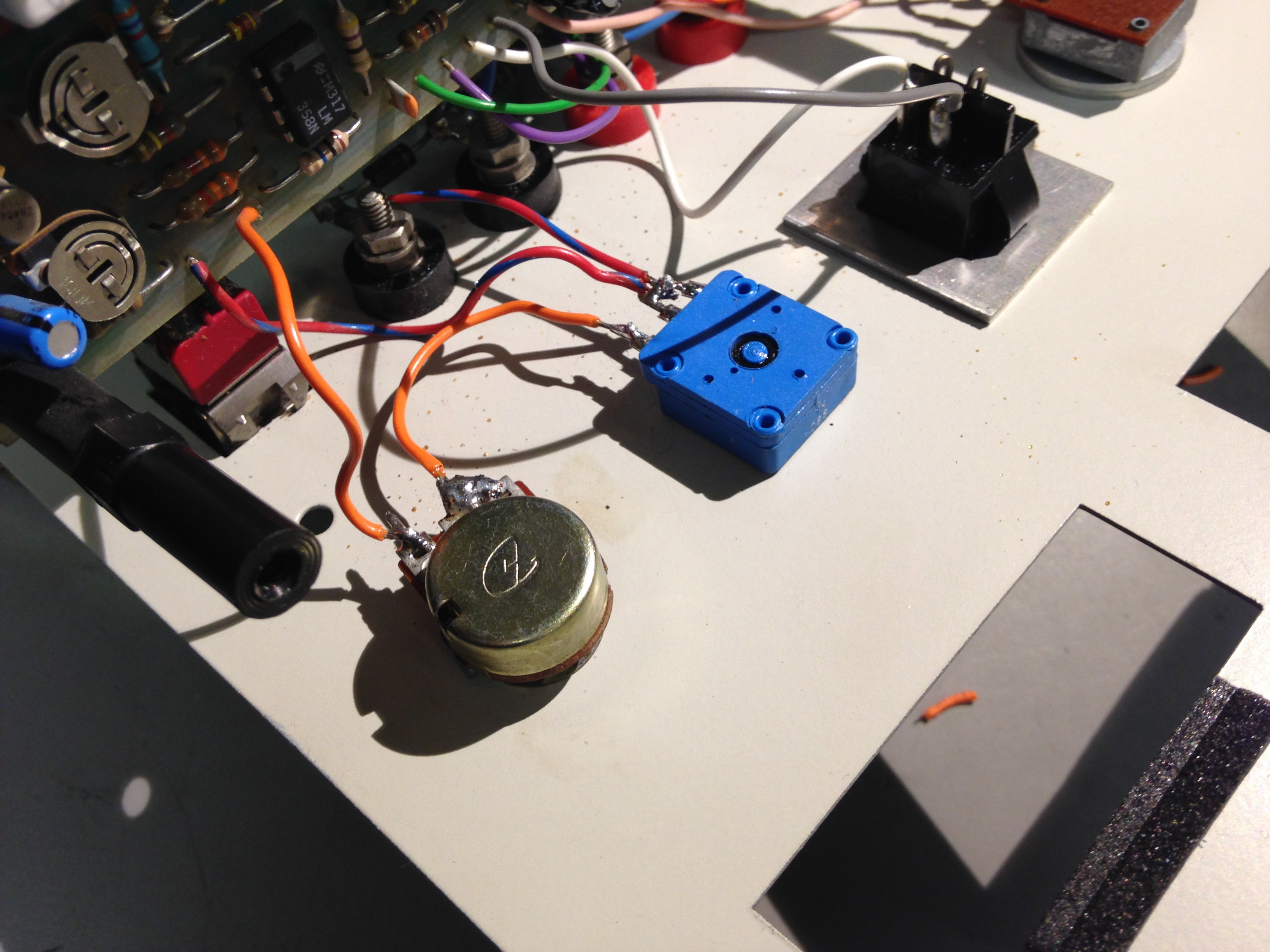
The task at hand was to replace the potentiometers:
Rummage in the spares box and a 50k pot (coarse) and 1k pot (fine) were acquired.
After fitting them and giving them a little test, the voltage was stable and the fluctuating output had gone completely.
It should be noted as well that if you're testing this after fitting new pots, and you are resting the front panel PCB near the AC line switch, you will see the same fault you are trying to cure! Seems the Mains interference is large enough to cause the same issue.
-
Upgrading a Kiethley 177 DMM's Input Jacks
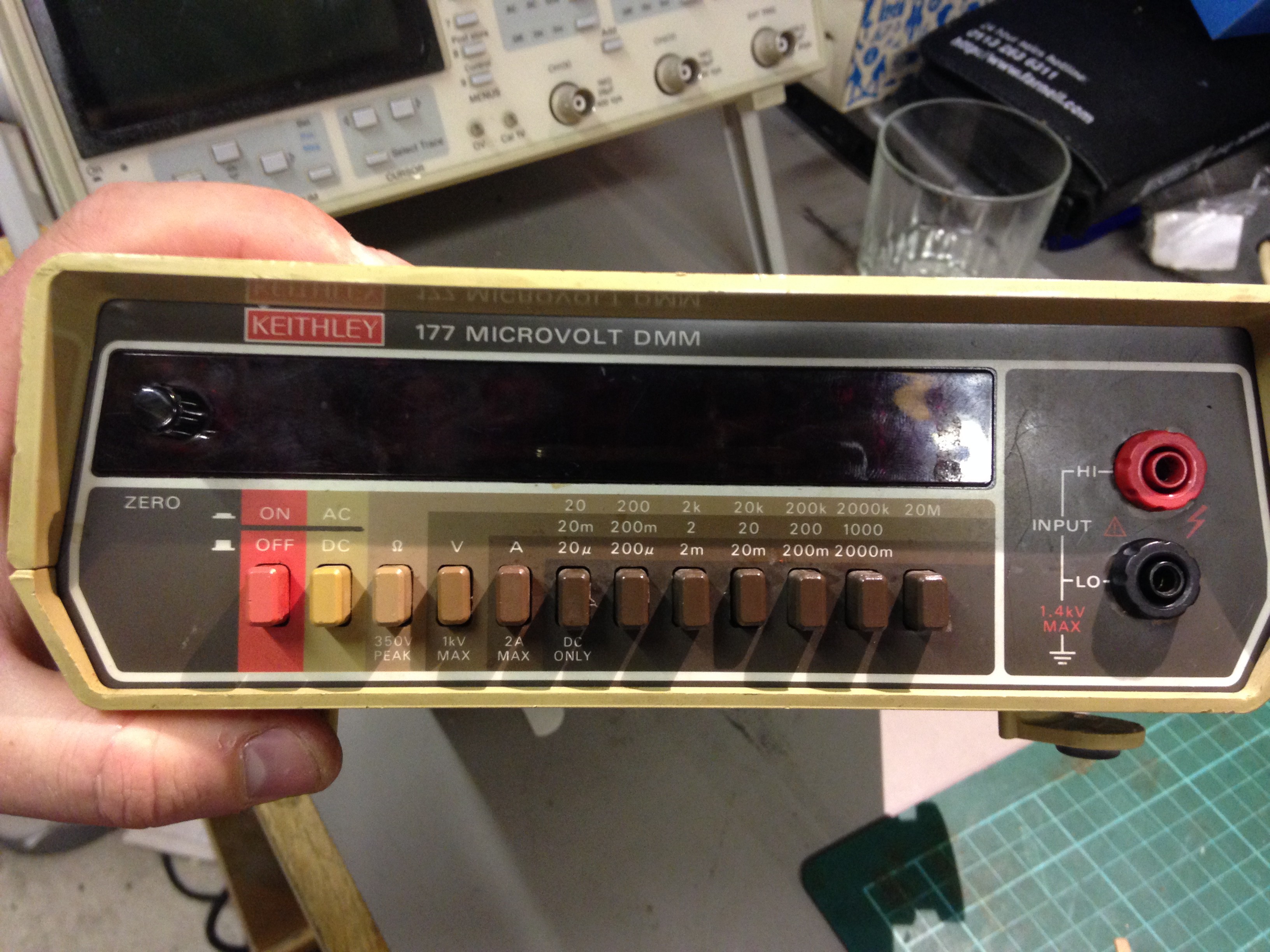
08/03/2017 at 12:47 • 0 commentsI recently scored a 177 DMM from a dumpster dive, they aren't a bad meter! 4.5 digit, 2000 count, 20mV range with 10uV resolution & 20uA range with 1nA resolution, for something built in the 70's is not bad!
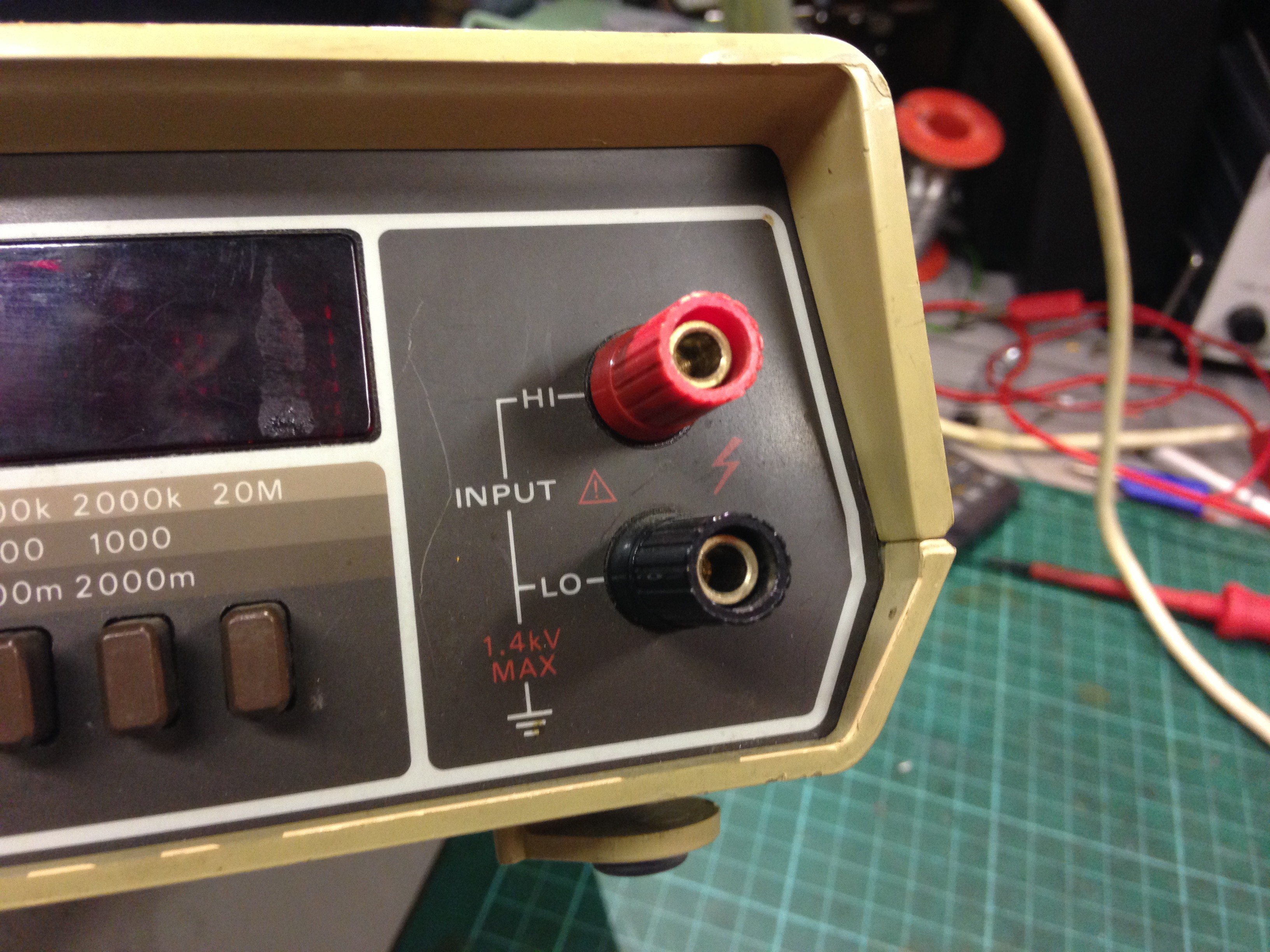
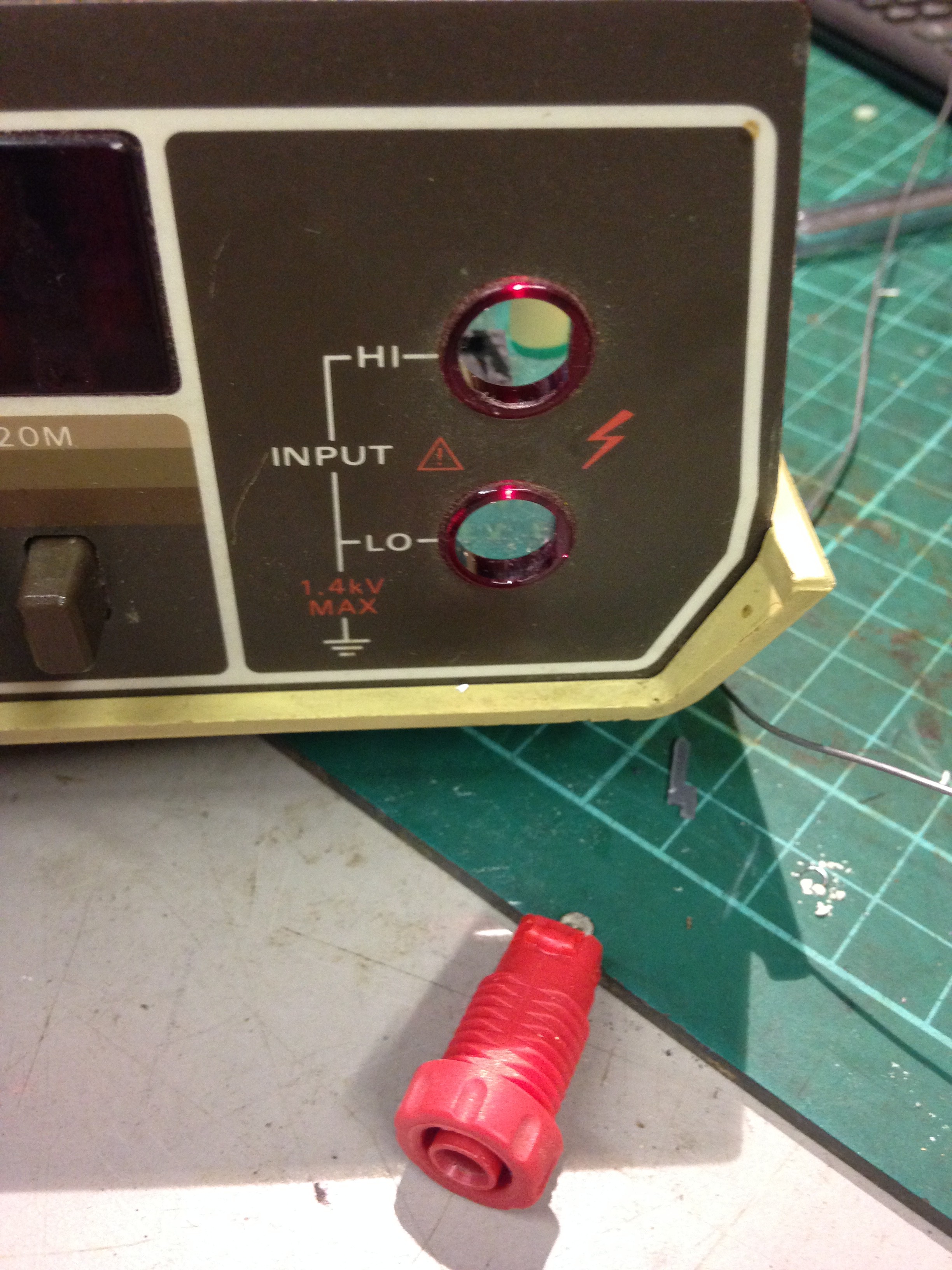
However I'm not too keen on the input jacks:
They are made of some quality metal, but most modern probes now have the shrouded jacks, which don't fit these posts and I don't want to hack up my probes.
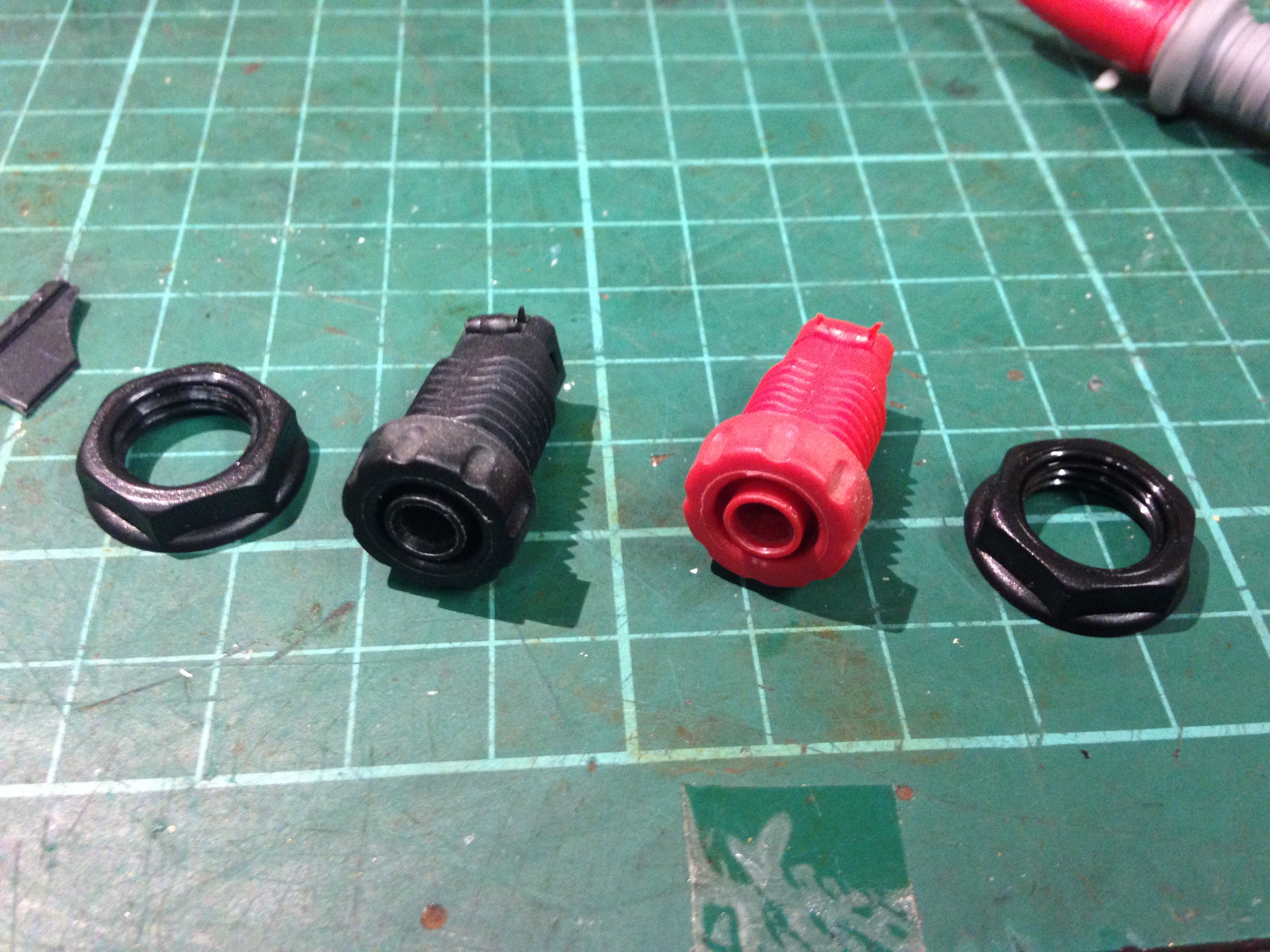
So I found an old 3.5 Blackstar DMM and stole the jacks out of that:
I then removed the posts off the Keithley:
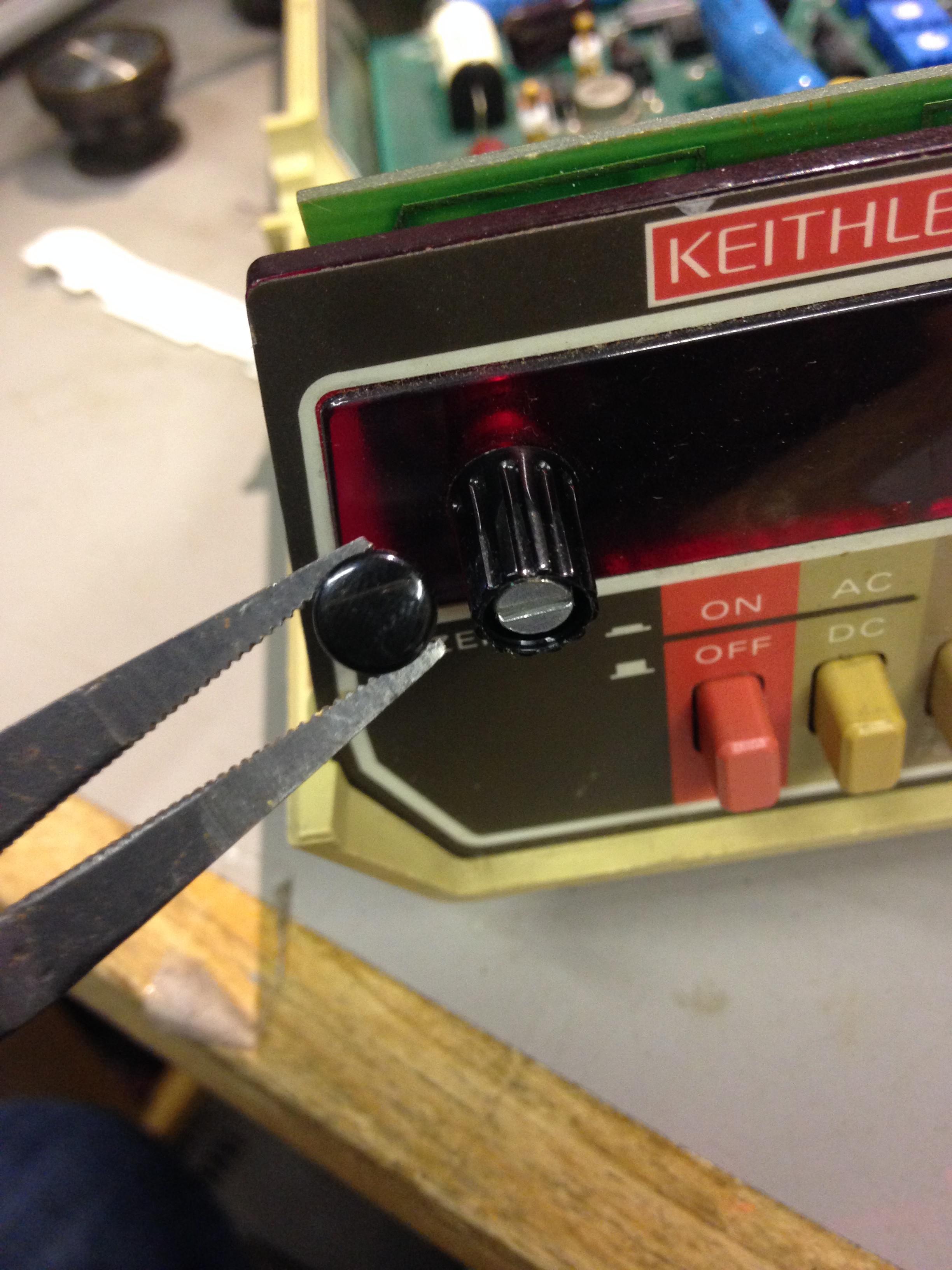
The existing holes were too small for the new posts, so I removed the whole front plate off so I could work on it without damaging the DMM internals. This meant removing the zeroing knob on the side of the display. This was done by popping the top off the know and unscrewing the screw a little to free it of the spindle:
Whilst I had the plate off I thought i might be a good idea the stencil it out onto paper for reference just in case I broke it during drilling and maybe later CAD it out in DXF format so new ones can be laser cut if anyone needed one.
After drilling the holes out I then fitted the new posts:
And then fitted the panel and knob back onto the DMM:
Now I can use my modern probes with it!
-
Trio SSVM Model T-104 Inspection
06/18/2017 at 21:23 • 0 commentsI recent acquired some Audio Voltmeters that we're going to be throw out. One was working and one was going nuts, so I had a tinker prior to attempting to repair. I tried looking for some user manuals, but got no where without signing my life away on old.dodgy looking sites.
Figuring out how it works
Overview
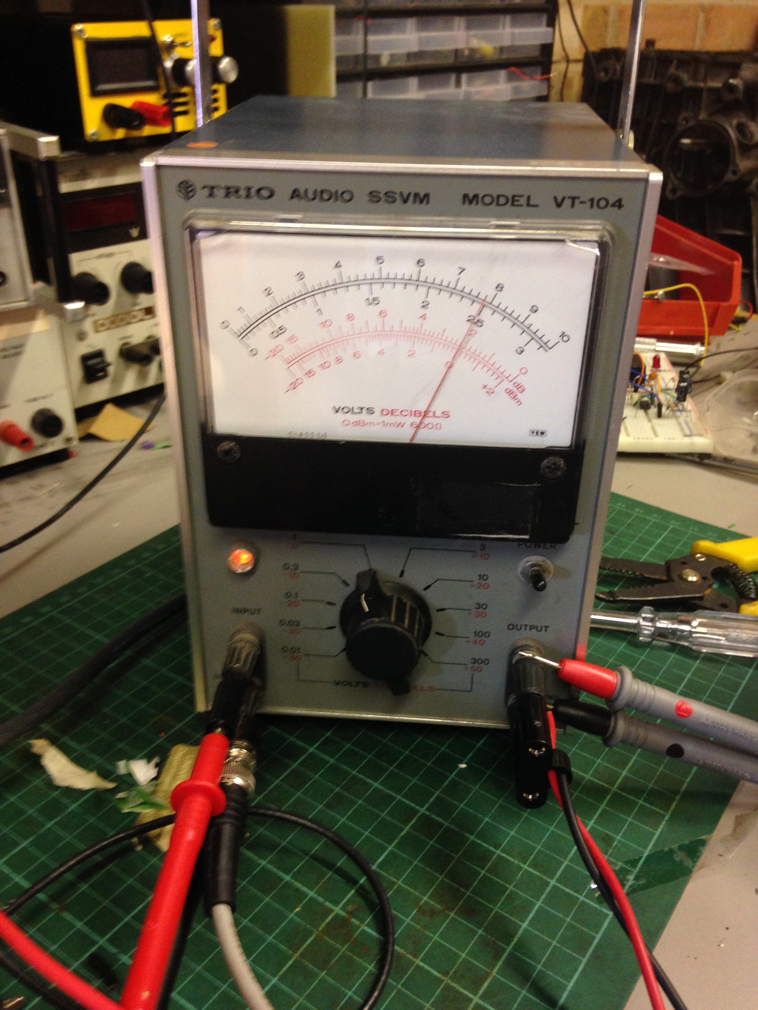
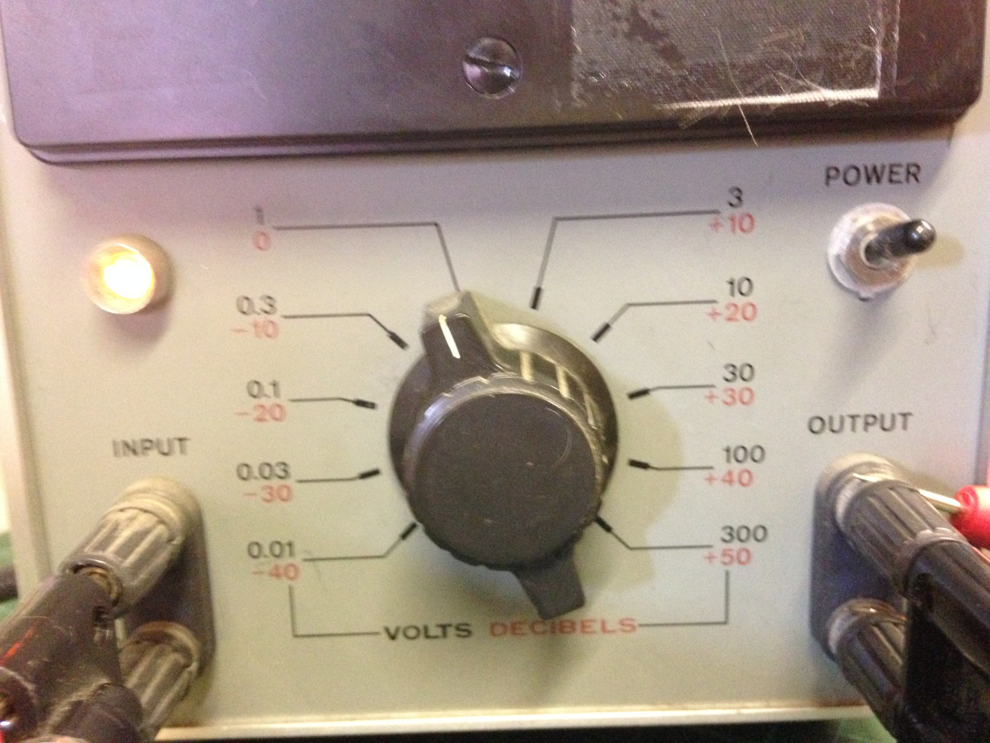
As can be seen: there's an input, an output, a range know and a power switch. The readings on the scale are Volts (dual range: 0-10V and 0-3V) and another scale in red has dB and dBm.
What is dBm
dBm is a measurment of power with respect to 1mW. Like with measuring gain in Decibels, except it is not with respect to the input power, but a specified value (1 milli-watt in this case), and is calculated as:
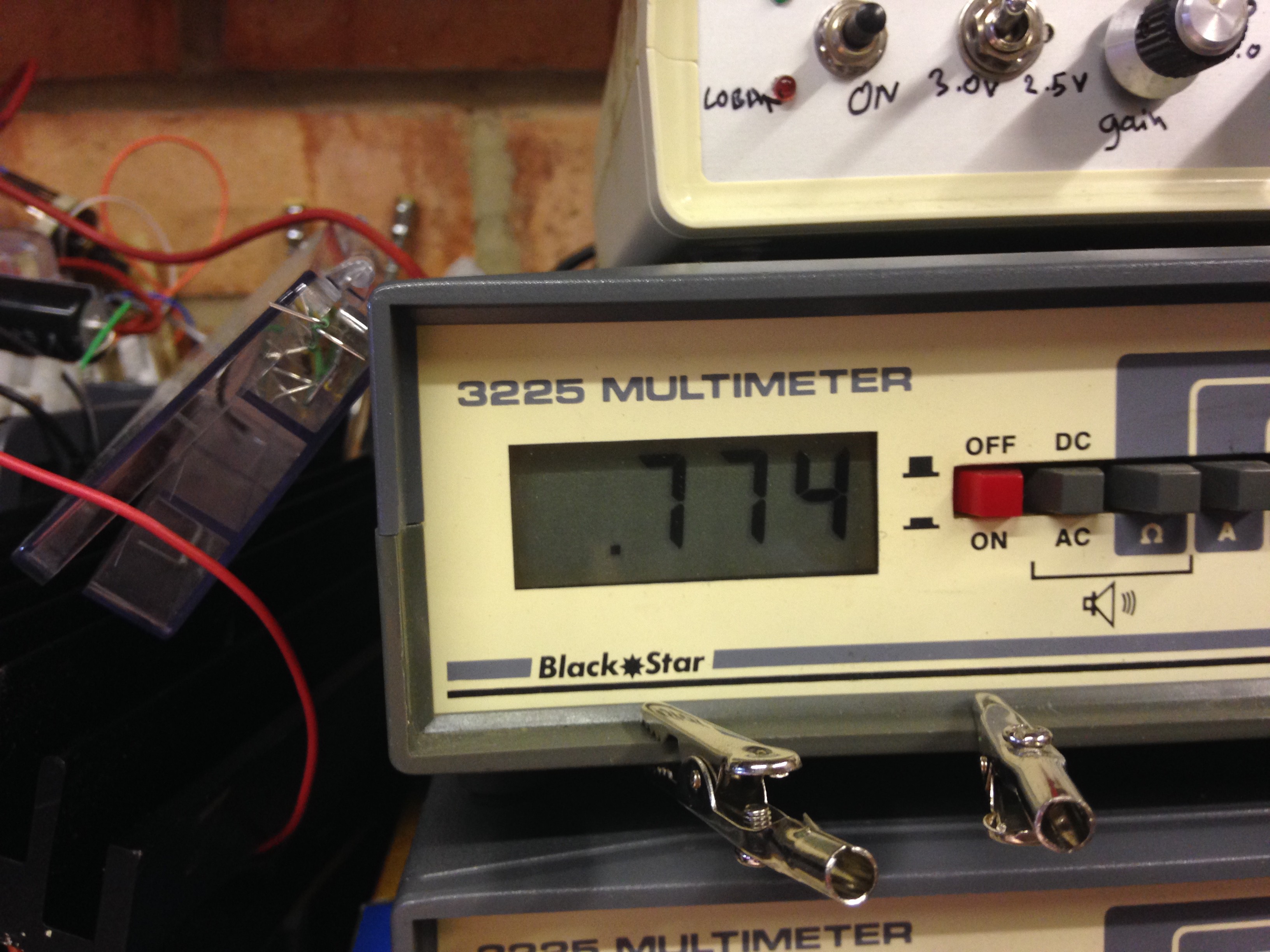
In Audio electronics, 0dBm is specified as 1mW into 600R. This means that the voltage into a 600R resistor would be 0.774Vrms, given that:
Now I know with a sinusoid, the above is not as simple as this, but for this demonstration, it shows the point simply.
With this in mind, we move on.
The Input
The main function of this meter is its a voltmeter whereby the range/scale is adjusted by the knob on the front:
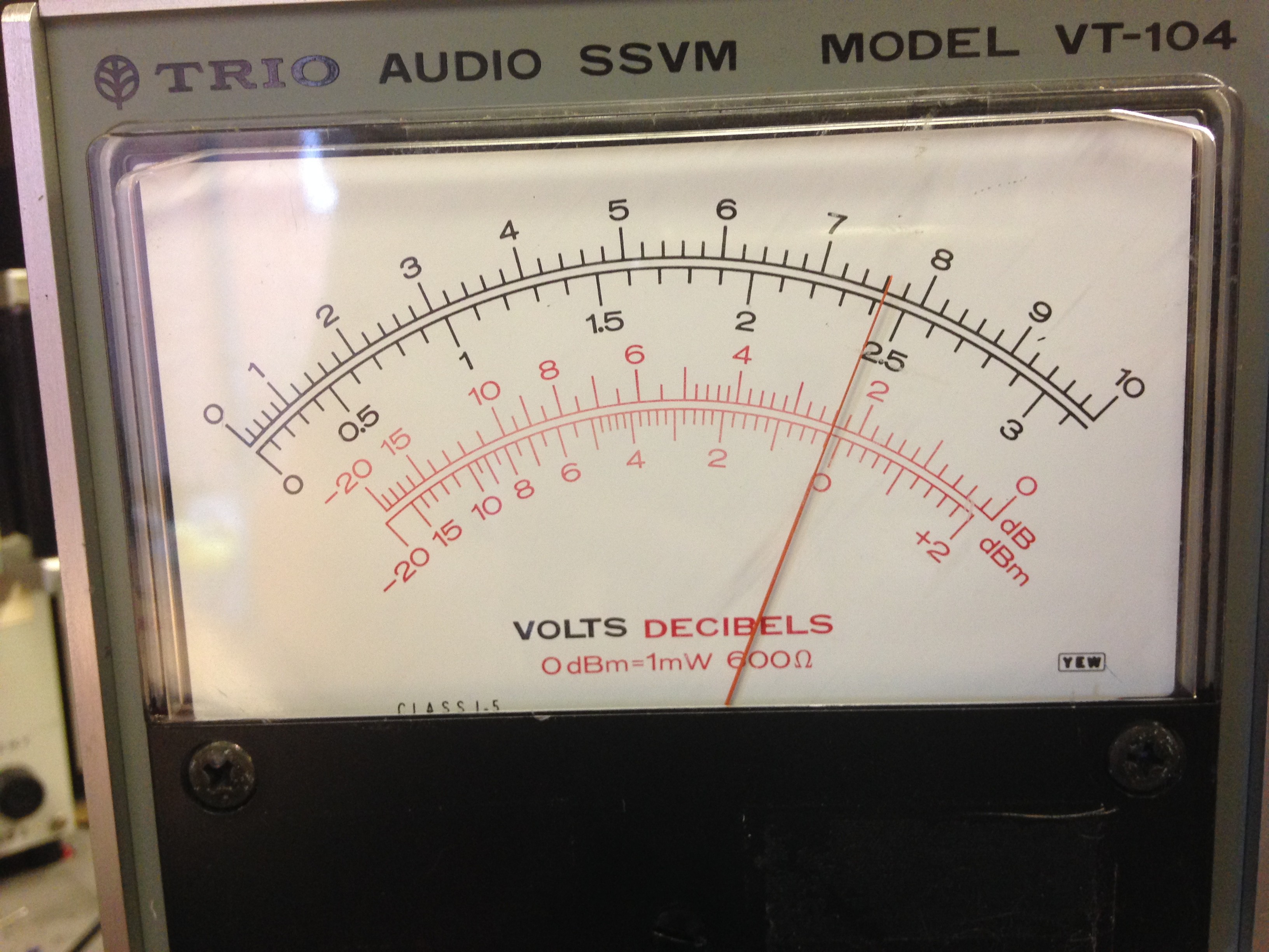
First I put the range know into the 1/0dBm scale. So with a 1kHz sine wave input from my sig gen, I adjusted the input till the meter read 0dBm and the pionter also reads off teh voltage on the same scale, which was 0.7-and-a-bit volts. This was confirmed by the bench DMM too.So basically the input is just a voltmeter with a cleverly placed scale for dBm and dB.
The Output
The output terminal is the clever bit. The output is dependent on 2 factors:
- The load connected to it
- Its scale selected
With the input still set to 0.774V, I connected a 600R (using a resistance box) load to the output and measured its voltage. The reading was exactly the same as the input.
I then reduced the load to 300R and measured the voltage, this time it was 0.524Vrms
Remembering that:
This meant the the power dissipated in the load was 950uW or near as damn it 1mW. If you fed that the equantion to work out the dBm you'd get 0dBm.
So even though the load changed, the meters output changed accordingly to deliver the same power into a different load.
Another thing that I noted was that the output voltage range never changes with respect to the scale selected.
Before I get onto this, I first would first like to state how you read this meter:
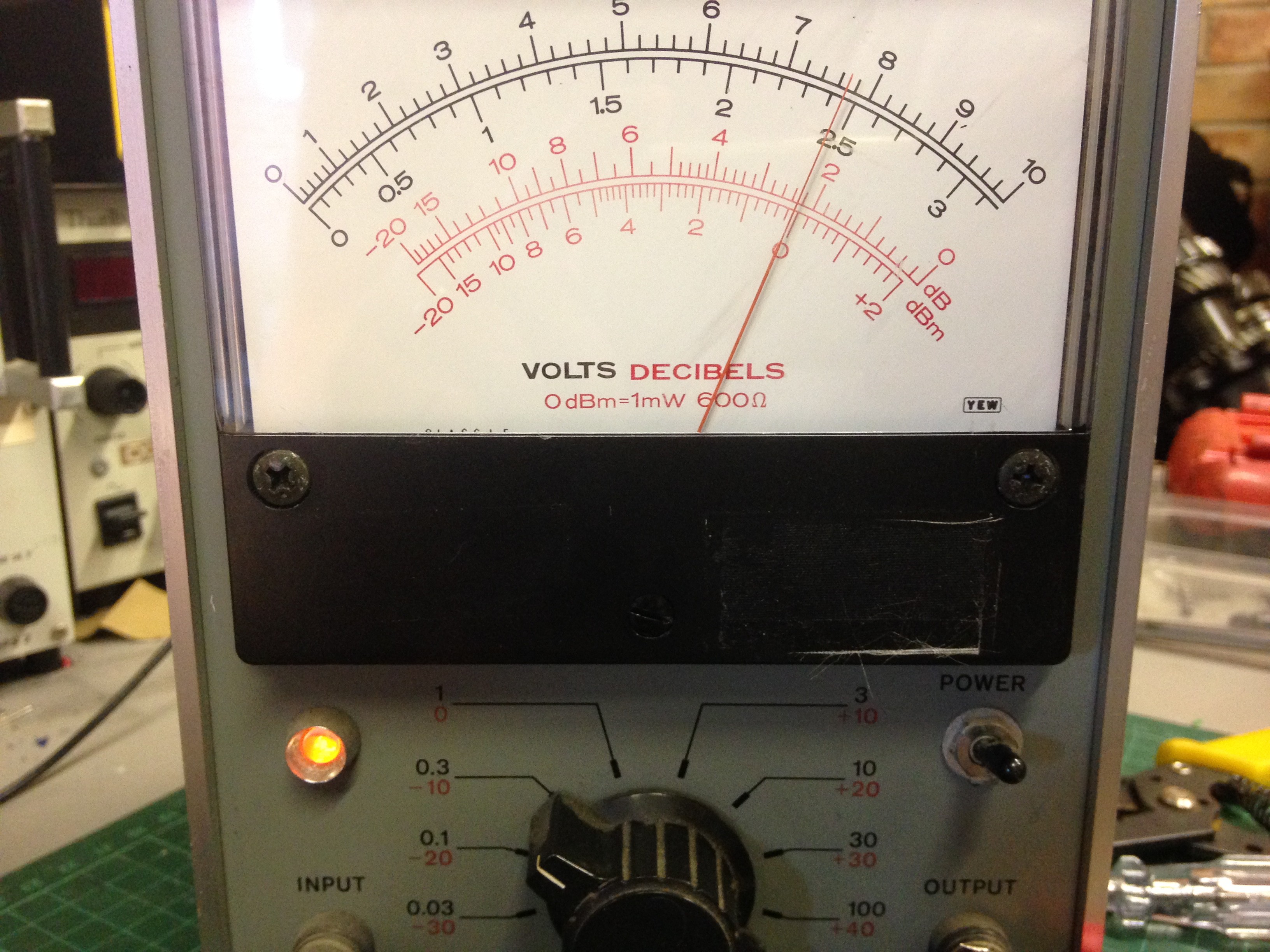
Reading the meter:
Above, the range is set to 0.3V fullscale and -10dBm. What this means is that on the dBm scale whatever the needle points to, you add the range selected.
So above you see that the -10dBm range is selected and the needle is pointed to 0dBm, this means that the value is: 0 +(-10) = -10dBm, and this is furthermore proven by the voltage input which was 0.248Vrms as read off the digital bench DMM I had hooked up. Thus:
Q.E.D.
Back to looking at the output
So with information on how to read the scale, I left the input at 0.248Vrms and the selected scale to -10dBm. However the output into the 600R load was 0.783V.
I multiplied the output voltage by the full scale voltage (0.3) to get 0.2349Vrms. using this value I worked out that even though it was still delivering 0dBm into a 600R load, if fact it was scaling it against the -10dBm scale.
So when the output voltage = 0.774Vrms into 600R load on any selected scale, its at the 0dBm mark.
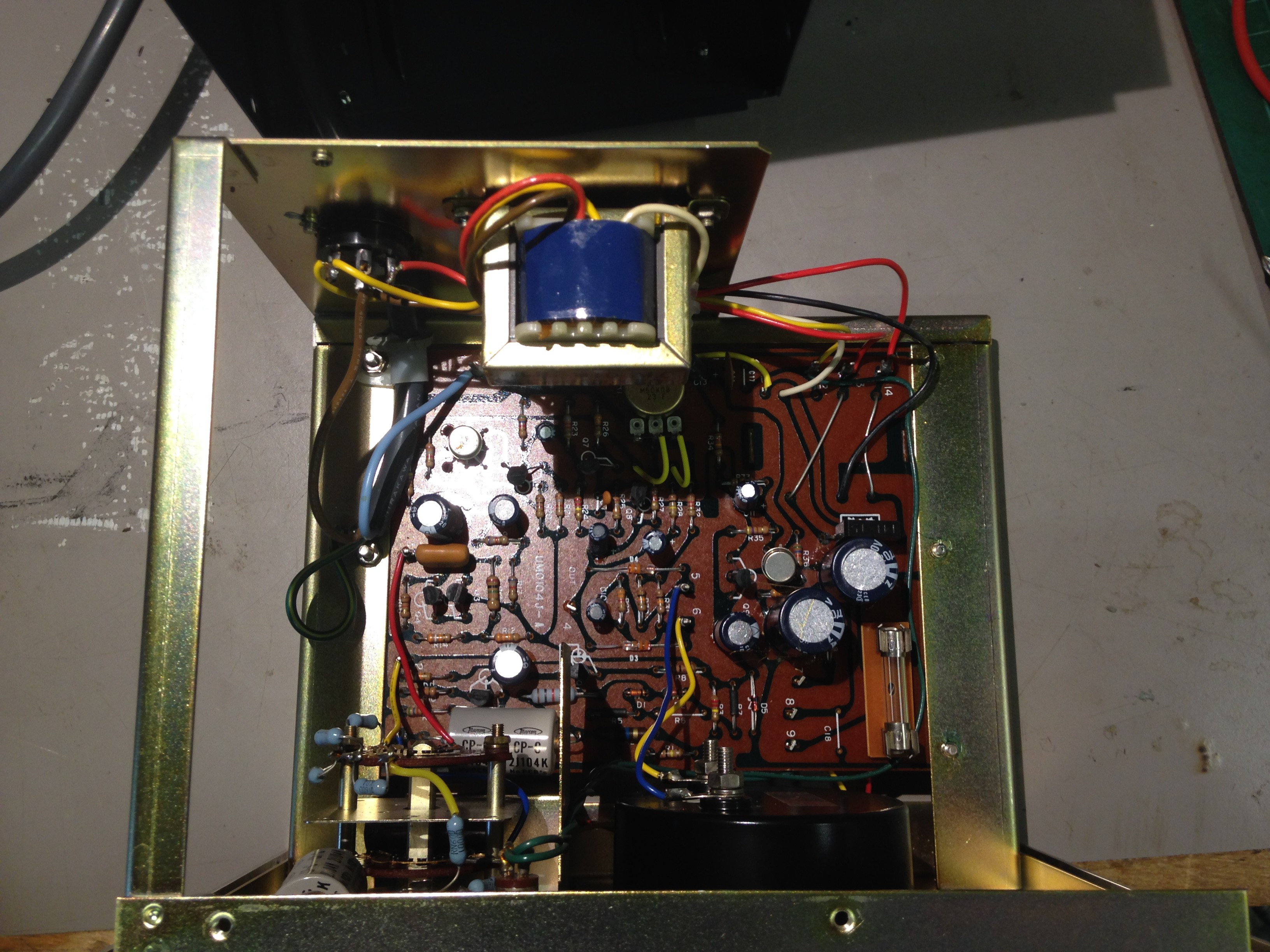
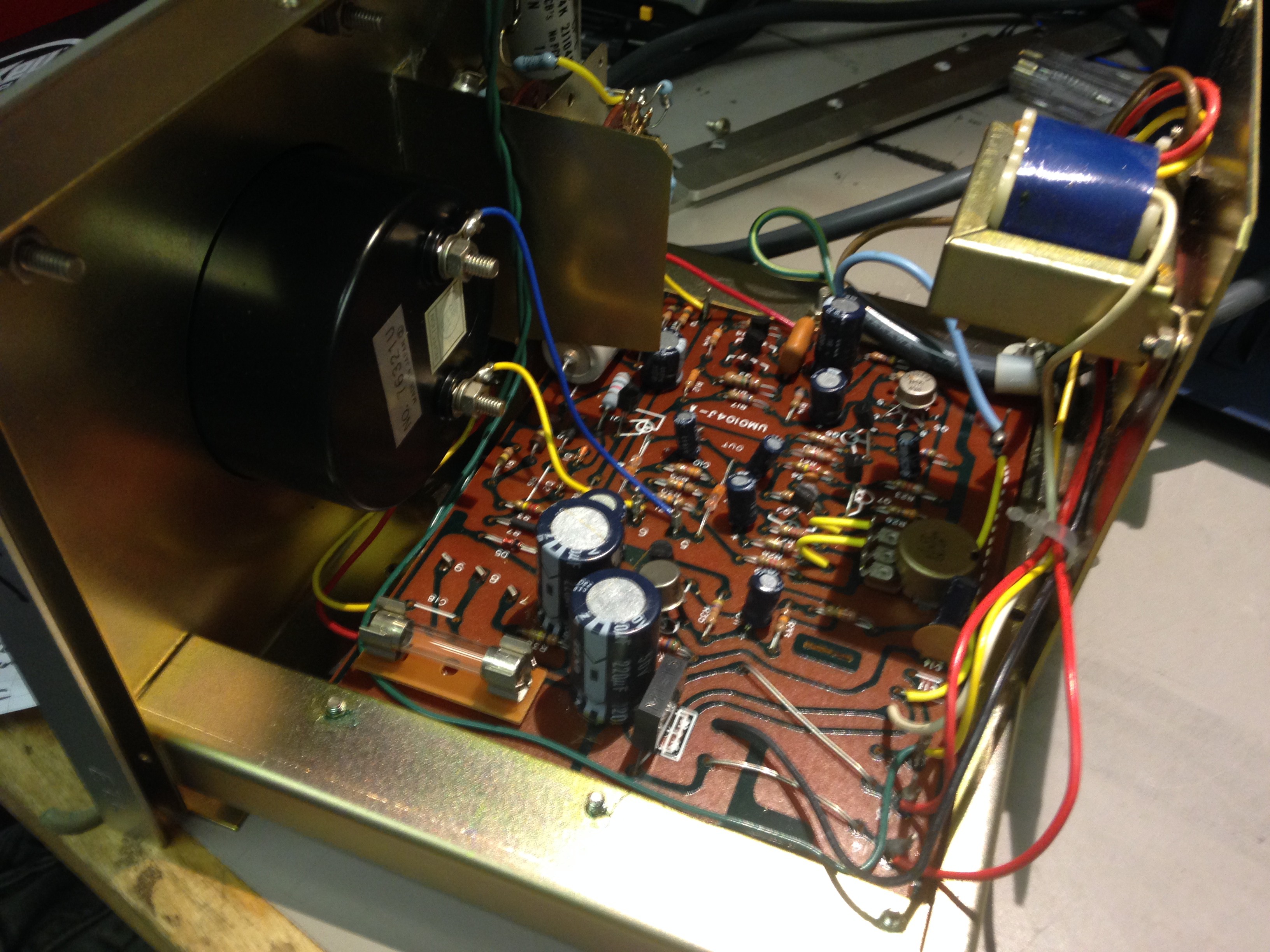
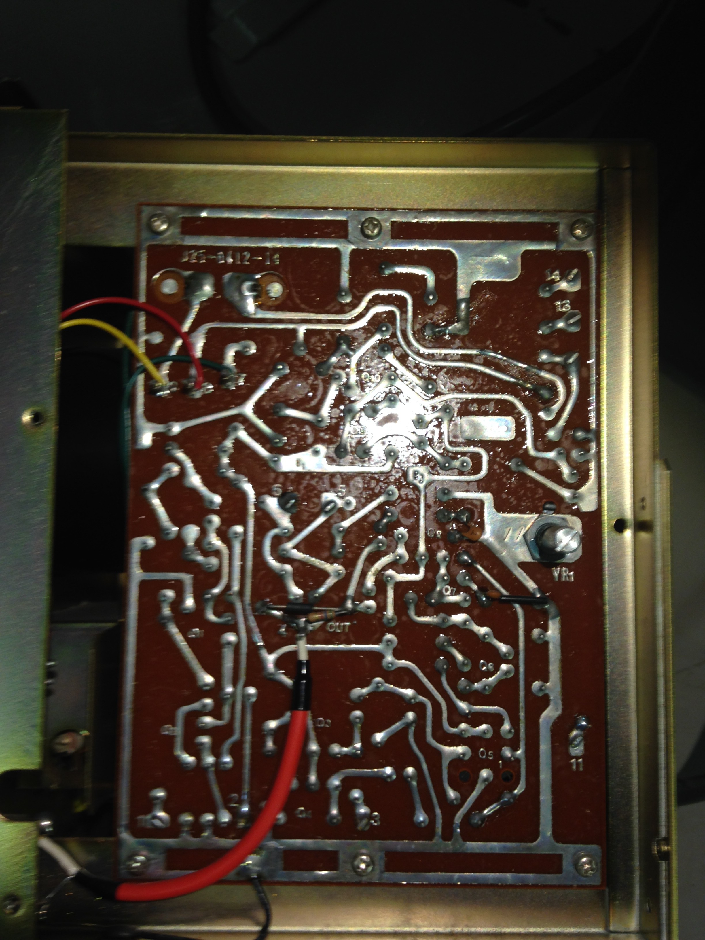
Shots of inside
Nice old school wire wrap!
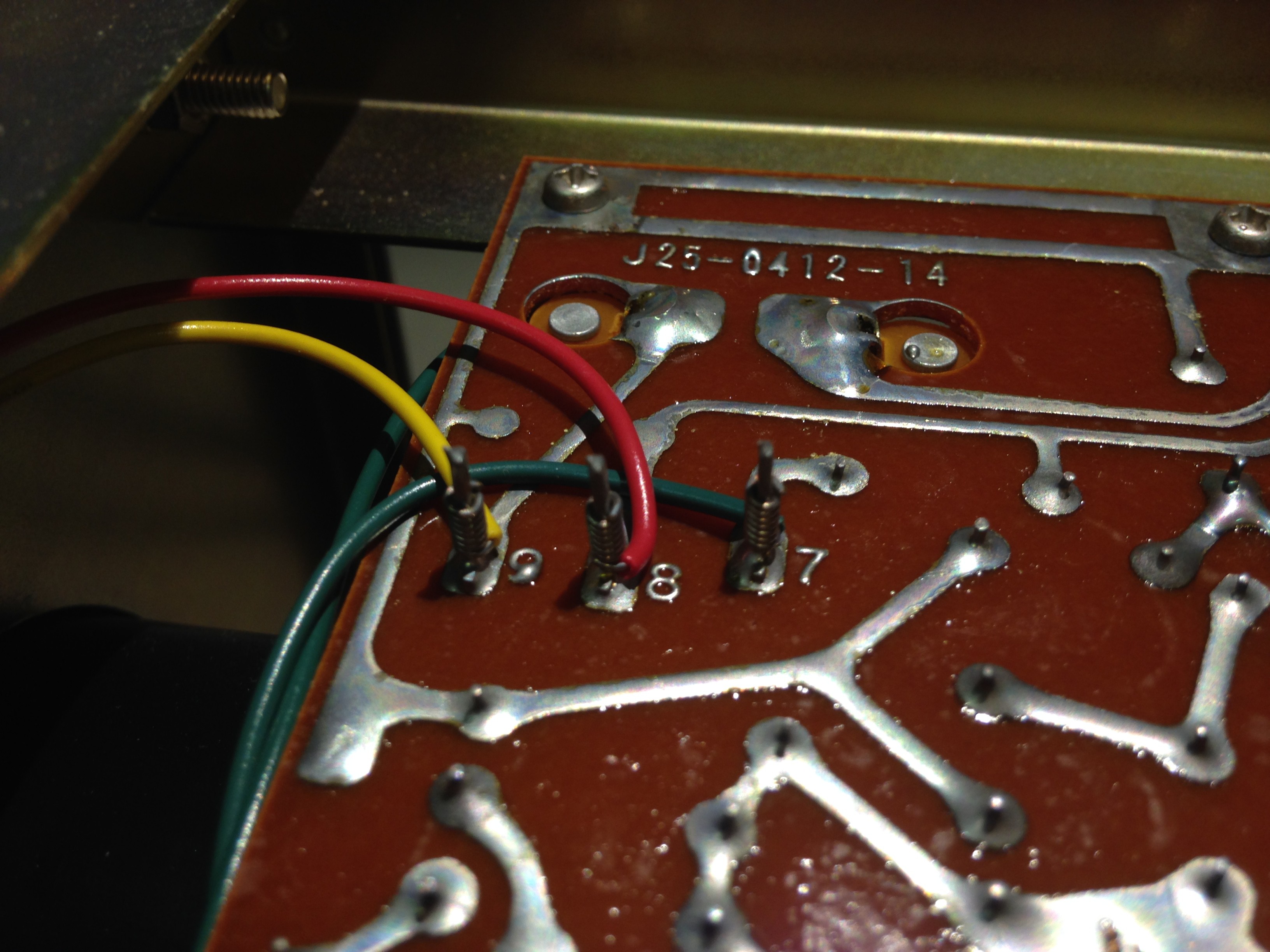
AHHH! The Chassis is connected to the GND of the output! Beware!


