-
Controlling Light with "Layers"
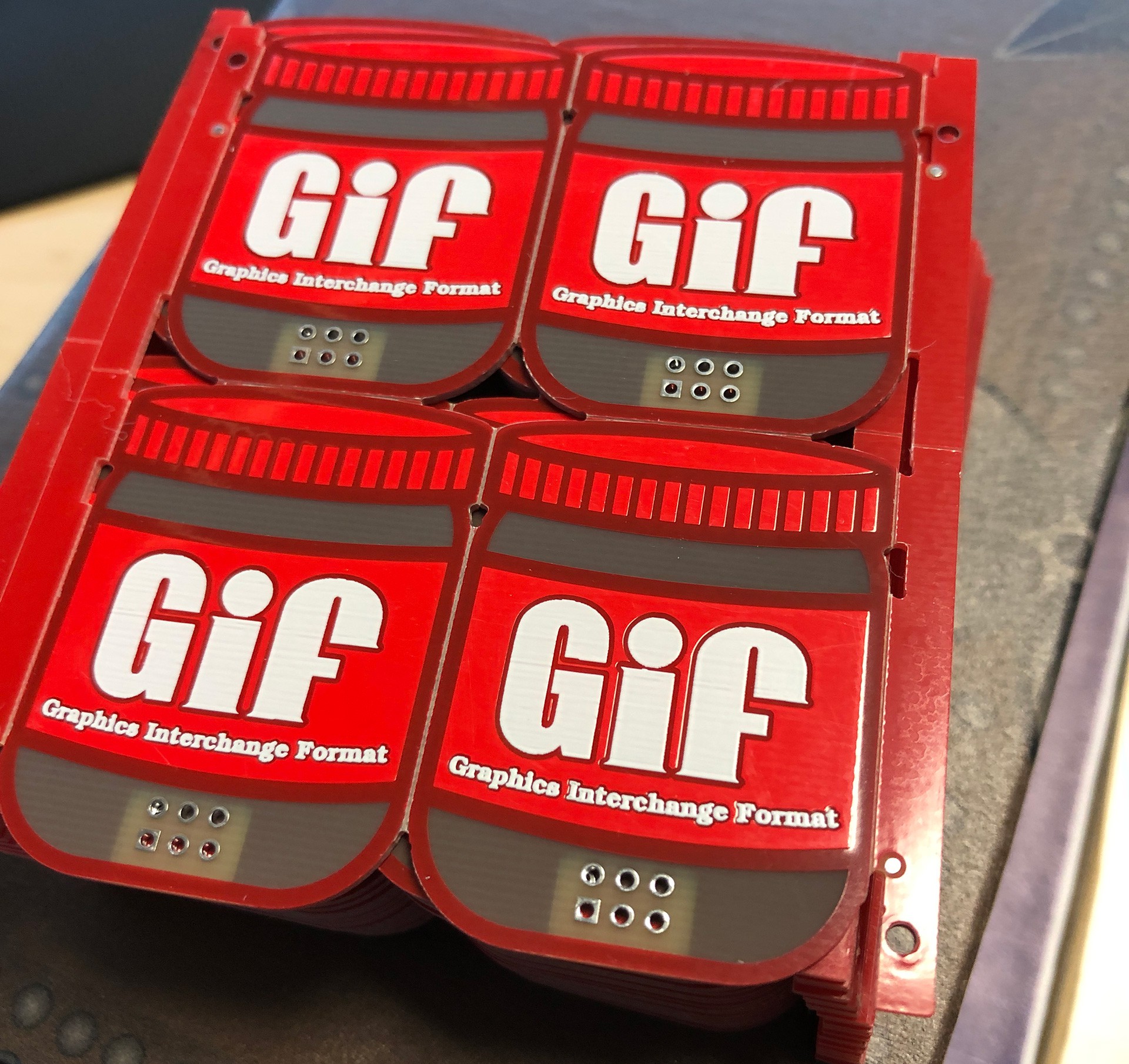
07/28/2020 at 12:39 • 0 commentsI have a friend, his name is Hyr0n, and he's been afflicted with the notion that "GIF" is pronounced" JIF, as in Peanut Butter. We all love Hyr0n so we forgive him for this deliberate misunderstanding but that doesn't keep him and I from ragging on each other at every opportunity so in that spirit I created the "Peanut Butter" SAO in 2019.

The idea behind this shit post of a shitty add-on was to simply present "Gif" in the same format as the beloved "Jif" peanut butter. However this quick last minute SAO turned into an exercise in controlling light bleed and there were some lessons learned that I'd like to share with everyone.
In early 2020 Giphy and Jif actually teamed up and released a special "Gif" peanut butter jar. It was $10 at release but is now, as of July 2020 about $34. 2 Layers is not Enough
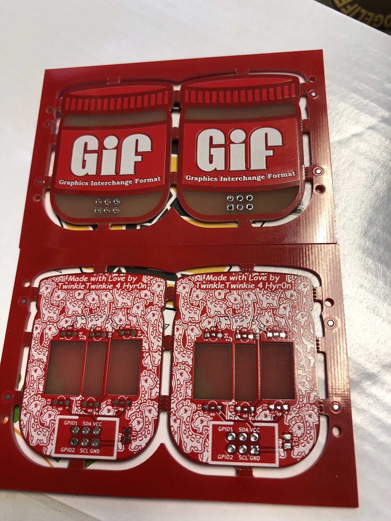
The original design for "Peanut Butter" was incredibly simple. Featuring a mock up of "Gif" in the same spirit of a jar of "Jif" I spent most of my time making a G out of a J and then filling the back with a bunch of Giraffes so as to split the difference on the two arguments, and thus making both sides think they were right. I quickly threw together a schematic that featured 6 white LEDs that would back light "Gif" and sent it off to fab with the extra bit being I had it panelized to see what that would look like and here is the result:

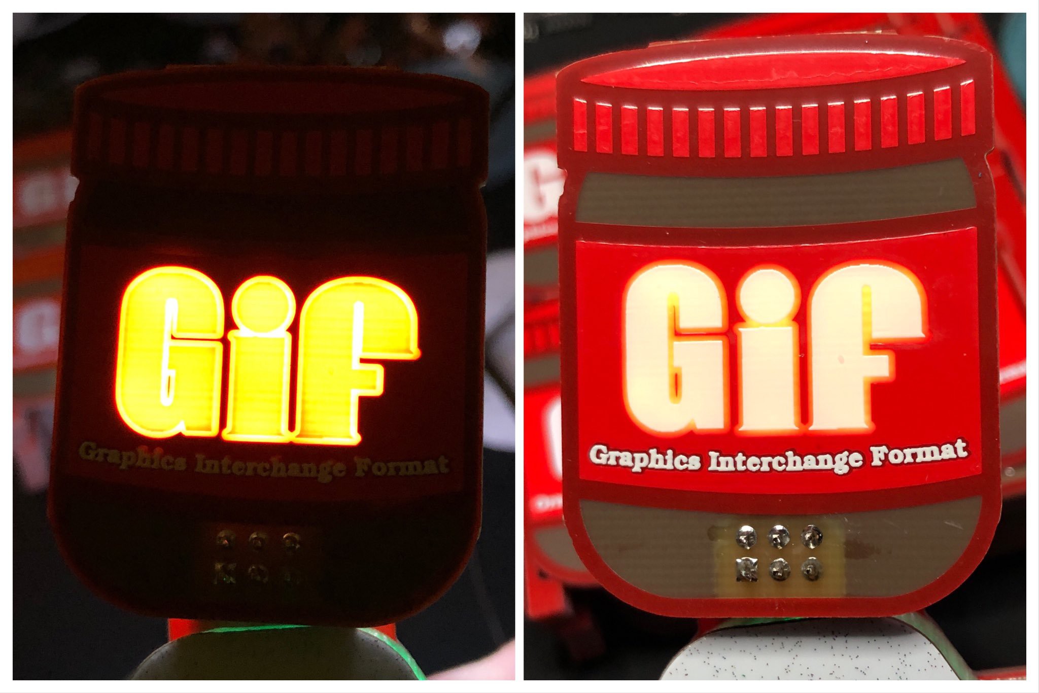
The results were great! Except that is until I put on the LEDs and gave them power.
The light bleed on this was really bad, I only wanted to light up the words and despite using side mounted LEDs that were only pointing inwards on the letters the light was so bright that it covered way more than intended. So I chewed on this for a couple of days and then it occurred to me that maybe I could add more layers between the top and bottom and control where the light was visible without affecting the top copper art.
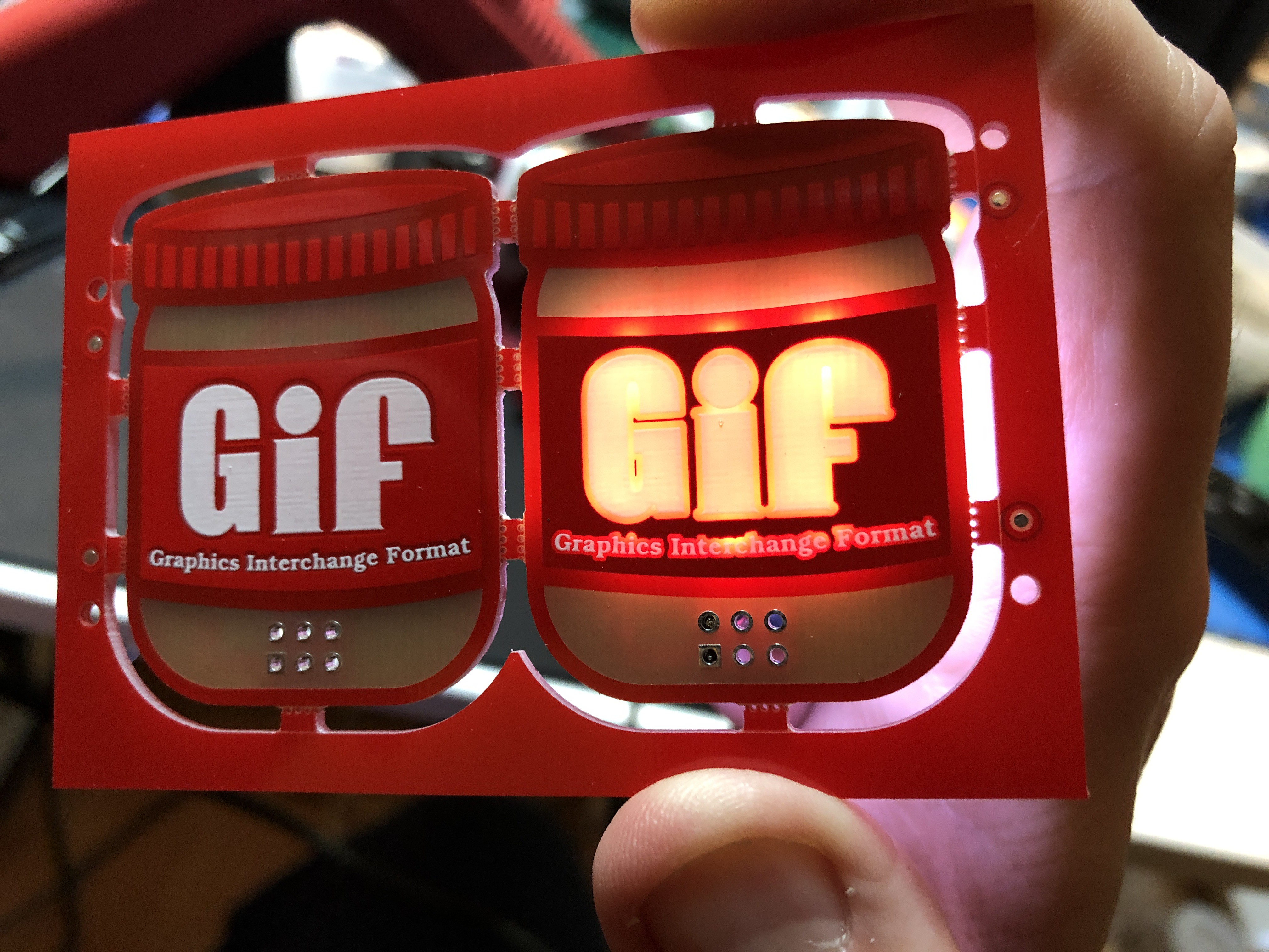
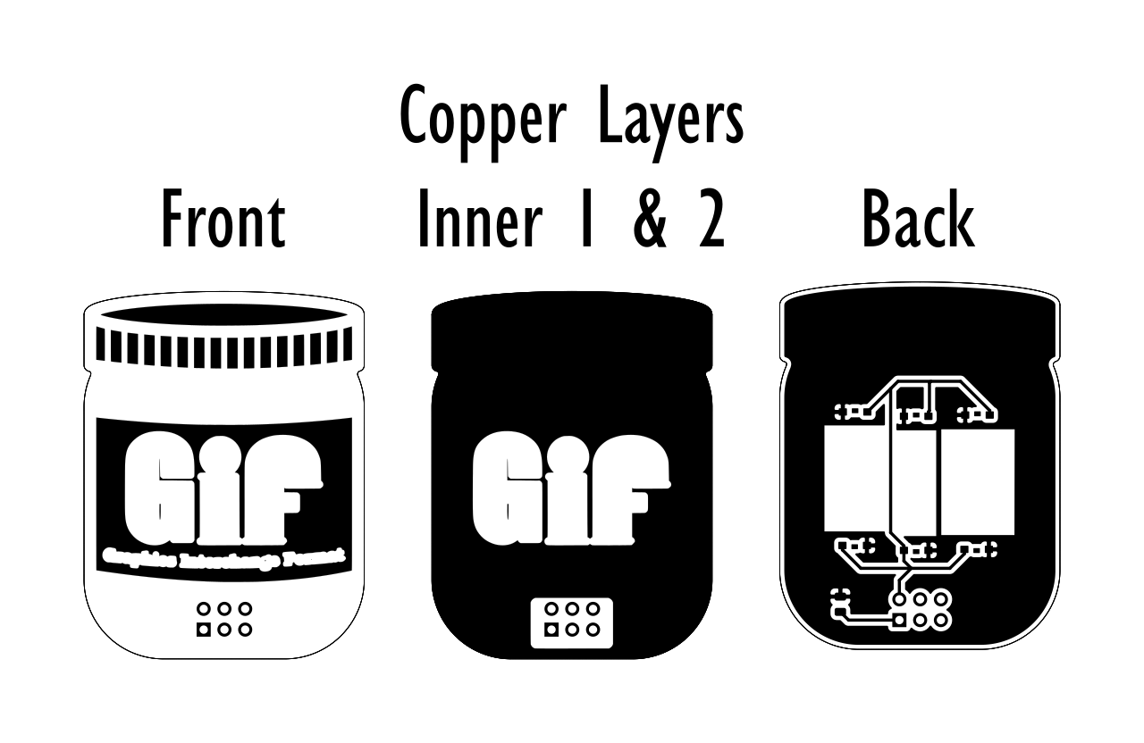
The second revision of Peanut butter had 4 layers with "Gif" being the only open areas in the copper on the two inner layers. I probably could have done this with only one layer of copper but I wanted to be sure it'd block as much light as possible and you can't order a 3 layer board anyway.

This change worked perfectly and due to a misunderstanding on my part when ordering these instead of ordering 25 boards I ordered 25 panels so I had a lot more to give away.
Controlling light bleed? You need more "Layers"! If you're designing a board where light will be intentionally shone through the back and if you're looking to control exactly where that light is shown without affecting the top copper layer then you'll need to use inner copper layers to get the results you're looking for.
In general this realization made other projects easier as well. When you only consider using two copper layers then suddenly the back copper layer becomes a consideration for the art you're trying to display on the front. If you don't want visible trace lines or are trying to control the way light is presented then you can utilize multiple layers to achieve your end goal. You might be wondering how much more this might cost you and that varies from fab to fab but from JLCPCB the cost of moving to 4 layers from 2 isn't that much more and if you panelize your designs you can get a lot more individual boards for your money. -
Santa Bot PCB Made by PCBWay
12/17/2019 at 17:22 • 0 commentsFor the last 4 years I have created a Christmas Ornament to help raise money for Charity. The first ornament was created for a Secret Santa event for a Computer Hardware forum called "[H]ardForum". It is the forum attached to the now defunct hardocp.com. The "General Mayhem" portion of that forum was composed of a tight knit group of people who gave each other endless hell but at the end of the day looked out for each other and really did try to help out others when they needed it.
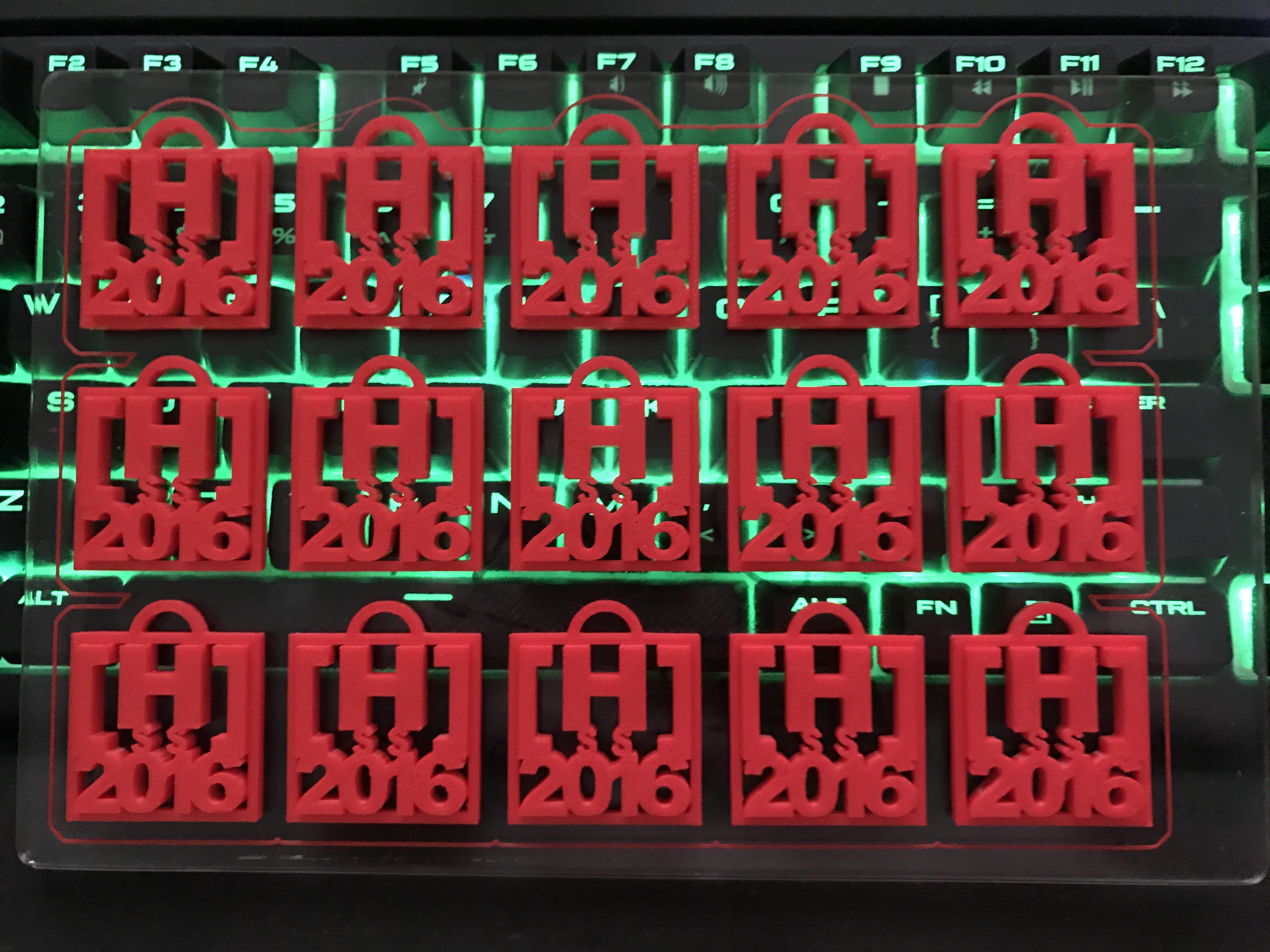
The Secret Santa event was started in 2005 and was run by a handful of people before I took over the in 2016. When I took over I discovered that a number of people who had participated in the event in prior year weren't returning because of recent hardships. Some were dealing with overwhelming medical bills, some were recovering from losing their jobs or were currently in between jobs because of a large lay off. That's when I decided to make and sell 3D Printed ornaments. The ornaments raised money so we could buy gifts for those who had fallen on "[H]ard Times" and any left over money would be donated to "Child's Play Charity", which was a favorite charity among the community.

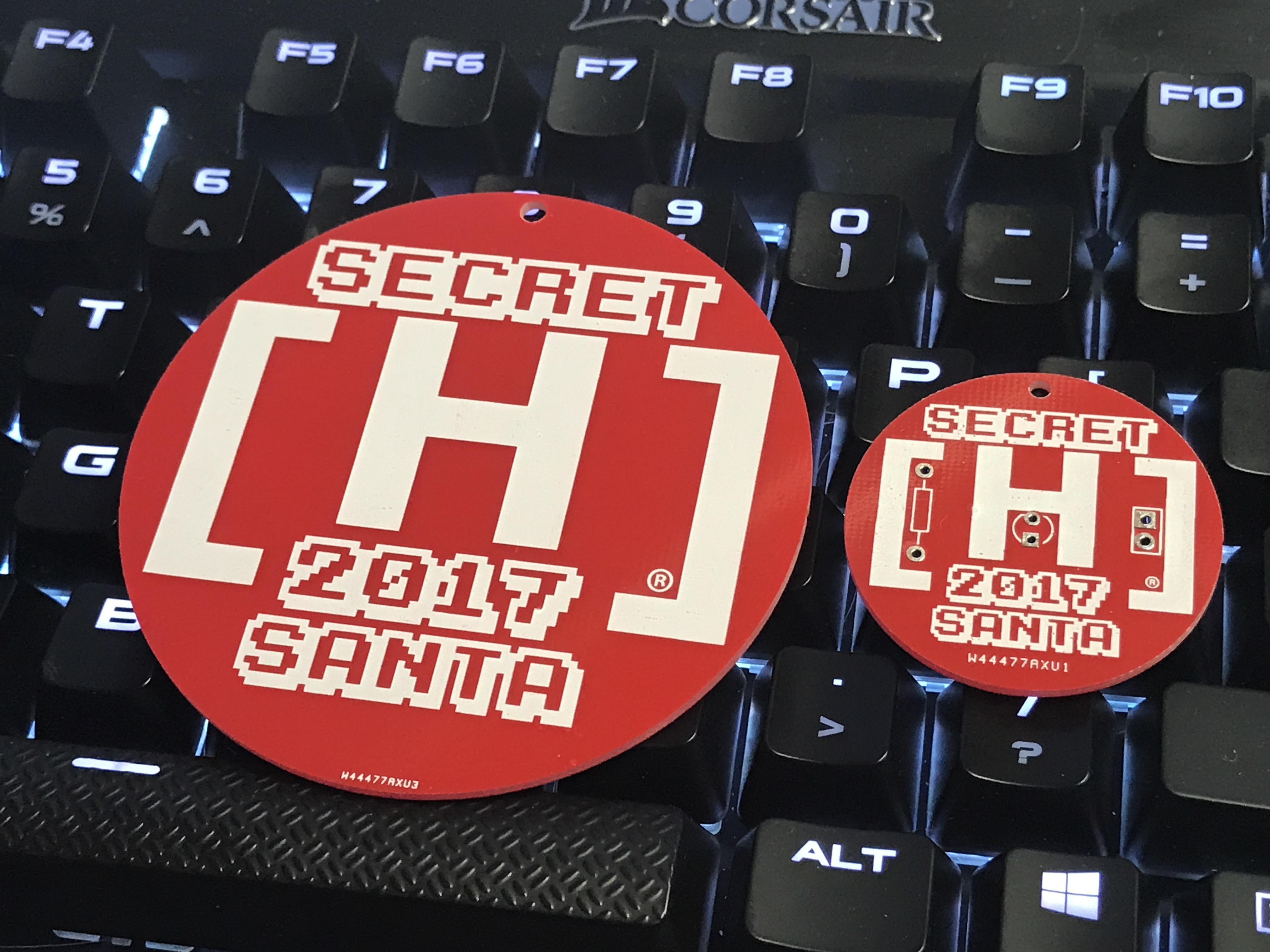
2016's Ornament was 3D Printed I continued the Ornament in 2017 but that year rather than 3D Printing the ornaments I decided to put my newly acquired Fritzing "Skills" to use and had PCBWay produce a Token and a Ornament. Just as with the 2016 ornament the 2017 Ornament & Token were used to raise money to buy gifts for those experiencing [H]ard Times and again the remaining money was donated to the Child Play Charity. While we reached our goals for the ornament in 2016 in 2017 they fell short. We were still able to raise the minimum amount we needed to cover costs and to buy gifts but we didn't sell as many as we had hoped and thus weren't able to donate as much to Child's Play Charity as much as we would have liked. We felt the biggest issue was that the ornament was catered to a really small group of people and that if it were more generic and offered to the general public we may be able to do more with it.

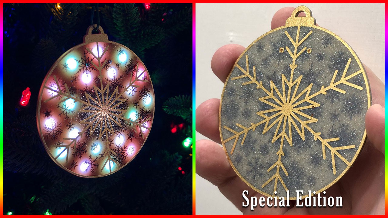
2017's Ornament was my first and second PCB Designs which were created in Fritzing In 2018 I spun my Holiday Ornament off from [H]ardForum and rather than it being used for both [H]ard Timers & Child's Play Charity the money was raised solely for Child's Play Charity and the ornament became available to more than the [H]ardForum community. At that point I was neck deep in #badgelife and had a great deal more experience making artistic PCBs. My 2018 Ornament was a big success and sold out in 3 days and raised $1,000 for Child's Play Charity (https://twitter.com/mrtwinkletwink/status/1069051869710991360.

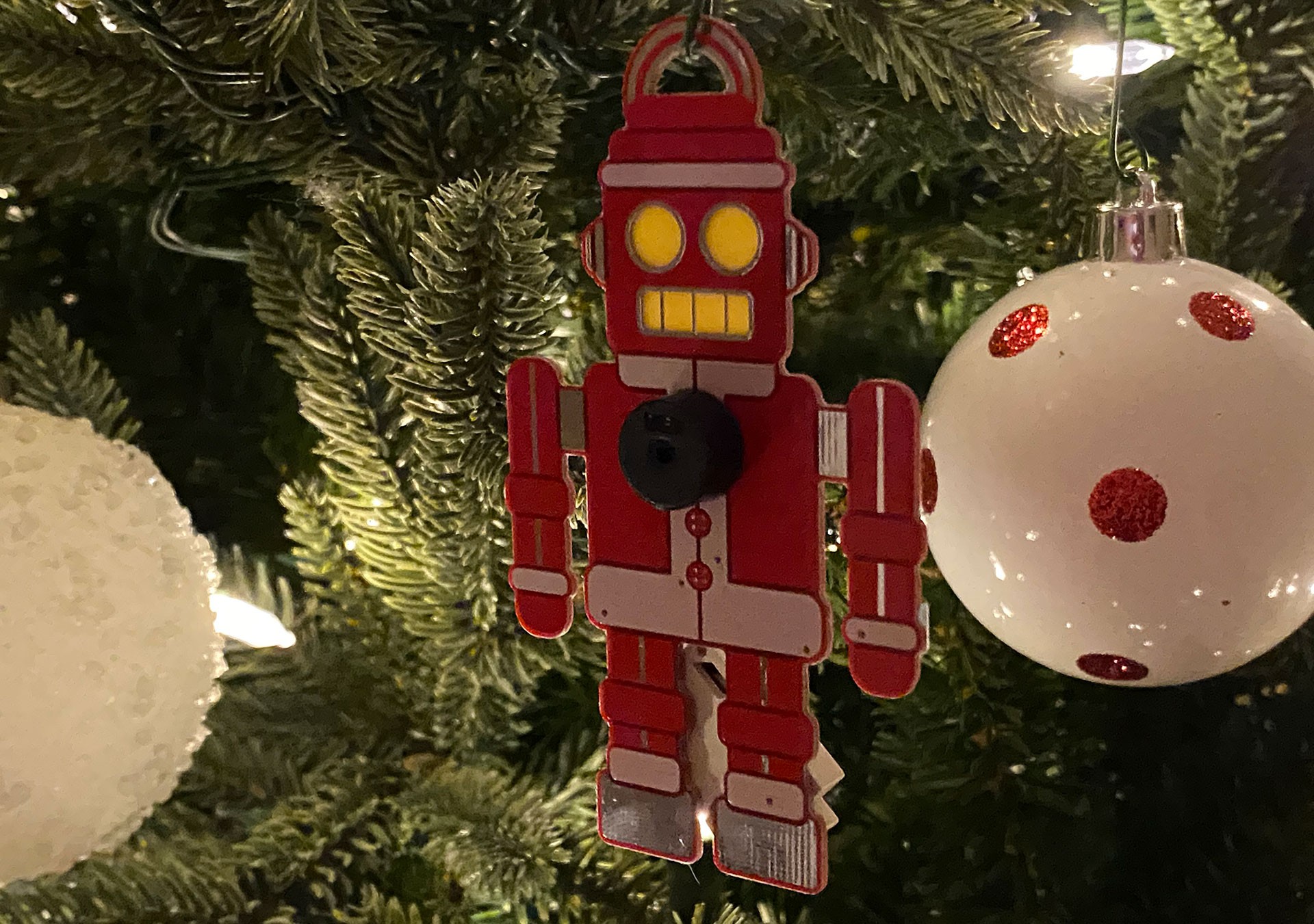
2018's Ornament, this was my first 4 layer board designed in KiCad This brings us to the current year, 2019, and this year's Ornament is "Santa Bot"! Santa Bot is the evolution of my collaboration with @Nick on "Wireshark" and instead of playing one song it plays 11 and features glowing eyes and a blinking mouth when "singing". Santa Bot was inspired by vintage robot toys from the 1960s whose characteristics are brought to life with a Red Solder Mask, White Silk Screen, and a HASL (Silver) Copper Finish on a board produced by PCBWay.
2019's Ornament: Santa Bot - PCB Made by PCBWay PCBWay sponsored this year's board so that more of the money raised can go towards the Child's Play Charity. PCBWay has manufactured the majority of the boards I've used on my projects including Arc Badge, Krusty the It, Mad Cat, and Chestoro!
Placing an order on their website is easy and straight forward. You enter parameters about your board, choose your Silk Screen, Solder Mask, Copper Finish, and if you need it they can produce a stencil for you to use with Solder Paste as well.
Their ordering process is setup so that they review...
Read more -
2019, A Year in Tools
12/12/2019 at 14:49 • 0 commentsToday I was talking with a friend about some difficulties we had with assembly with a particular part and I shared with him the tool I purchased to deal with the problem. While going down my purchase history looking for the tool to share with my friend I realized that I actually bought quite a few tools in 2019 and I thought it'd be fun to share with you the tools I purchased and used this year. These tools will be in order of when I purchased them. The order of purchases tells its own story.
While I will provide a link to all of the tools I purchased, none of the links are affiliate links so don't feel obligated to use them if you decide to make your own purchase.
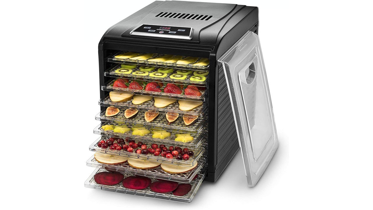
Gourmia GFD1950 Digital Food Dehydrator
Amazon: https://www.amazon.com/gp/product/B01M6AZ863/

I purchased this food dehydrator to dehydrate the least food related thing I consume on a regular basis: 3D Printing Filament. I had been having printing issues with a couple of rolls of filament and I had calibrated and recalibrated my printer numerous times. I live in a humid state (my house generally sits at about 50% humidity) so despite my efforts to keep my filament dry I figured I'd try out drying it with a Dehydrator. I haven't gotten too far into the weeds as far as dialing in specific settings or timing I just leave it at the default 165F for 10 hours and I toss it in the dehydrator, run the cycle and use the spool the next day. Even though filament is pretty cheap it can take me a while to actually use an entire spool so this Dehydrator has already more than paid for itself and I've worked it into my regular work flow with my 3D Printer, especially for spools that have been sitting in storage for a long time.
Depending on the size of the spool I can generally fit 3-4 1KG rolls of filament in this dehydrator. I normally use it on my PLA rolls but I have also used it on PETG rolls and have noticed a significant improvement in print quality.
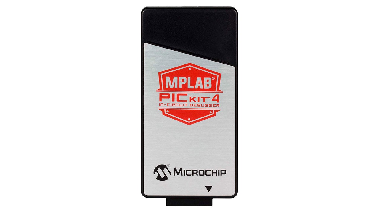
MPLAB PICkit 4 in-Circuit Debugger
Amazon Link: https://www.amazon.com/gp/product/B07DMSDGQX/

If you've done anything with a PIC then you might already be familiar with this tool. It's used to program PIC MCUs. Hypothetically it can be used to program more than the PIC Line of MCUs that Microchip makes but my own experience with attempting to program a ATTiny13a with it went poorly but I'm not the best person to judge this sort of thing. I used it to program the Arc Badge and it worked reliably the entire time. As long as you use it to program chips it has 100% compatibility with then you'll have a good time. Hypothetically you could put a MicroSD Card in this and use it to program chips without a computer but I wasn't able to test that out myself and while the hardware was there for it I don't think it was supported when I was doing it. Still, I think it was worth the purchase and again for the PIC MCUs I used it worked flawlessly.
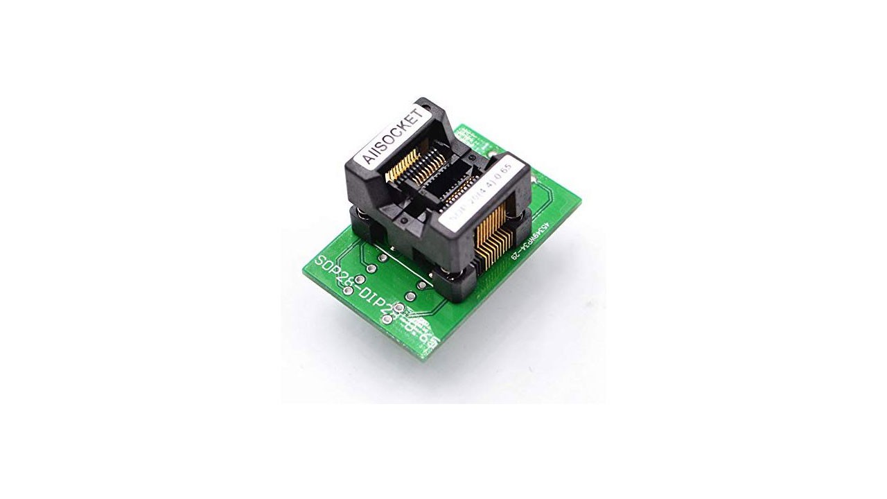
ALLSOCKET TSSOP20 Programming Adapter
Amazon Link: https://www.amazon.com/gp/product/B06XDNTGPD/

I only used this adapter a couple of times but it was useful when doing breadboard experiments with the PIC16 we used on the Arc Badge. I think if you like to bread board your designs first this is a good device to have if you don't have any break out boards or bread board friendly packages of your chip. As for this particular device I didn't have any trouble using it but again I only used it a couple of times and I haven't used it since.
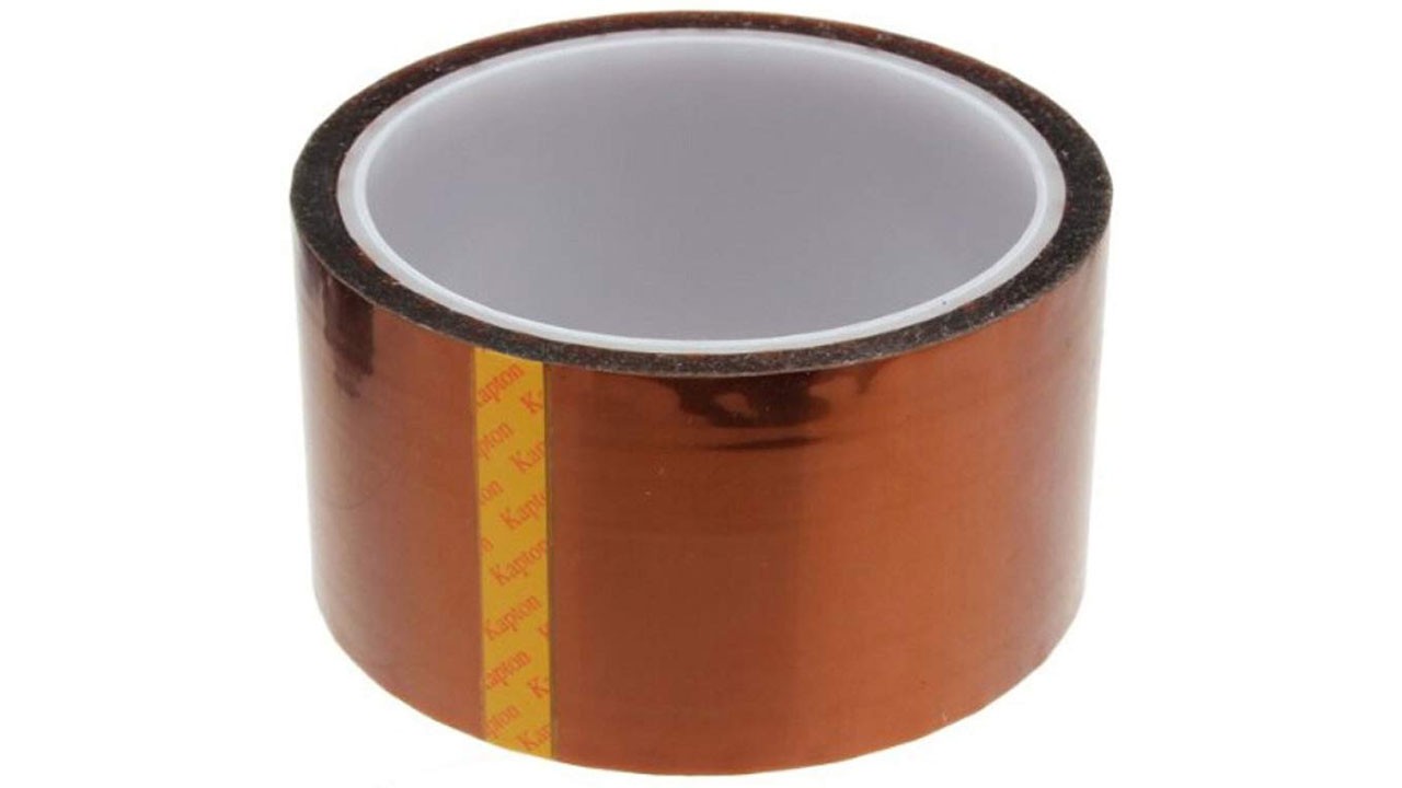
Kapton Tape (50mm*33m)
Amazon Link: https://www.amazon.com/gp/product/B00N1QZY4M/

I purchased this large roll of Kapton tape to do some modifications to a T961 Reflow Oven. It has worked very well and I've found myself using it a couple of other places around the house. Its tolerance of high temperatures and being that it's non-conductive it can have a number of electronic hobby uses. ...
Read more -
PCB Art with OSHPark After Dark
09/26/2019 at 15:59 • 2 commentsDisclaimer: The OSHPark boards pictured were designed by me (TwinkleTwinkie) but were paid for by OSH Park.
OSHPark recently announced their new "After Dark" finish option for their PCB Prototyping service which brings a wonderful new alternative to their traditional Purple Solder Mask & ENIG Copper Finish. "After Dark" brings two major changes to what you normally see from an OSH Park board: Black FR4 and a Clear Solder Mask.
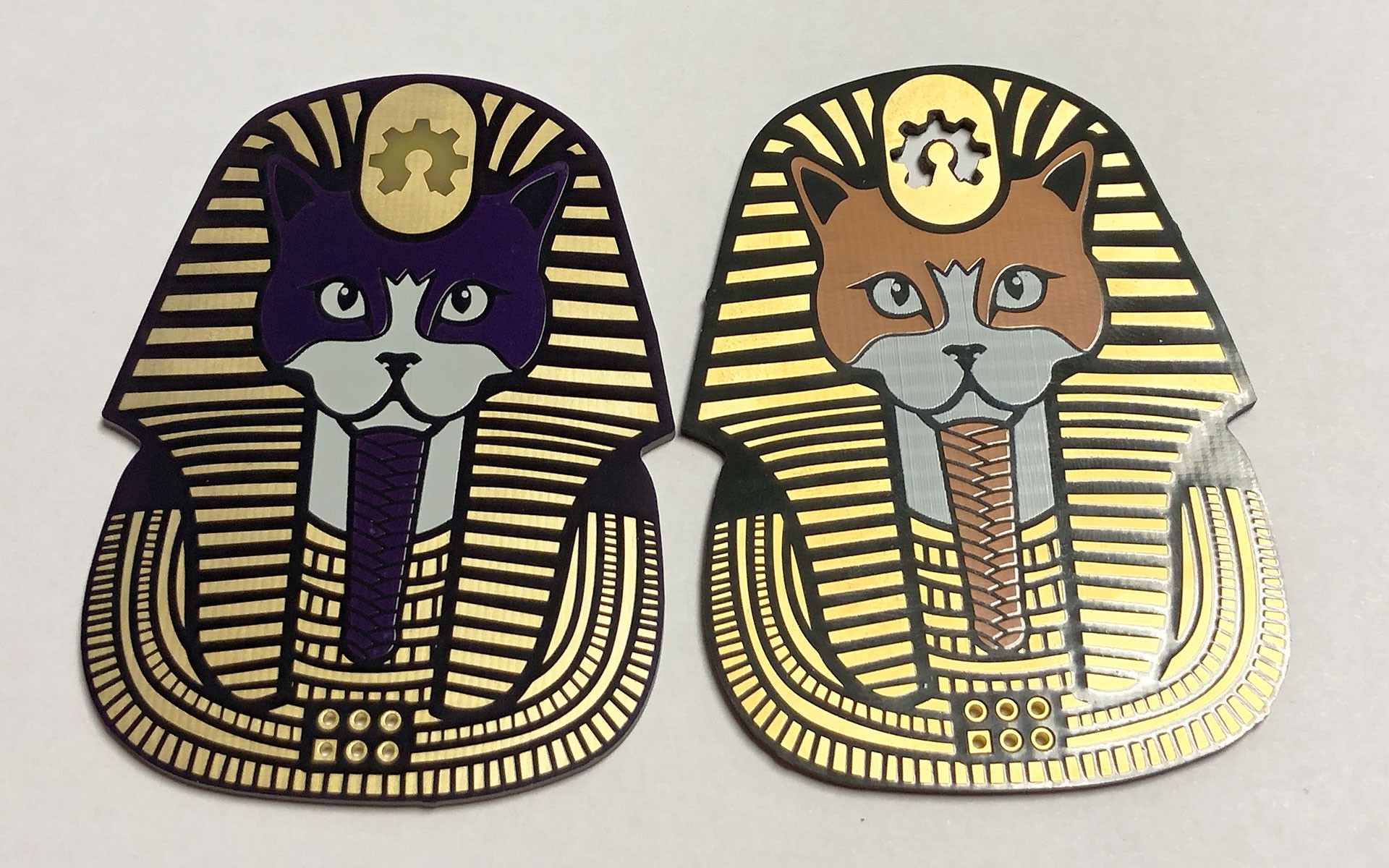
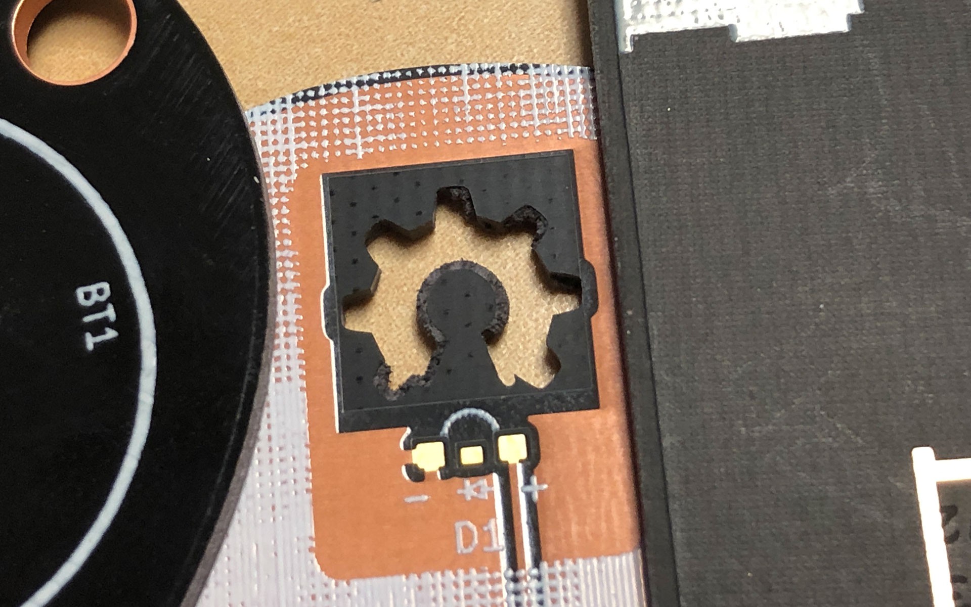
Left: Purple Mask & FR4 TG180, Right: Clear Mask & Black FR4, other than the finish and cutting out the gear symbol the design files were identical. Black FR4 is one of my personal holy grails for creating PCB Art. Although it isn't exactly unobtainium it is typically expensive and only a handful of Fabs have it as an option so as a result is rarely seen, even in #BadgeLife. The only example of it I am aware of is Queercon 13's Blooper Badge.

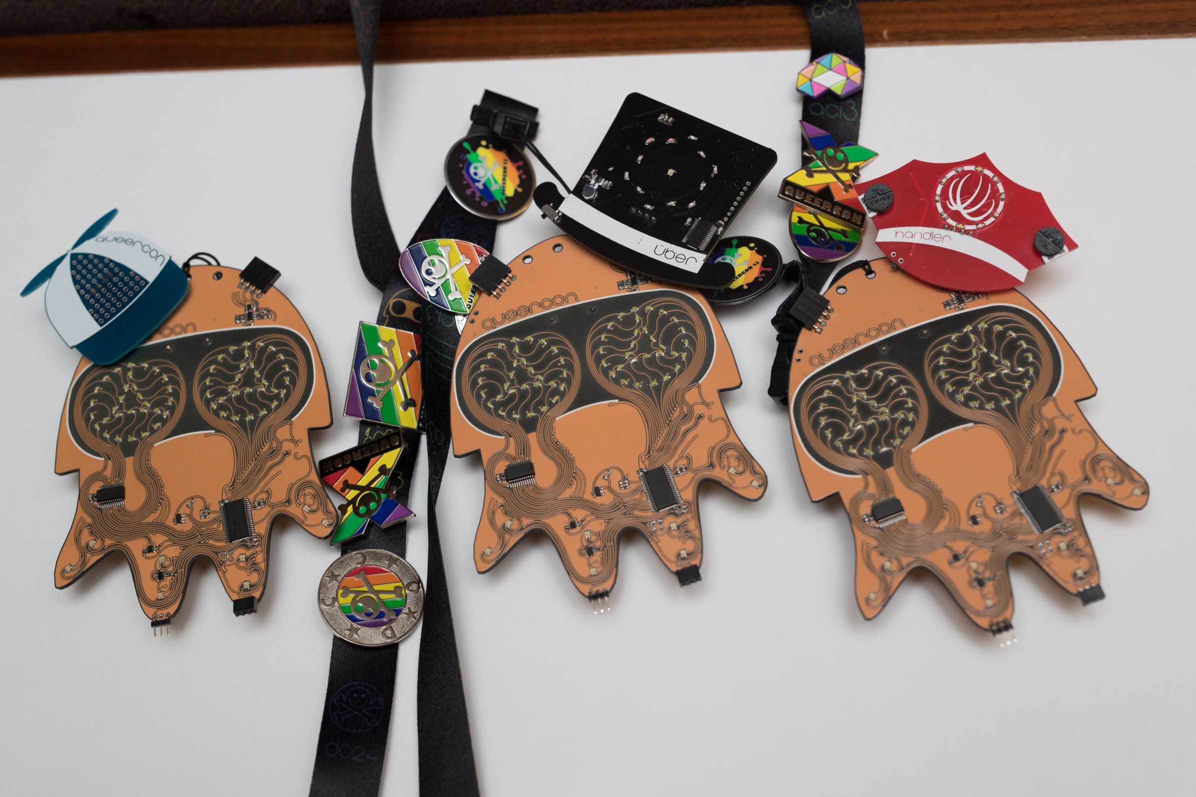
QC13's "Blooper" Badge with its various "Hats", the predecessor to the SAO - Photo by Eric Quaintance, Badge by Evan Mackay, George Louthan, and Jonathan Nelson Blooper's amazing aesthetics is owed in part due to its use of a Clear Solder Mask & Black FR4 substrate. It was so influential that it pushed me over the edge to try out PCB Art and directly inspired the Mr. Robot Badge by @MrRobotBadge the following year.
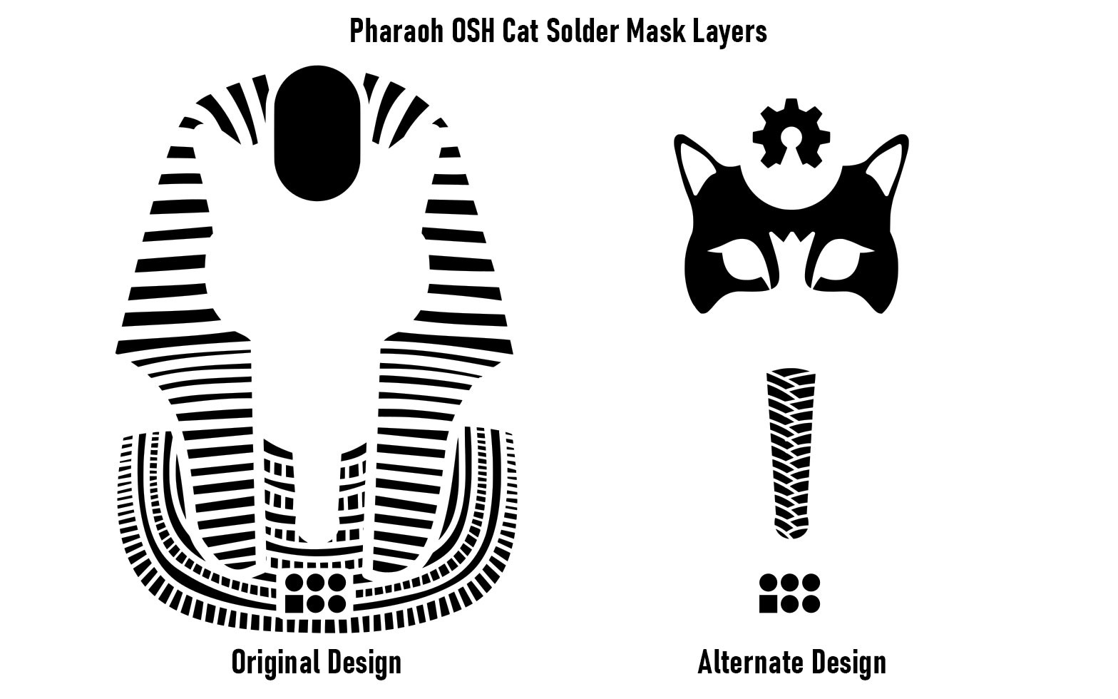
Thanks to OSHPark's addition of their "After Dark" option this once rare combination is now readily available to anyone, and the best part is it doesn't cost more than their normal option! So to prepare you for making your own "After Dark" PCB Art I've updated my "Pharaoh OSHCat" SAO to show off the new characteristics and capabilities of this new option.
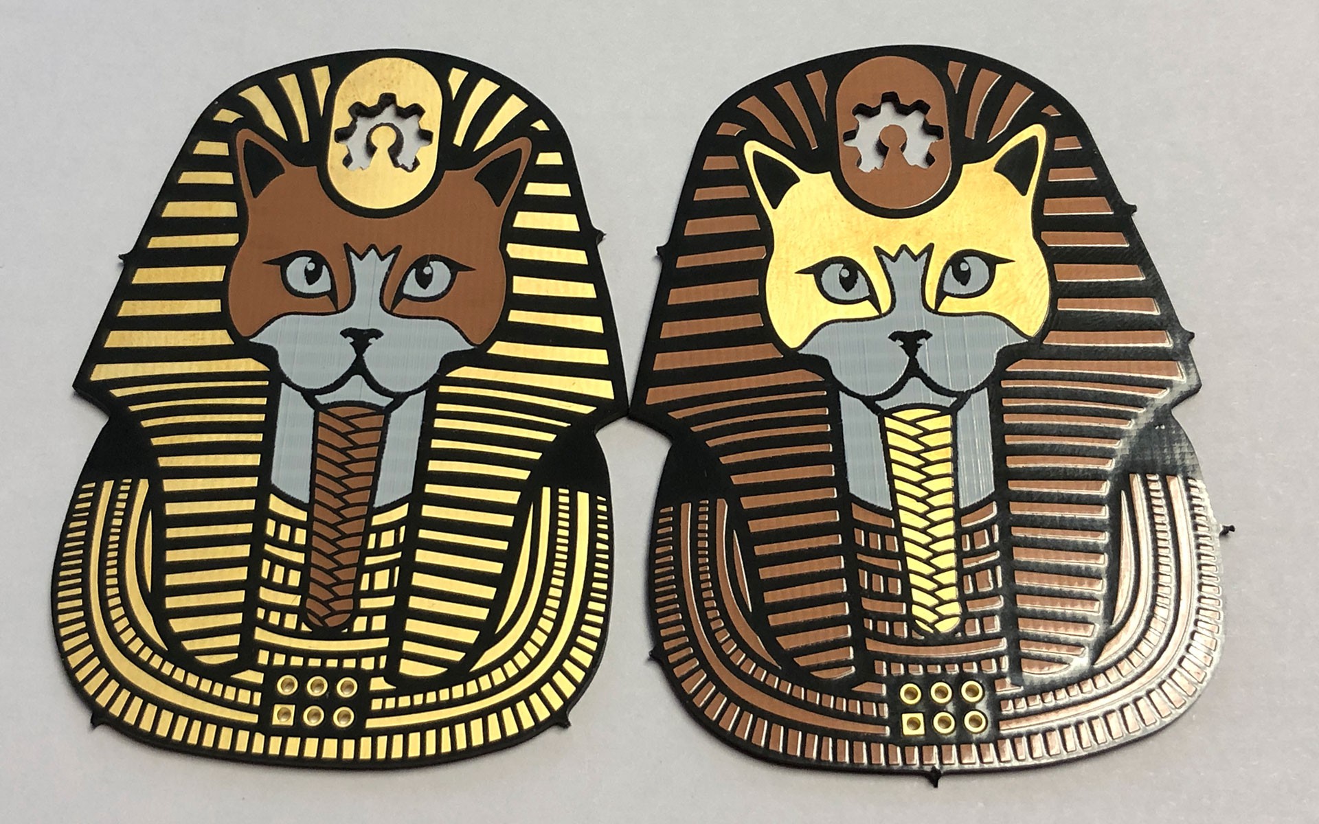
Two "After Dark" Variations on Pharaoh OSHCat Clear Solder Mask
Working with a clear solder mask isn't really any different than working with an otherwise opaque solder mask. Artistically it gives us two colors: Copper, & Shiny Dark Gray. The copper color comes from the copper that is under the clear solder mask. The Shiny Dark Gray comes from the clear solder mask where there is no copper under it.
With most solder masks the presence of the Solder Mask and the Copper layer just means you get a lighter color of whatever the Solder Mask is, the exceptions being Black & White which are completely opaque. With a Clear Solder mask, as the name implies, you see the copper traces almost as if they didn't have any copper finish or solder mask on them. What this means is we can show off the beauty of the copper without directly exposing it and it also still gives us the use of the Copper Finish, in this case ENIG, to create stark contrasts in color.

When designing PCBs, the areas in black on a Solder Mask Layer is where the solder mask is removed in manufacturing. Black FR4
The Matte Black comes from the total absence of the Solder Mask & Copper. Its color and "finish" comes from the bare Black FR4 and its matte color and reflectivity is somewhere between a normal Black Solder Mask and a Matte Black Solder Mask. From an art & design perspective this means instead of just one dark shade of black to work with you get two: The shiny dark gray from the presence of the solder mask, and the very dark black from the total absence of both the solder mask and copper layers. This reflectivity could be used in some creative ways when presented in the right lighting conditions.
Left: Standard Black Solder Mask, Middle: Exposed Black FR4, Right: Matte Black Solder Mask Other than the obvious black color some other differences between Black FR4 and typical FR4 is that Black FR4 does not light up green under UV Light and because it is black it is completely opaque. Because it is completely opaque you cannot use Black FR4 when you intend to...
Read more -
Arc Badge - Part 1: Biting off more than you can chew.
09/09/2019 at 16:43 • 0 commentsArc Badge was born out of failure. Post DEF CON or really any major conference where a lot of creative people are in the same place, you can't help but leave with a dozen sparks of inspiration. Some of those sparks never go beyond the initial idea phase for one reason or another but some sparks grow into a raging fire that will hopefully be used to forge something wonderful. Post DC26 I had "a great idea for a badge". It featured multiple PCBs, lights, sounds, and had a really popular theme. Unfortunately I barely knew how to light up an LED so I had a lot to learn to make it happen and well basically life got in the way and next thing I knew it was almost spring 2019.
The project wasn't where I needed it to be so I shelved it. I decided instead to focus on making a Shitty Add-on Totem for the SAOs I was designing for DC27. I thought it'd be really cool to have a Totem shaped like an Arc Reactor and even cooler if it lit up and could change colors so eventually that idea evolved into Arc Badge.

Here were my design goals for Arc Badge:
- Do Double Duty as a Indie Badge & a Costume Prop
- Be instantly recognizable to anyone familiar with the MCU Iron Man
- Accommodate Two SAOs
- Make the Lanyard easy to Connect & not interfere with the SAOs attached to the Badge
These first two goals were born out of what I liked to do before I started making badges: Making Prop Replicas. The third goal is what made me decide to go with the Avengers Infinity War/Endgame style Arc Reactor. The two "Ears" at the top of the overall triangle shape provided a natural place to have SAO headers protrude from. The final goal was born out of lessons learned from DC26. We had already made changes to the SAO standard so that it was a keyed 2x3 vs a regular 2x2 so we were going to have better overall stability but sometimes SAOs popped off because the lanyard on the badge that was hosting them would knock them off.
Lanyard Placement is very important.
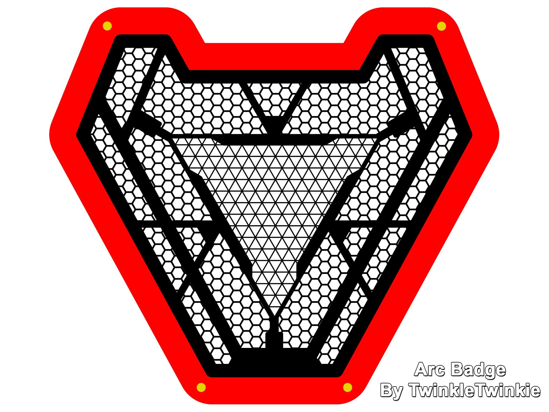
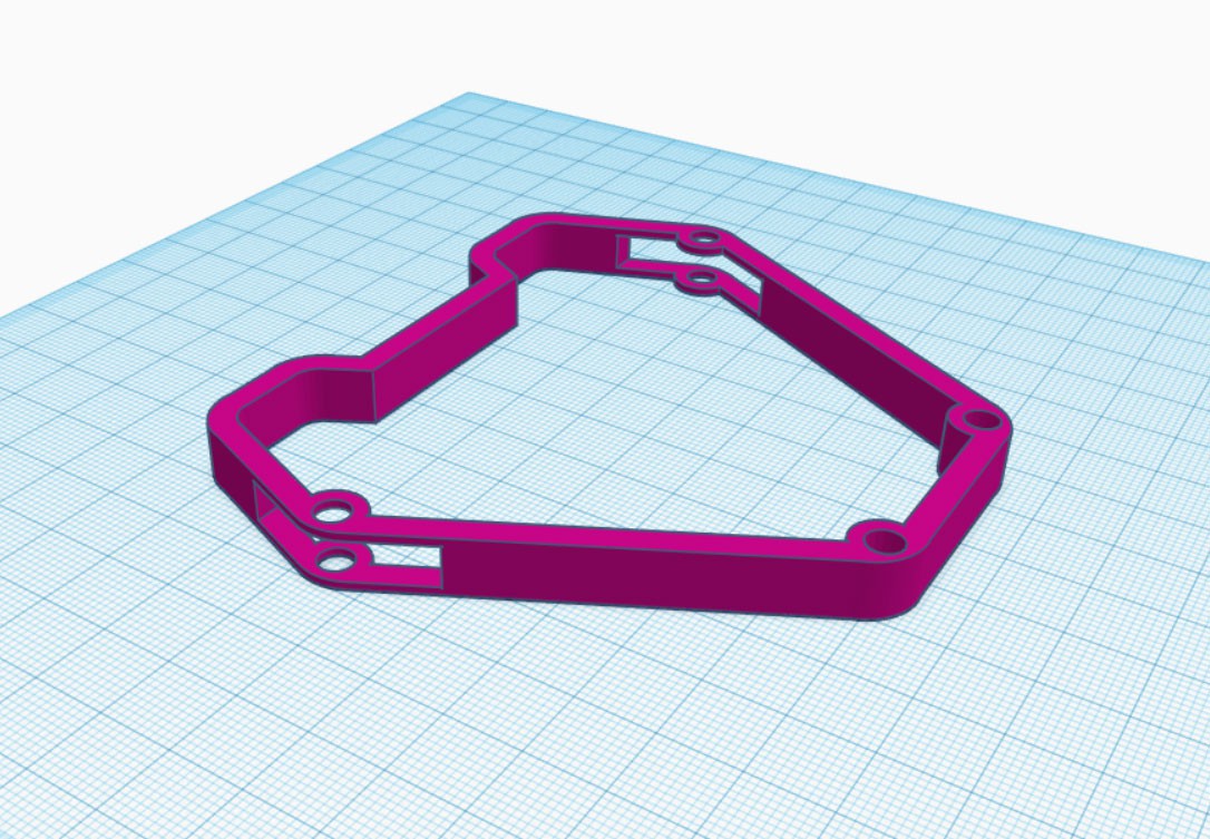
A great deal of thought was put into how the lanyard would connect and where it would be placed. From the picture above you might notice that the two yellow dots indicating where screws would go are not in the correct place. This drawing is from an early concept. I knew that Arc Badge was going to be made up of 3 layers: The top "Art" board, a 3D Printed Spacer, and the bottom board where all of the electronics would actually be.
So working with that I decided the best place to put the lanyard would be on the standoffs that the top board attached to. This greatly influenced how the 3D Printed Spacer would be designed and is actually why it was ultimately 3D Printed vs being laser cut out of acrylic.
For one I could 3D Print them myself on my Prusa MK3, second I could design the model to have cut outs for the stand off so a Lanyard could easily access it and connect to it. I designed the spacers in Inkscape and then pulled them into TinkerCAD to extrude them into 3D and then to cut out the areas where I needed the lanyards to have access to the stand offs. It was important to design the gap to be large enough for the lobster claw to easily clip on and to have some room to move as necessary.

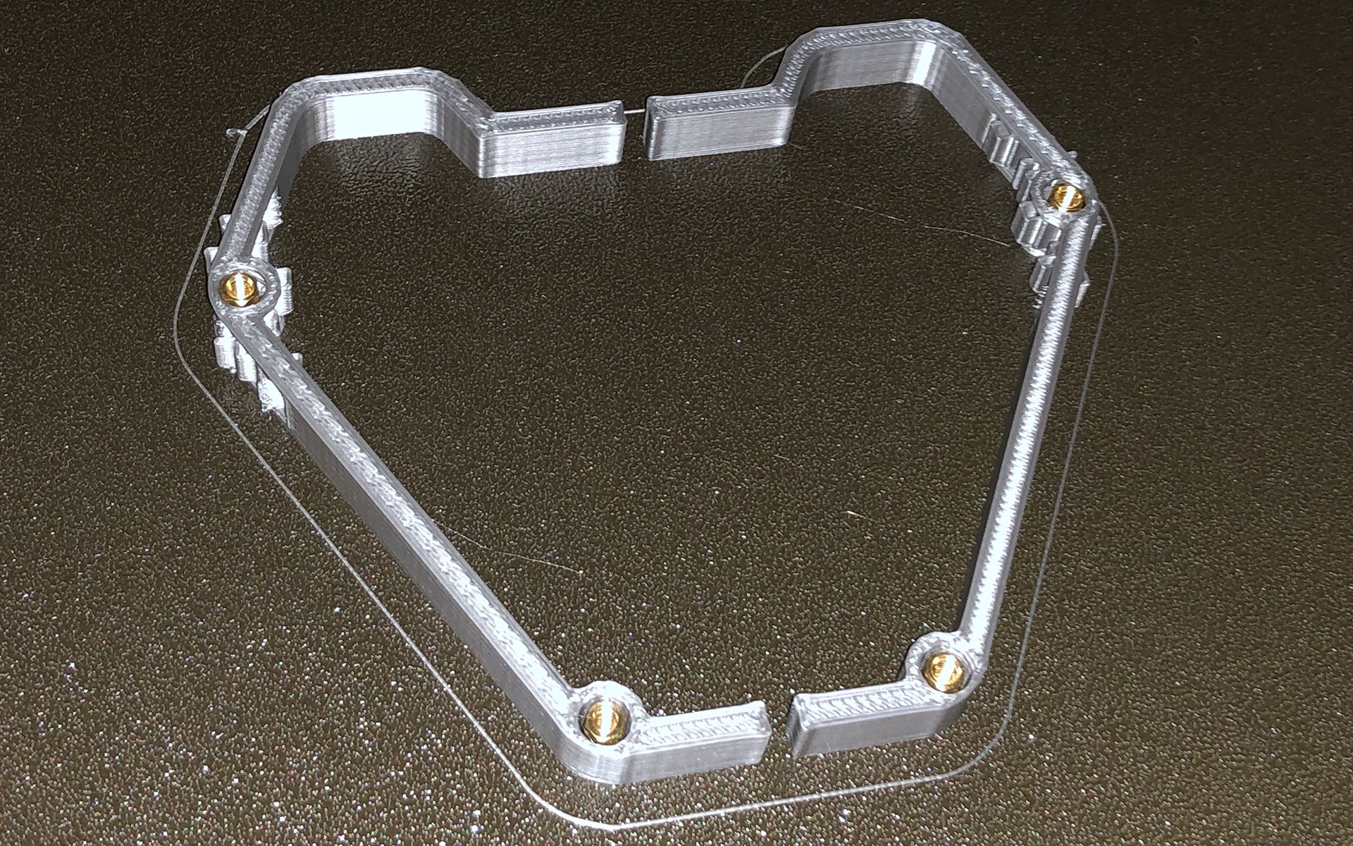
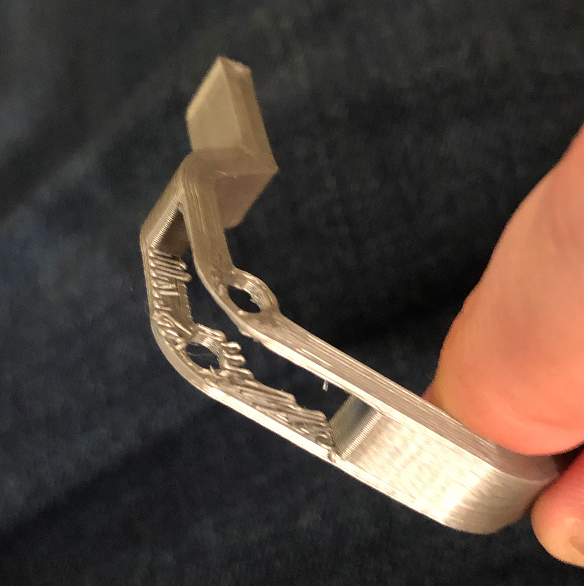
TinkerCAD was used for the 3D Design work on Arc Badge. First prototype spacer. I put in the brass standoffs after it finished printing to confirm I had those dimensions correct. Prototype Spacer showing the gap for the lanyard to connect to the stand off. There were about 1/2 a dozen prototypes of these spacers. You may have noticed from the two pictures above that I started by printing them in halves. This was so that I could print out as many spacers as possible at the same time. I ultimately abandoned the two part design because sometimes where the two parts met they would bow out a little from between the two PCBs. Structurally it wasn't a big deal but aesthetically...
Read more -
Using Side View LEDs in place of Reverse Mount LEDs
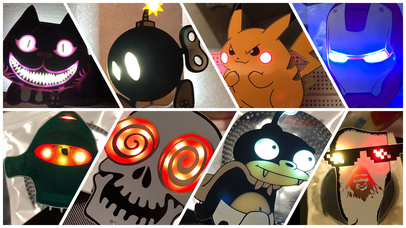
04/11/2019 at 03:15 • 5 commentsSo if you've seen damn near anything I've done for the last 18 months then you've seen examples of using Reverse Mount LEDs and also manually mounting LEDs upside down.

A sample of my projects from 2018, all using reverse mounted LEDs 
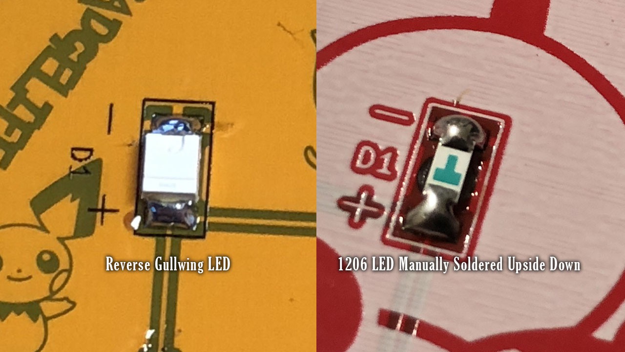
Reverse Gullwing LED & 1206 LED Properly Abused I like shining LEDs through PCBs, it's a great lighting effect and it isn't as harsh a light as you get from having the LEDs on the top side of the board. However there are a handful of draw backs to using them.
Reverse Gullwing LEDs:
- They're expensive.
- "Reverse Gullwing" LEDs are just expensive. Even quantities of 1,000s RGB Reverse Gullwing LEDs are over $0.40/ea as compared to $0.02-0.04 you typically see with a comparable size LED.
- They're exceedingly rare.
- This point is pretty obvious based on the price but there are only about 3 manufactures that make LEDs in this package and only 1 of them makes the RGB variant.
- Minimal light propagation
- If you're putting an LED directly onto the PCB that it's shining through then you only get a circle that is about 9mm in diameter. This varies based on the color, voltage, resistor used etc but in general it's only 9mm and it takes a crap load of LEDs to cover a relatively small area. This only exacerbates the first issue.
Reverse Mounting Normal LEDs:
- Not Pick n' Place Friendly
- Soldering LEDs Upside Down on purpose involves a lot of manual labor and is not solder paste or Pick n' Place friendly, this means it's a solution that does not scale well at all.
- Same Light Propagation Problem as Reverse Gullwing LEDs
So between these two solutions there is the classic "Cheap, Fast, Good, pick two" dilemma. Reverse Gullwings are Expensive, but fast and good. Manually soldering LEDs upside down is Cheap, Slow, but also Good. Now let's look at another solution: Side View LEDs.
Side View LEDs

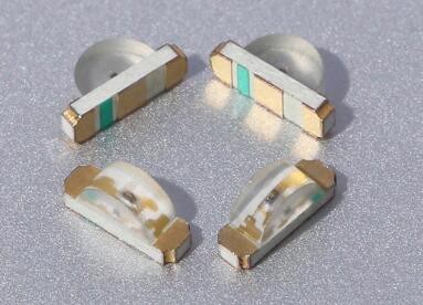
Side View LEDs are exactly what the name says. They're LEDs that instead of shining up or down they shine at a right angle. Side View LEDs are cheap, pick n' place friendly, and you can get them in every standard LED color including UV and RGB. My initial interest in Side View LEDs came from wanting to use the UV variant on some projects to get that eerie glow you get when UV light is shined onto FR4.

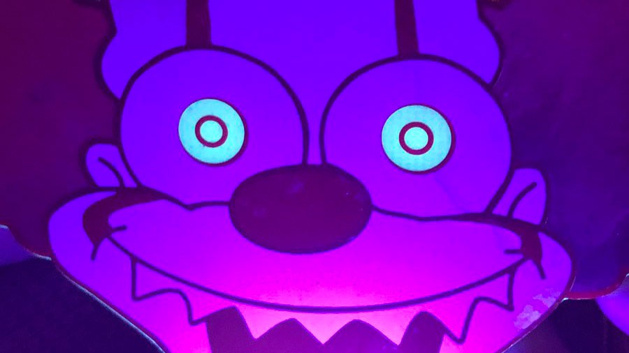
The glowing eyes are from the UV Light, they are not back lit. This is an effect I still intend to use on future projects but I also saw the possibility that I could use Side View LEDs in place of Reverse Mounted LEDs. Unfortunately it isn't as simple as just replacing one foot print for another. Side View LEDs were not designed to be used for this purpose, they're designed to, well, shine light at an angle and are typically used as indicator lights in most consumer applications, think something along the lines of status indicator lights on a Laptop. As such there is a tremendous amount of light bleed that you have to control.
The other major issue with using Side View LEDs is that the light that does shine below them isn't as bright as using a Reverse Gullwing or a typical LED mounted upside down. Due to their vary nature the light they output isn't in a circle it's more like a 1/2 Circle or a very wide cone so you have to rethink your designs to take advantage of that as well.
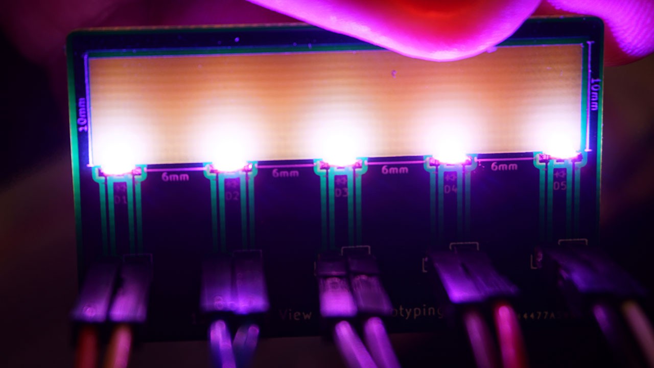
Pink Side View LEDs I designed a simple prototyping board so that I could get measurements and figure out how to best work with these LEDs before I put them in a project. I am very glad I did this because despite having seen other examples of Side View LEDs being fantastic drop in solution for back lighting PCBs I instead found it had its own draw backs.
- Uneven Lighting
- So this is similar...
- They're expensive.
-
SAOv1 to SAOv1.69bis Upconvert Tutorial
03/21/2019 at 01:57 • 1 commentWhen we were working on the SAOv1.69bis "Standard" a primary goal was to maintain backwards compatibility. This is great for everyone who collected so many SAOs from DC26. A major upgrade for v1.69bis is mechanical stability added by using a Keyed Shroud and a matching Keyed Female connector on the badge. Based on the bulk order I recently placed I believe most of the Independent badges will have Keyed Female Badge connections. To best take advantage of these changes I've put together this Up conversion tutorial.
This tutorial will address two scenarios:
1. SAOv1 without the 2x2 Header Soldered on.
2. SAOv1 with an existing 2x2 Header Soldered on.
If you need to buy some 2x3 Headers for this project here is an non-sponsored link to the listing I purchased mine from on Amazon.
This tutorial does not require any desoldering!
Scenario 1. - No Headers
If you some how still have a SAO without any headers soldered on then the solution to your problem is easy: Remove the 2 left most pins.

Then solder the header on with the "Arrow" on the top pointing towards the "VCC" mark on the SAO.
That's it, you're done.
Scenario 2. - Headers Already Soldered On
This situation involves a little more work but is still very easy and doesn't require any soldering or desoldering at all!
Here is what you need:
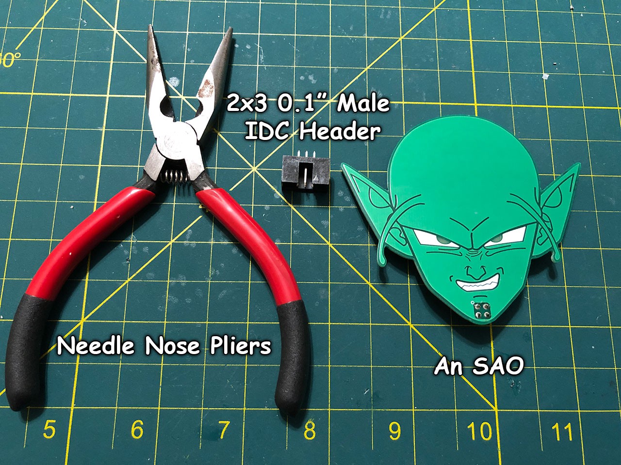
- A Pair of Needle Nose Pliers
- 1x 2x3 0.1" Pitch IDC Header (Shrouded Male Header)
- Your SAO

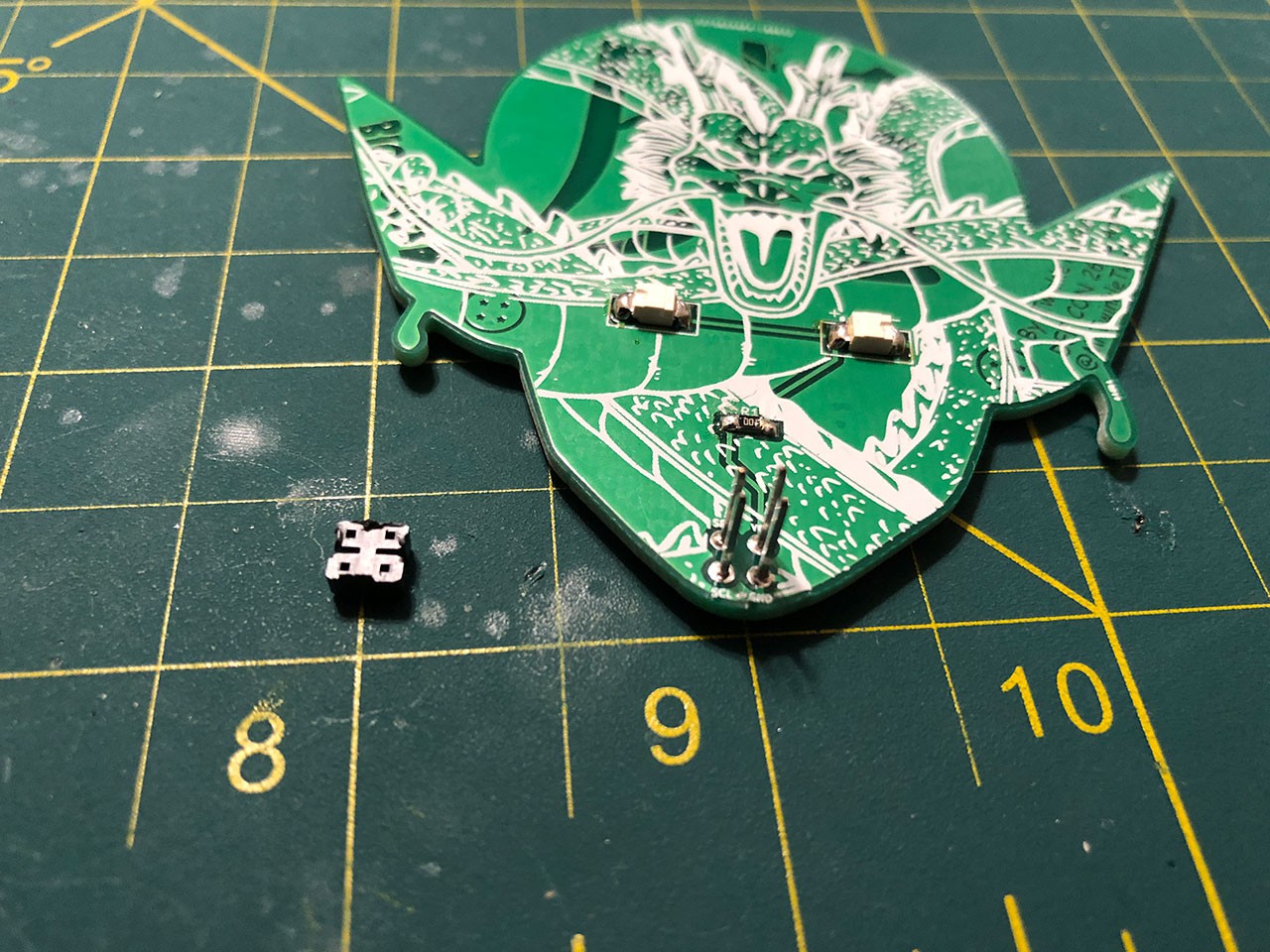
Step 1. Remove the Spacer
The first step is to remove the plastic spacer on the SAO Header. Using your Needle nose pliers clamp onto the header and just pull straight off. If you have a Surface Mount SAO Header instead of through hole you might want to use a hair dryer or heat gun to heat up the plastic first so you don't rip off the contacts.

Grip only the plastic and pull up, do not twist! 
v1 SAO with Plastic Spacer Removed Step 2. Remove the pins from the 2x3 Header
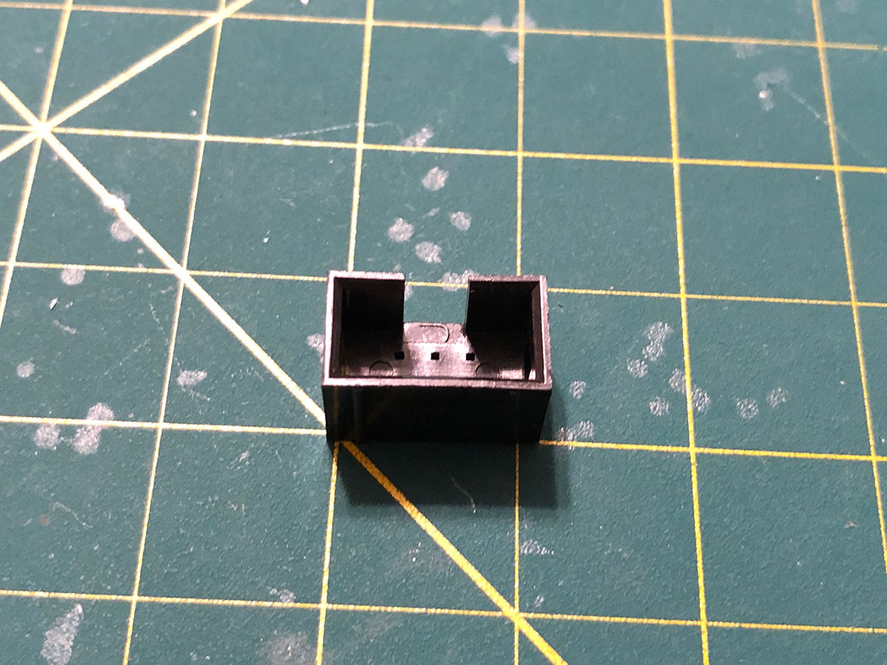
Pretty self explanatory, Using your needle nose pliers remove all of the pins from the 2x3 IDC Header. Don't twist or anything just grip the pin tightly and pull away.

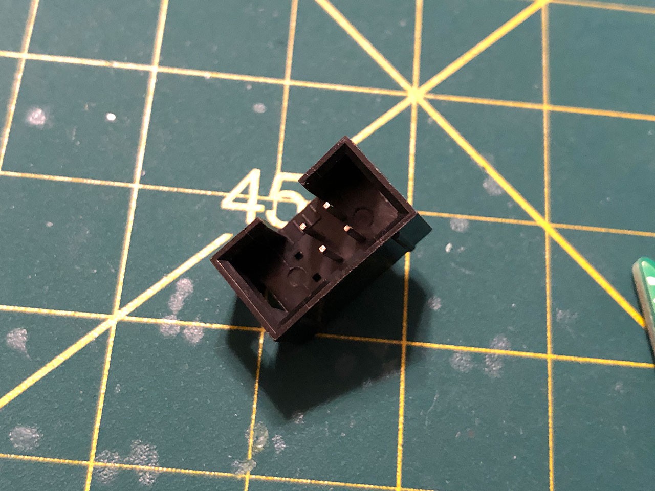
2x3 0.1" IDC Shroud With Pins Removed Step 3. Slide the 2x3 Shroud on top of the 2x2 Pins
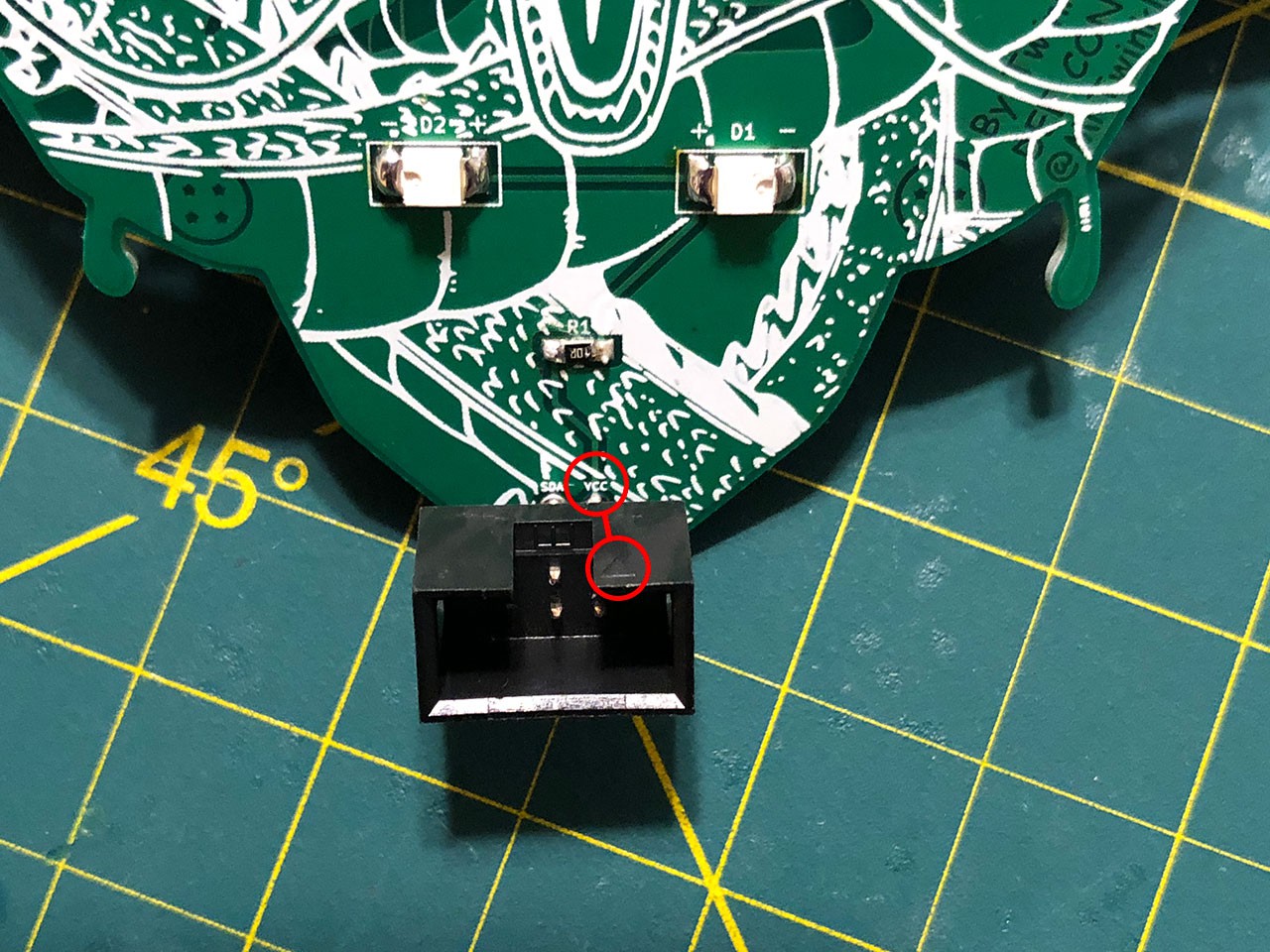
Slide the 2x3 Shroud on top of the 2x2 Pins with the "Arrow" on the shroud pointing towards "VCC" on the SAO. If your SAO isn't labeled it should be the top right pin.

The Arrow Should Point at the Top Right Pin 
A Completed SAOv1.69 Conversion Step 4. Test your SAO & Enjoy
Finally, plug your SAO into your badge of choice and make sure it functions as it should. Being that you didn't have to desolder anything it should work just fine.

Big Green on the Queercon 15 Badge -
My DEF CON 26 Talk Notes
08/11/2018 at 19:35 • 0 commentsUpdate 10/04/2019 - Getting to Blinky 5.0
Contextual Electronics just updated their tutorial series to KiCAD 5. I recommend that you start here.
https://www.youtube.com/watch?v=BVhWh3AsXQs&list=PLy2022BX6EspFAKBCgRuEuzapuz_4aJCn
[This area is out of date, leaving for posterity.]
Getting To Blinky 4.0
https://contextualelectronics.com/courses/getting-to-blinky/
This is where I recommend everyone start for learning KiCAD. It's an entirely step-by-step tutorial that gives you the foundational knowledge required for using KiCAD.
Keep in mind this Tutorial was written for KiCAD 4.0 and KiCAD 5.0 is a little different. I would recommend installing KiCAD 4.0, following Chris's tutorials, do a couple of simple projects for fun, then upgrade to KiCAD 5.0. Chris is working on an updated 5.0 series but if you want to start now that is what I would recommend.
[/end of out of date]
svg2shenzhen Inkscape Extension
This is the plugin that I talked extensively about and use a great deal for my projects.
https://github.com/badgeek/svg2shenzhen
How I make Shitty Add-ons
This is the stream I did in June on how to make SAOs.
PCB Color Reference Spreadsheet
This applies only to PCBWay, and is only meant to give you a rough idea of what to expect.
https://docs.google.com/spreadsheets/d/1dmkTsKZDV5iltQbpEa_QOL5XYEONms_M1ZETBNO5ub4/edit?usp=sharing
-
Dealing with a Massive Shitty Add-on Failure
06/06/2018 at 19:41 • 5 commentsI fucked up. I fucked up 250 Shitty Add-on boards. Those 250 boards and the 300 I ordered to replace them, replacement parts, and solder reworking station cost me more than half my overall Badge Life expenses this year. To give you an idea of how much that is, I'm currently measuring those expenses in the thousands. I am not Kickstarting any of my projects, I am not crowdfunding them and I am not sponsored in any way, that money comes directly out of my pocket and it's a cost I have to swallow.
I fucked up, and I'm here to share with you how I fucked up so that you can learn from my mistakes, of which there are many.
Background
So let's get this out of the way. I am not an Electrical Engineer, nor am I a Software Developer. I don't have a job that has anything remotely involved in designing PCBs and the only time I use a soldering iron or work with electrical schematics is at home. The only kind of electrical circuit I know how to design off hand is a super basic LED Circuit. Everything I know I have learned from Websites, YouTube Videos, and wisdom shared by friends who know far more than I do. The sum total of all of this is that I am a n00b!
I got into PCB Design, or specifically PCB Art, because I love PCB Art and I spent the majority of the beginning of 2018 learning KiCad (Benchoff wouldn't get off my balls about Fritzing) and learning how to manipulate it to spit out boards it was never intended to produce.
This is all a recipe for disaster.
What I Made
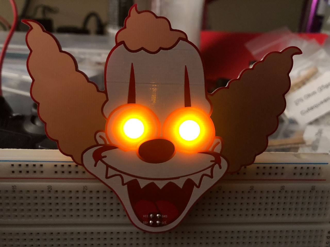
With the introduction of the Shitty Add-on Connector I decided to abandon previously planned projects for DC26 and focus on making Shitty Add-ons (SAOs) for Indie Badges. I already had one project that was nearing completion (The Freeman) so I completed it and started on my path to making SAOs that were Shitty in name only. My first project was "Krusty the It".

Krusty the It Krusty the It got a massive response on twitter. In a very short order I went from next to no followers to dozens of followers. Twitter has played a big part in my motivation to participate in Badge Life, there are few communities that are as great as the Twitter Badge Life community is. The response was so immense that I decided to order another 100 boards to supplement the original 50. This gave me the opportunity to make some minor tweaks and to order another SAO and save money on shipping.
The design of my SAOs are only made up of 4-5 Components. The original design was 2x LEDs, 1x Resistor, and 1x SAO Connector. When I found that the resistor dimmed the LEDs too much I removed it in the first board revision that I sent to the fab. This would prove to be one of many fuck ups.
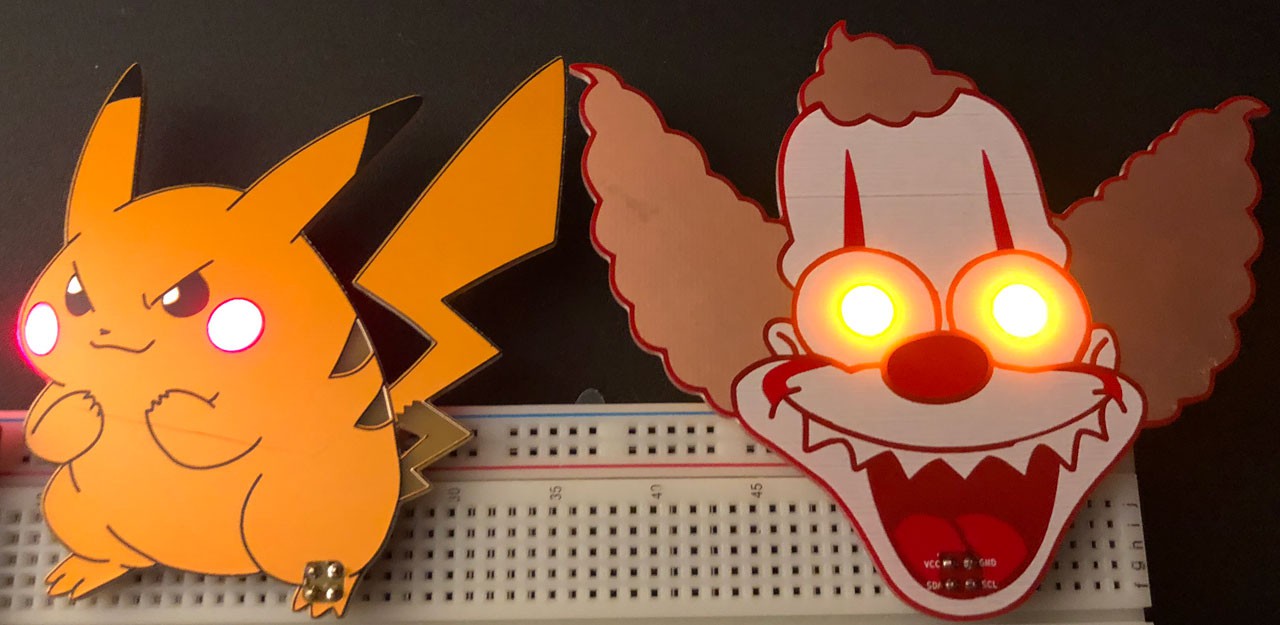
After I got my boards back from PCBWay I immediately soldered one together and shared it with the world at large on twitter. This would be the introduction of "Fat Pika". A kind friendly alternative to "Krusty the It" after getting feedback that many people loved Krusty but it would scare the shit out of their kids.

Fat Pika & Krusty the It After getting Fat Pika in I moved forward with assembly of "Krusty the It". I personally soldered all of the boards over a weekend and shared my results with testing and prepping them to be packed for DEF CON. I was very excited and thrilled to be more than 1/2 way done with my SAO assembly efforts....
Read more

