-
Getting back into it ... (IT WOULD BE NICE IF HACKADAY HAD AN API TO CREATE PAGES AND PROJECTS)
12/30/2022 at 14:43 • 0 commentsHey there,
It's been a while since I posted anything to hackaday.Over three years, in fact, since October, 2019.
I still haven't found a good pipeline to allow me to create projects on github, and then denormalize the content to hackaday, youtube, and thingiverse.
It is very time consuming to put it all on github, then produce youtube videos and thingiverse pages for each project, and then use hackaday for the final presentation.
Nonetheless I have continued doing projects continuously since my last post. Some of those projects have been well documented on github, and even on youtube, but even there I have fallen far behind, only taking a very limited set of projects that I completed public, while some very interesting projects, due to dependencies on some private source code, and/or pure laziness, have not been publicly revealed or documented.
I am going to try to remedy that by focusing on documentation, and avoiding new projects for a while.
That means that you will (hopefully) be seeing some projects presented here that took place a while ago, and the date-time stamps on the projects, and pages here on hackaday will not be representative of when the projects actually took place.
My goal is to try to get caught up a bit, so that I meet the basic goals of presenting open source projects on github and thingiverse and using hackaday and youtube to nicely present them in a more entertaining manner.
So, please bear with me as I work through the process. I will be thinking about a good way to maintain all of this documentation.If anyone has a good way to automatically generate hackaday pages and projects, something I could run against my github readme files which would generate the basic info on hackaday, that would be handy.
Same for thingiverse ... I'd like to present my 3D printing and laser cut stuff there, but have it driven from readme (MD) files I create and put on github.
*** IT WOULD BE NICE IF HACKADAY HAD AN API TO CREATE PAGES AND PROJECTS***
LOL, that might become a project of it's own :-)
Thanks,
- Patrick
-
Help matching impedances
10/15/2019 at 22:51 • 3 commentsHey there!
I'm looking for some help in understanding impedance matching. I'm hoping one or more of you technically savvy electronics folks will jump in and give me a simple circuit recommendation.
Specifically I want to try to build a passive "pad" that goes between the output of a Fishman Prefix Plus built-in guitar pre-amp and the input of an IRig HD2 guitar-audio-to-usb converter. My issue is that, as it stands, I have to turn the volume control of the pre-amp as close as I can to it's minimum value (like 0.01, which is iffy), and set the gain of the Irig input hard to it's minimum value to get any kind of decent sound. Anything else results in lots of distortion. I'm trying to get a clean guitar sound.
https://www.fishman.com/products/series/prefix/prefix-plus-t-onboard-preamp/
https://www.ikmultimedia.com/products/irighd2/index.php?p=specs
I get the feeling that by using the extreme lowest setting on the pre-amp I am not in the sweet spot of the pre-amp design. I feel like it makes the sound tinny ... I'm always lacking bass when I use the device (compared to just plugging my guitar into the Yamaha Stagepas PA). It's just my noob idea that the amp was probably designed to be used in the middle, rather than at the extremes of its gain settings.
So, I'm thinking about making a passive "pad" that basically consists of two resistors.
input    O------- R2 --------+----------------O output
                             |
                             R1
                             |
ground  O------------------- +----------------O ground
My basic, very limited, understanding is that such a passive pad consists of a voltage divider created by resistors R1 and R2. I really have no idea what values to use, although I sort of think their ratios should be about 9:1 where the value of R2 is about 9 times greater than the value of the "shunt" resistor "R1". Rather than just guess, I thought I would ask the community.
The specs for the devices are copied from the user manuals Here is what I see:
FISHMAN Guitar Pre-amp
- Nominal Input Level: -20dBV
- Input Impedances: 20MOhm
- Output Impedance: "Less than 3.5kOhm"
- Nominal Output Level: -12dbV
IRIG HD2 audio-to-usb converter
- Maximum Level: from 307mvpp to 8.36Vpp
- Gain Control Range: 28.7 dB
- Input Impedance (guess): 380 kOhms
I cannot find the actual input impedance specification for the IRIG HD2. There is a reference in the user manual that it is a "high-Z input". I am guessing it is simllar to the input impedance for the IRIG2 which IS specified as 380kOhms.
----------------------------------------------------------------------------------------------------------------------------------
So, given those specs, what should be the values of R1 and R2?
Any other thoughts on what I'm trying to do here? I'd sure like to get a good sound and a feeling of control instead of a tinny sound and a pre-amp that is turned down to 0.01 ....
Thanks in advance for any replies.
- Patrick
-
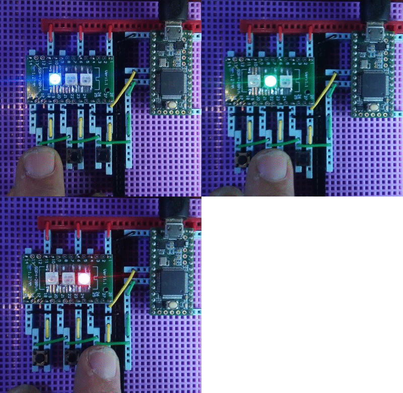
Why doesn't someone make a WS2812b Switch Array?
09/07/2019 at 06:17 • 9 comments![]()
Two things:
- I can’t believe this worked (almost the very first time) !
- I’m surprised nobody else seems to have done this before !
OK. I have been looking for months on the net for somebody, anybody, who has combined WS2812b addressable LED’s with switches to create a switch array. At the end of this I explain why I would want such a thing, but for now just please understand that I could not find any other examples of anyone selling, or even trying, something, like this.
Perhaps no-one needs it, or perhaps it exists, but is just not on the web, but perhaps no one has thought of it before. In any case, it seemed to me that it would be fairly straightforward to combine a switch with each ws2812 in an array (or a strip), and be able to tell which button is pressed, if any, based on the timing of the signals being sent to the LED’s.
Now please understand that this is very crude hardware and code. I didn’t even expect it to work. The LEDs are supposed to have capacitors from power to ground, most schematics recommend a resistor from the output pin of the Teensy to the input pin of the LED, and I’m pretty sure that no electrical engineer out there would recommend hooking the DIN (data in) pin of each LED through only a switch directly to a bus line to an input pin on the Teensy. Something has to fail, right? Oh, and always use a separate power supply for the ws2812’s lol 😊
So, please let me say that I will appreciate any comments, or contributors, that can design a proper circuit, help me to understand how it should work, and/or really want to dig in to write good code for this purpose.
CIRCUIT BOARD
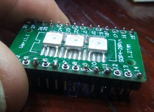
I have a couple of ws2812 arrays sitting around (an 8x32 and a 4x4), but I don’t have any strips. That’s a shame because the strips look like you can easily cut one off and work with it. You probably have a strip you can just cut up! I don’t want to cut up the arrays, but I do happen to have a bunch bare ws2812 LEDs that I bought experiment with. So I rummaged through my stuff and found a little circuit board I could solder them to. That being about my third try to air-solder SMD’s, I glued them on with superglue, a little too much in one place, and then glommed some paste solder on em with a toothpick, and blew hot air on em. Even though it was only 215C, I basically tortured the LEDs as I had to burn through the superglue on one of the contacts. Nonetheless, they conduct electricity, and there are no shorts.
![]()
I added some pins to the board, so then I had three ws2812’s I could play with on a breadboard. If you want to build one of these, you probably can just cut one off a strip and use alligator clips or whatever it takes to hook them up.
The first circuit I made used jumper wires. Much to my surprise I hooked up the 5V and ground and got the Teensy example basic ws2812 test program working with my little 1x3 array of LEDS in a few minutes,.
So then I decided to try to write some code to make it work as a switch array.
THEORY OF OPERATION
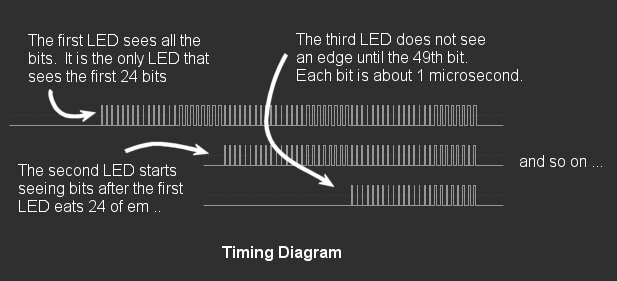
As you send serial data to the LEDS (actually, to the first LED’s DIN – data in - pin) using the ws2812 protocol, each LED takes 24 bits to display an RGB value. OK, actually it’s GRB, but that’s not important!
After the first LED “eats” the first 24 bits, it starts passing the remaining bits onto the next LED. So the second LED does not see any bits (rising edges) until the first LED is done with those first 24 bits. Then the second LED “eats” the second 24 bits before it starts passing the remaining bits to the third LED, and so on.
![]()
The other thing worth knowing is that each bit in the ws2812 protocol, both ones and zeros, has a HIGH and a LOW part. ...
Read more -
Everything looks like a (plastic) nail ..
09/02/2019 at 19:27 • 0 commentsTo a man with a hammer (3d printer) ... everything looks like a (plastic) nail …
OK. Whew.
Turns out that 3D printing is addictive. Who would have thought? It’s been about a month now since I got my (first, only) Prusa MK3s printer. I’ve pretty much been running it, or doing Fusion 360 design projects, 24/7 for the entire time. My sleep patterns are out the window, watching the sun rise as I wait, sleepy eyed, for a 3D print to finish before crashing for a few hours to wake up at noon, 1, or 2 and start again.
To say this has been a minor digression from the project would be an understatement.
I got it, basically, because I know at some point I’ll want a custom box of some kind for the system components. I also got it because I have an inkling of an idea for creating different kinds of floor controllers, ala a mouse-pad for your feet, or gyro-accelerometer gesture detection shoes, or something like that.
To whit I’ve also built quite a collection of little gyro-accell modules (ADXL345’s and MPU6050’s), a bundh of esp8266 modules, and have even got a collection of Velostat, conductive fabrics, threads, copper tapes, and the such with, once again, the general idea of creating a controller of some kind that is more portable, and expressive than four shiny metal push buttons on a metal box.
But what I didn’t expect was how the 3D printer would take over my life.
I think I’m over the initial hump. As I’m writing this I’m also learning how to post things to Thingiverse. So I posted this: https://www.thingiverse.com/thing:3837992 .. a system of brackets and fixtures for making desk, table, and wall mounted 12V LED lamps.
![]()
I don’t want them to be part of my hackaday.io page, per se, but in this case I at least want to note why there has been no activity on the project for the last month.
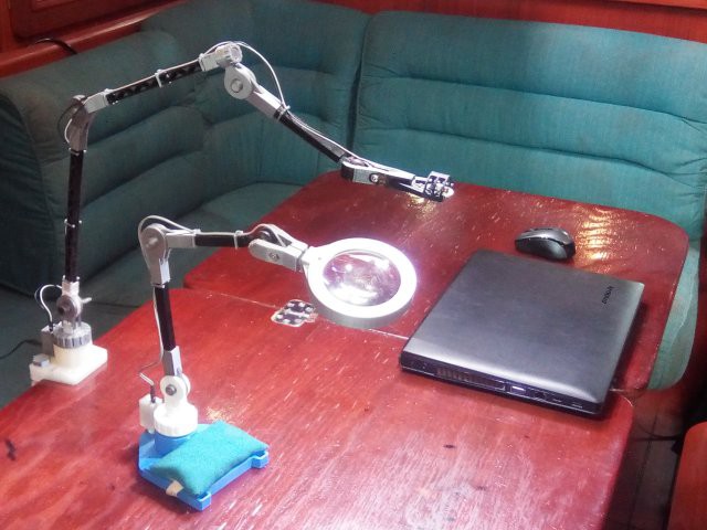
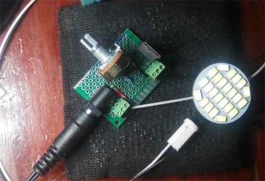
That’s because not only is it obligatory to print the basic examples, then design your own phone case, but it is almost compulsary to add lights, and an rPi, to the Prusa. So while learning Octoprint, Fusion 360, and 3D printing in general, I ended up creating this whole darn fangled 10mm lighting system, not only for the Prusa, with a 12V dimmer circuit (ok, maybe this is a subproject), but also as a clamp on desk lamp, and a desktop magnifying lamp as well.
Here's the 12V dimmer I made for the Prusa:
![]()
Sheesh, for some reason I ended up thinking about CNC, and want to have one of those little CNC machines, maybe hook my Dremel up to it, now.
![]()
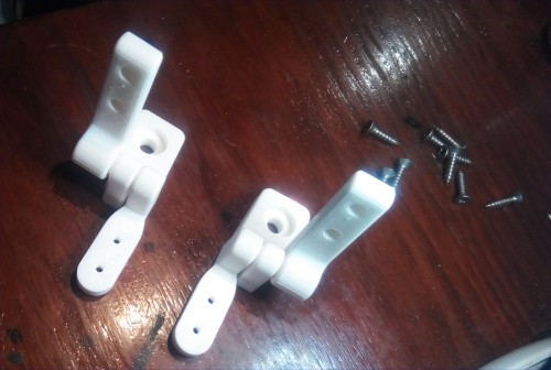
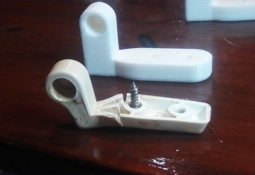
I guess the other thing I hadn’t realized was how appropriate a 3D printer is for life on a sailboat. Instead of keeping a bunch of spare parts, it is conceivable that many things can be 3D printed on demand. I discovered that early in the first week … Had some toilet hinges that were broken … there was a darned set of STL files for the exact model of my Jabsco toilet on thingiverse! I downloaded it, sliced it, printed em, and they’re better than the original hinges from the manufacturer (who tried to save plastic and they characteristically break in the same place).
![]()
Anyways, it’s been almost a month and only now am I semi-ready to start going back to the electronics. I had to get a new Audio Injector Octo board because the I2C stopped working on the one I had, so I had just diverged into the Zynthian project, got blown away by that, and was also messing with the 8266-gyro stuff. I chatted with Flatmax, and got 4 CS42448 chips (like $10 each) and will try replacing the chip on the bad board (my first SMD soldering try, esp with 64 pins), so I think the first thing is going to be to go back to the AI Octo Rpi Bare Metal setup, test the new board, and then try to fix the old one.
But I had to put something up about the stupid 3D printer. I’m waiting for thingiverse to render an STL file, I think, and then I can upload the 30 or so...
Read more -
OK, but seriously ... Hackaday Reorganization
07/24/2019 at 19:25 • 5 commentsI have a pretty good idea now how hackaday.io works. My first three months have resulted in a hodpodge of projects, pages, log entries, and links to a bitbucket repository. Although I would like to salvage what I can from those projects, pages, log entries, and repositories, I feel it is now time to kind of "start over" to provide a better framework going forward.
The most important Hackaday "thing" is the now published link to the rPi bare metal vGuitar rig hackaday.io project and my three (3) followers :-)
Besides that, my general profile serves as a master container for subprojects and pages, and that entry point will also be retained going forward.
(1) I need to move the source code, generally out of Bitbucket and into GitHub. Why? I think I might trust Microsoft more than Atlasian, and I just feel like GitHub will be here for sure, going forward.
(2) Add lots of readme.md's to the GitHub project and subdirectories. Why? Because I like the idea of providing static or semi-static contextual information for the source code at the directory level. In fact, I am not thrilled with using Hackaday.io for the long term preservation of static information about the source code, how to build it, etc. I like the idea of information that is keyed to the commits I make, as the structure, semantics, and usage of the code is a moving target and can change over time. Hackaday does not lend itself to versioning, it seems better for recording snapshots of a moment in time, and presenting them in a separate linear context. i.e. as a fixed index into the morphing github commits.
(3) Create GitHub "pages" for the long term documentation of the architecture, components, APIs, etc, in the project(s). Why? this is a tough one. Mostly because they are a natural fit for linking from the readme.md's in the source repository directories and subdirectories.
Although in a sense I like the hackaday.io "editor" functionality, and the ability to upload images to their servers, etc, I sometimes find it constraining. Even if I try to use the <> raw HTML feature, it is just the nature of WYSIWYG html editors that they stomp on the HTML and create lots of artificial constraints on the presentation. One thing that I have always struggled with, even in pure html, is to get two images to present side by side with a caption underneath each. It can be done in html, but I would be afraid to do it in the hackaday.io editor for fear that that it will get stomped on in some round trip to html and back. I had a heck of a time just getting the bullet list on my history page to work consistently. The editor seems to want to make it's own decisions about the font faces and attributes of the text and does not change well between outdended (no bullet list) and indented (bulletted) items. It's not a slam on hackaday. I've written these kinds of WYSYWIG editors and they are not easy and always iffy somewhere around the edges.
(4) Use hackaday to present the most visually appealing aspects of what I'm doing. I think hackaday.io serves as a great entry point for people surfing the web looking for interesting things to look at. I think there is still a role for hackaday "pages", like this one, for extemporaneous stream-of-consciousness writing.
I like the eye candy of hackaday.
If anyone else was interested in joining the project, perhaps that is what hackaday would be best at. Unfortunately (a) no one has expressed an interest, and (b) I'm wary of inviting people because a one-person project gives me ultimate flexibility. In order to properly move to a multi-person project, a LOT has to be established between the players ... from coding conventions to areas of responsibility to processes and procedures. I think I ...
Read more -
Pi Circle to Teensy Audio Shield and Quad Audio device
06/19/2019 at 03:11 • 0 commentsI added the AudioControlSGTL5000 object to my port of the Teensy Audio Library available at https://bitbucket.org/phorton1/src-circle/src/master/ This is, of course, just part of my ongoing rPi bare metal vGuitar Rig project, but I felt like a “page” would be the best way to present this information.
![]()
These classes allows one to connect a Teensy Audio Shield, or other SGTL5000 to a Raspberry Pi within the bare metal Circle environment.
It turned out to be a little more difficult than I originally thought it would be. The sgtl5000 / teensy shield absolutly requires an input MCLK. For 44.1khz sound, that clock has to run at 11.289Mhz. Here’s a handy snippet of code to produce an 11.289 Mhz clock in Circle:
LOG("starting MCLK",0);
u32 freq = SAMPLE_RATE * 256;           // 11289600
u32 divi = CLOCK_RATE / freq;            // 44
u32 modi = CLOCK_RATE % freq;           // 3257600
u32 divf = (modi*4096 + freq/2) / freq; // 1182
    // printf("divf=%d should equal 1182\n",divf);
    // the above math overflows 32 bits
divf = 1182;
m_MCLK.Start(divi, divf, 1);
There is no good way on the Pi to generate 3 synchronized clocks, the other two being needed are the the BCLK (bit clock) and FCLK (frame clock, also known as the LRCLK). The bcm2835 PCM peripheral can, as a special case, generate a synchronized FCLK for a given BCLK, so it can usually act as a master to i2s devices, but for the sgtl5000, which requires a 256fs master clock, it just cannot reasonably be programmed to act as an i2s master.
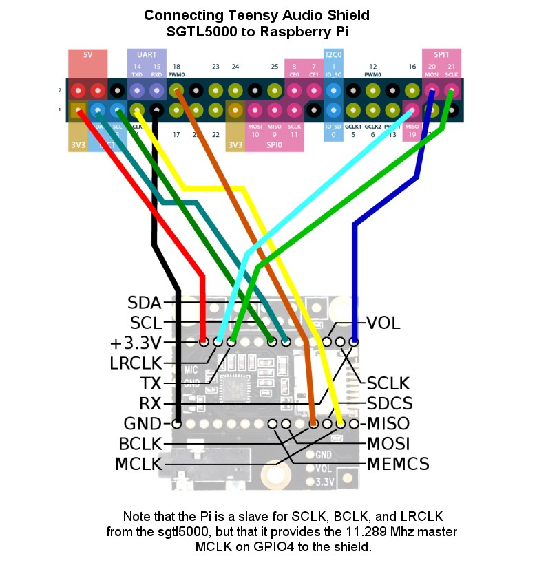
So, instead, my code for the rpi generates the 11.289Mhz MCLK on GPIO4, sends it to the sgtl5000 (teensy audio shield), which then acts as the i2s master, generating the BCLK and FCLK signals based on that. And therefore, in Circle, the AudioControlSGTL5000 is actually not implemented, and you must use the AudioControlSGTL500slave device instead.
![]()
It works ok, however, and so is worth checking in.
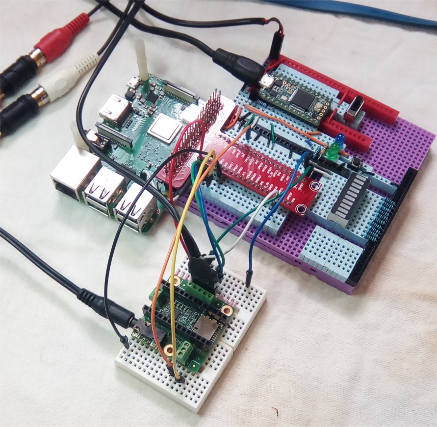
Below is a diagram showing the pin connections between the Raspberry Pi and the Teensy Audio Shield. Note that this is *just* the Teensy Audio Shield … there is no Teensy running the codec … it is connected directly to the Pi.
![]()
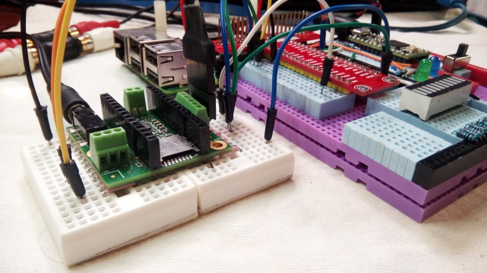
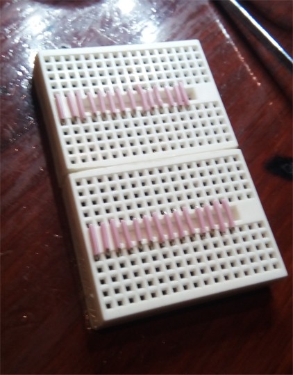
I made a simple breadboard for the Teensy Audio shield by gluing two of the small standard breadboards together (after sanding the joining edges to remove some space), and running jumpers. This allows me to just use regular wires to connect things. I HATE DUPONT FEMALE CONNECTORS !!!
![]()
Circle TeensyQuad device
I also added two additional new classes, AudioInputTeensyQuad and AudioOutputTeensyQuad to the library. These allow the Pi to be connected to a Teensy that is actually running an existing Teensy Audio Library program, so the Pi can act as a (relatively larger, big
brother) audio co-processor to the Teensy.The teensy MPU has two i2s modules (as opposed to the one on the bm2835) that run synchronously. Paul has created the AudioI2SQuad input and output devices to allow two teensy sound shields to be stacked for quad io.
These classes allow you to easily use any rPi, including the zero and 3B+, as a DSP co-processor to a teensy audio application. It *may* even allow you to retrofit such an additional processor into your existing Teensy audio application with a minimal set of changes.
 +-------------------+      teensy       +--------------------+
 |   Teensy Audio    |   quad channels   |       rPi          |
 |    application    |      2 & 3        | acting as an audio |
 |    using quad     | <===============> |    co-processor    |
 |    audio device   |                   |                    |
 +-------------------+                   +--------------------+
      ^        |
      |        |      teensy quad
      |        v     channels 0 & 1
     IN       OUT
The teensy quad device channels 0 and 1 are used for the main audio input and output, from a mic or line input, out to line or the headphones. The teensy quad device channels 2 and 3 are used to communicate with the rPi.
From...
Read more -
There is really only one project ...
06/02/2019 at 06:49 • 0 commentsThis page attempts to present a history of my experiments with embedded systems, starting with my first Arduino projects. I intend for this page to be more-or-less a living document, kind of like a log summary across my projects. It will be updated at points in time. It is not intended to be stream-of-consciousness, blog-like writing
MY PROJECT HISTORY
First Arduino Circuits
Foot Pedal test
HIDUINO USB device early experiments
USB Host Shield Library
usbHSLHostExample
Max3421E
myUsbHostExample
myUsbDeviceExample
myUsbPassThruExample
First Teensy Circuits
Broken Softstep II
Teensy Logic Analyzer
myCL2 library
extract firmware from midi sysex file
reflash Softstep II
Teensy USB devices
Denormalized Teensy USB Library
teensyStandardDevice
teensyMyDevice
teensyPassThruDevice
Teensy Audio Shield 1
-
Initial Tests
teensyLooper1
First SD Card Looper
teensyLooper2
Initial LoopControl breadboard
First rPi boot - Raspian (rPi 3b+)
rPi Bare Metal Beginnings (rPi zero)
dwelch
devenv
console.pm
Initial rPi reboot circuit
SREC bootloader
Initial Komodo integration
rpiSerialMemory
rpiParallelMemory
Placid
XMODEM bootloader
Komodo Integration
Initial Circle work
Windows Build
devenv
Ethernet TFTP bootloader
Komodo Integration
Circle Bootloader
FATFS read and write kernel
my Binary Serial Protocol
bootcode.bin probe
Build System and recoveryN.img
Teensy Audio Shield 2
-
Circle I2S
myAudioDevice
rPi zero to teensy i2sQuadDevice
teensyLooper3
devolved to a test program for I2S
rpi3B+
Sound Injector (my wm8731)
rpiLooper1
teensyControlBoard 2
Circle Bluetooth
initial testing
denormalized source
rewrite
HCI
L2CAP
SDP
RFCOMM
Audio Injector Octo
rpi breadboard gadgets
my (aborted) rpi breadboard gadget
teensyHeadphoneAmp
- rpi breakout breadboard 2
- teensyPi 2
- port Teensy Audio Library to Circle
- figger out and implement driver for AudioInjector Octo
Initial Integration
- UGUI user interface - initial "Recorder" demo
- implement ili9486/xpt2046 touch screen Circle Device
- begin writing my own wsWindows, a cross between UGUI and wxWidgets
- adxl345/esp8266 & arduino accelerometer experiments
- basic wsWindows working, start adding system events (Midi, Audio notification) ...
- Quck and Dirty Zynthian in preparation for porting? fluidSynth to Circle)
- ....
NOTES:
Ultimately, everything I am doing is related to my goal of creating a rPi Bare Metal vGuitar Rig. On hackaday, that project will contain my commitments to the architecture and design of the rig, and will likely reference a number of specific sub-projects that add levels of detail about the pieces and parts that make up the full rig. The full project, I believe, will be too complicated to present in it's entirety in a single hackaday project. So for the rPi Bare Metal vGuitar Rig, I envision a number of pages and projects that will, when taken as a whole, explain the final thing that I (hope to) create.
"There is a road ... it's not a simple highway ..." (Robert Hunter)
Along the way there have been many other "projects", and there will likely be many more, that, although related to the rig, are not, technically speaking, a part of it. There are twists and turns on the path to the finished product. There are experiments, or series of experiments, that I have, or will perform, in order to learn about a specific technology and to generally learn about and test things that *might* be used in the rig. Sometimes I have to learn, the hard way, that something that I thought...
Read more -
reset(); initialize();
05/24/2019 at 18:32 • 1 commentI am just getting started with Hackaday and am learning how to present the information I want to present.
I'm not sure what's what at this point, so am starting by "adding a page". I'm believe this "page" is associated with my profile (not with a specific project), and so is probably the most general stuff, in nature, that I can type.
I suspect this constitutes my profile-associated stream-of-consciousness, real-time "blog". Similar to what I might write on Facebook, there are a series of "pages" that are topical to whatever I happen to want to talk about at a given point in time. It *might* reference projects, sub-projects, repositories, or other web-pages of my own or other folks, and parts of it *might* be project specific, or not.
Associated with each project are a number of structures, including a "Details" box, and
- Files
- Components
- Logs
- Instructions
- Discussion
I'm not sure how to best use these. I have already started the "Details" box, but I don't think what I typed there is appropriate. I think "details" is a single set of text and would be best served as a brief presentation of the highest level architecture of the system. I feel like "Logs" or "Discussion", and even references to external "Files" are probably more appropriate for keeping a history of the project and/or providing more rigidly structured information like detailed architectures and designs.
I do know that I want to document this journey. Both my personal emotional and day-to-day feelings and situations, as well as providing a more stable and static technical presentation and discussion of the pieces and parts of it.
From this page, I feel like I need to try each of the above things "Files thru Discussion" and see how they work.
... Patrick

