JRodrigo
-
Testing the prototype 1 ¡FAIL!
06/03/2018 at 19:24 • 2 commentsWhen I tested the prototype, as I already expected, it was impossible to maintain a stable communication via I2C when the rotor turns around.
The positive part is that the power via "SD pins" was stable with some capacitors, maybe using a couple more of SD pins gets a more stable voltage.
-
First board design
05/14/2018 at 22:22 • 1 commentFor the first board design I opted for a basic design, like a breakout board. Once the prototype works correctly. But in the future the best option is to integrate a microcontroller to get the measurement and control the motor speed, obtaining this data via I2C, SPI, ...
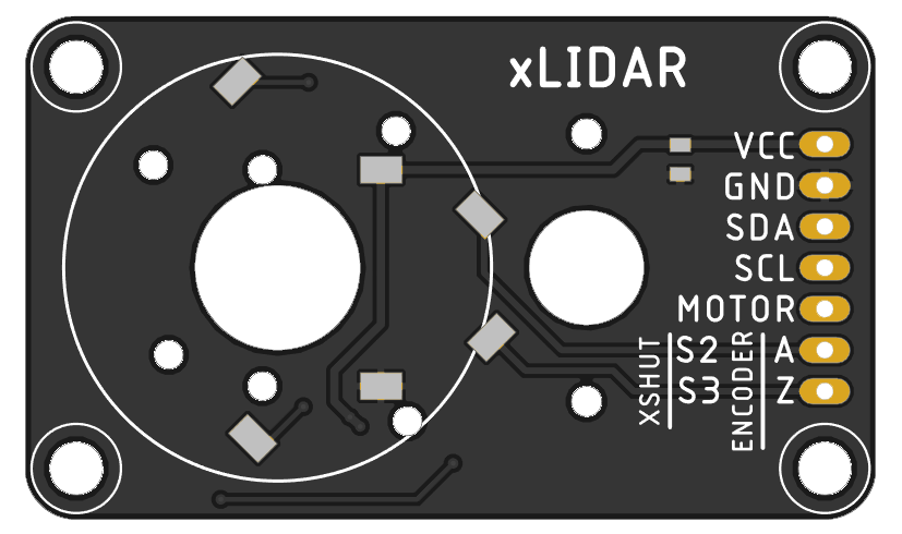
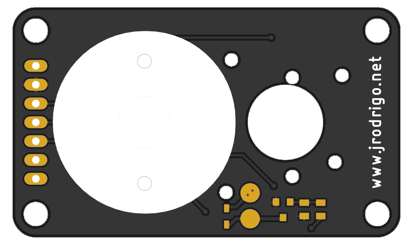
Main board breakout
It's just a board with a MOSFET to control the motor speed and a pin header for the signals. To carry the rotor signals (VCC,GND,SDA,SCL,XSHUNT+ENCODER) I'm going to use the pins from a SD card slot.
![]() ---------- more ----------
---------- more ----------![]()
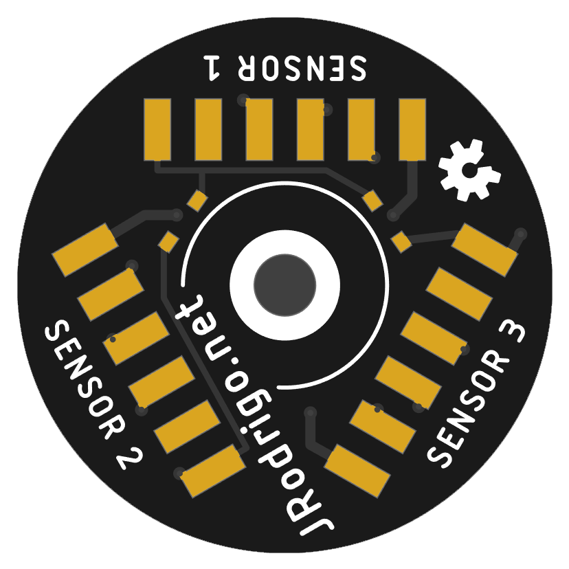
Top rotor for 3x VL53L0X ranging sensor
I have implemented the encoder and the zero position using the same XSHUNT signals. When the sensor initializes, the I2C addresses are configured using XSHUNT signals, after that this signals are used as encoder (to control the speed) and the zero position.
![]()
![]()
Source files
The boards are designed with Eagle 9 without schematics because I designed the board directly without it. But I will make them if this first revision works as expected =)
xLiDAR
Affordable and open-source LiDAR based on 3x VL53L0X ranging sensor