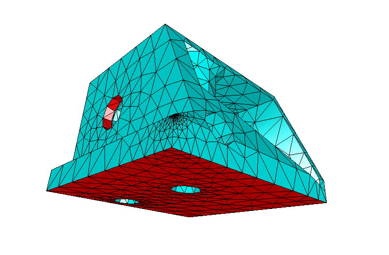
I'm looking at one version of the laser diode housing that will use 3D printed sintered aluminium, with the minimum of material to reduce costs.
The following design is a first pass that should have sufficient material for both supporting the focus tube, fixing bolts, thermocouple recess and providing sufficient thermal coupling for the diode.
Researching open source thermal FEA packages as an alternative to the commercial packages, lead me to ELMER which is a multi-physics solver capable of solving all sorts of problems.
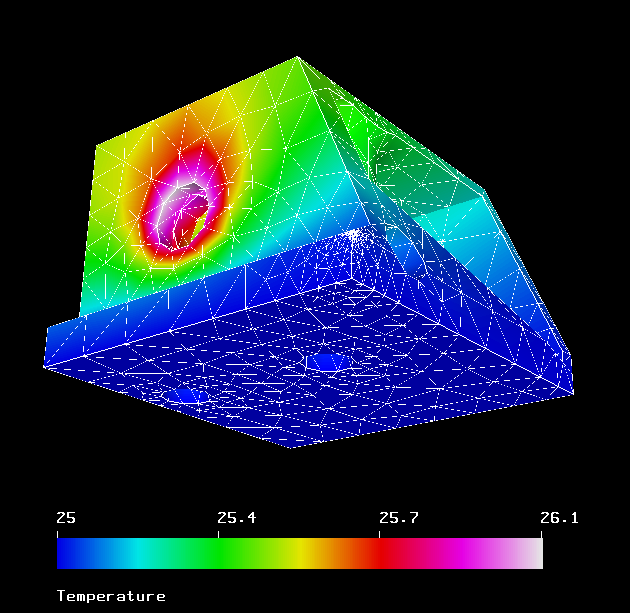
The diode block was imported and the temperature of the TEC face defined as a heat boundary condition of 25'C and the diode interface ring defined as heat boundary condition with a heat flux of 2.1W over the area of the selected faces.

Running through gave the following results, which show that the diode block provides sufficient material to dissapate the generated energy of the diode. And the diode temperature will be approxamtly one degree higher than the TEC set point.

The following snippets for Elmer are firstly to scale the model from millimeters to meters
Coordinate Scaling = Real 0.001
This section is setting the temperature of the face adjacent to the TEC to 25'C
Boundary Condition 1
  Target Boundaries(1) = 28
  Name = "TEC-temp"
  Temperature = 25
End
This section sets the diode interface heat flux (thermal load entering the system)
Boundary Condition 2
  Target Boundaries(2) = 17 21
  Name = "diode-heat"
  Heat Transfer Coefficient = 237
  Heat Flux = 1.734e5
End
 David Brown
Discussions
Become a Hackaday.io Member
Create an account to leave a comment. Already have an account? Log In.