-
!Abandoned! - Please see project description at top of page
11/07/2018 at 02:28 • 1 commentas above
-
Frame coming together
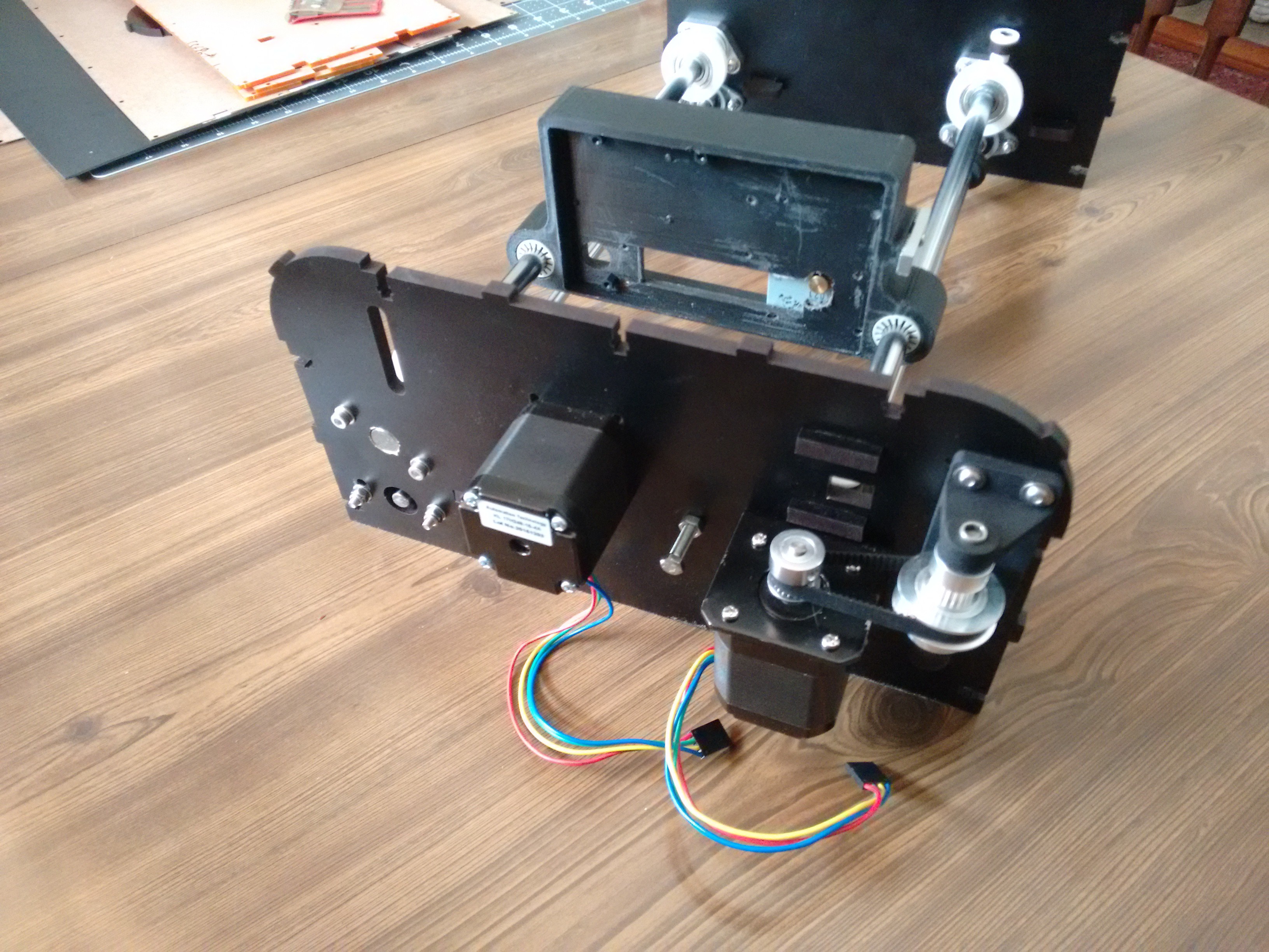
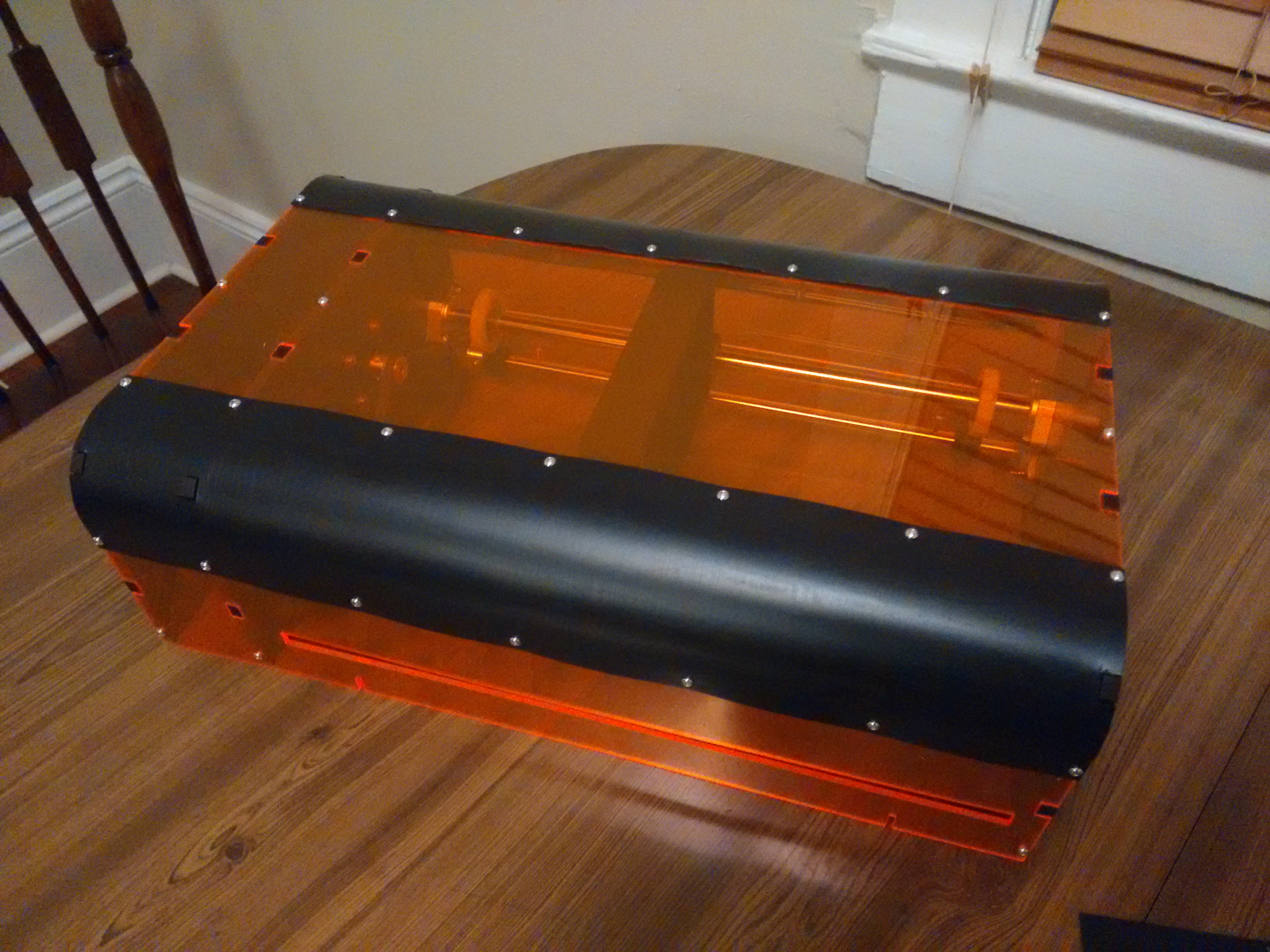
04/14/2017 at 22:05 • 0 commentsi thought I would share some (poor) photos of the frame coming together.
![]()
![]()
I've added an idler pulley to take up a little slack and increase the angle of contact on the driving cog.
On the electrical side i'm planning on bypassing the FIFO and using an atmega to generate signals, and cutout the raspberry pi zero. This is because I know that the current design iteration is not up to the job, but will be useful for running experiments that will allow development to continue. I'm more familiar with AVR for programming so that will make setting up data logging etc. for tests easier.
I'm also considering ways to get funds to allow faster development time. Where I am at the moment, I don't think there is scope for the likes of kickstarter as its not yet at the functional prototype stage. Patreon may be an option, but I have only glanced at their site. Any thoughts and comments welcome.
Edit - Put the casing plates together; it's nice when tolerance gaps work correctly.
![]()
-
laser head buildup
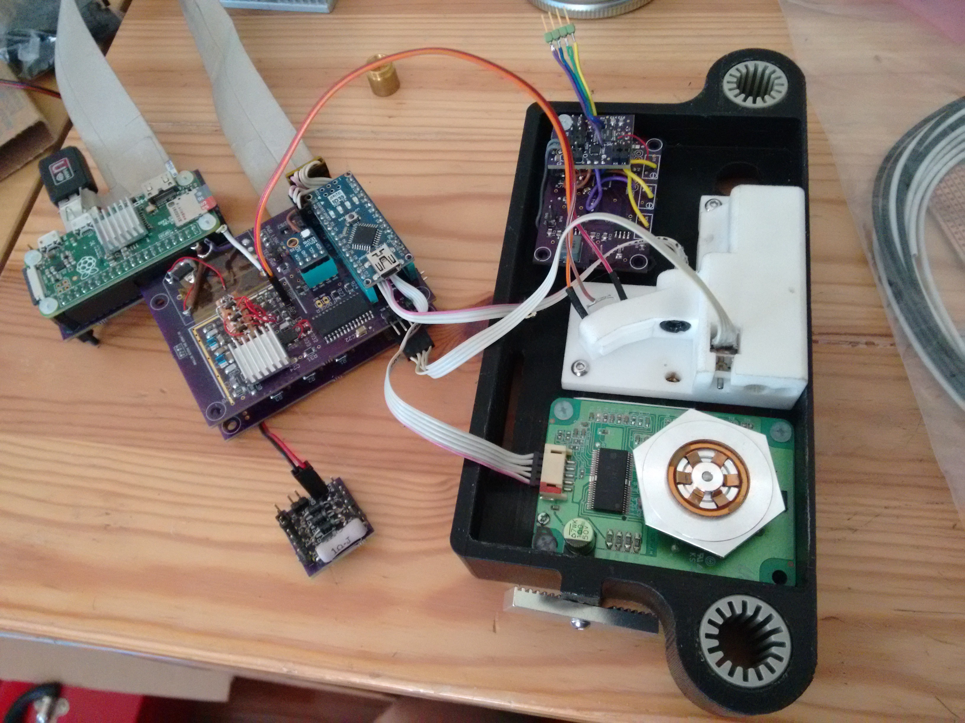
04/06/2017 at 15:53 • 0 commentsI've received the 3D printed parts, so i've been building up the components of the laser head. The high definition nylon prints are good, but dissapointed by the large black casing as its not a solid print so fitting the metal screw inserts has been a pain. For the cost next time i need larger scale parts i'll just invest in a printer and do it myself.
I'm still awaiting some more nuts & bolts to assemble the frame
![]()
The trigger laser now works and will be trimmed by having leading zeros in the FIFO to allow accurate position calibration.
![]()
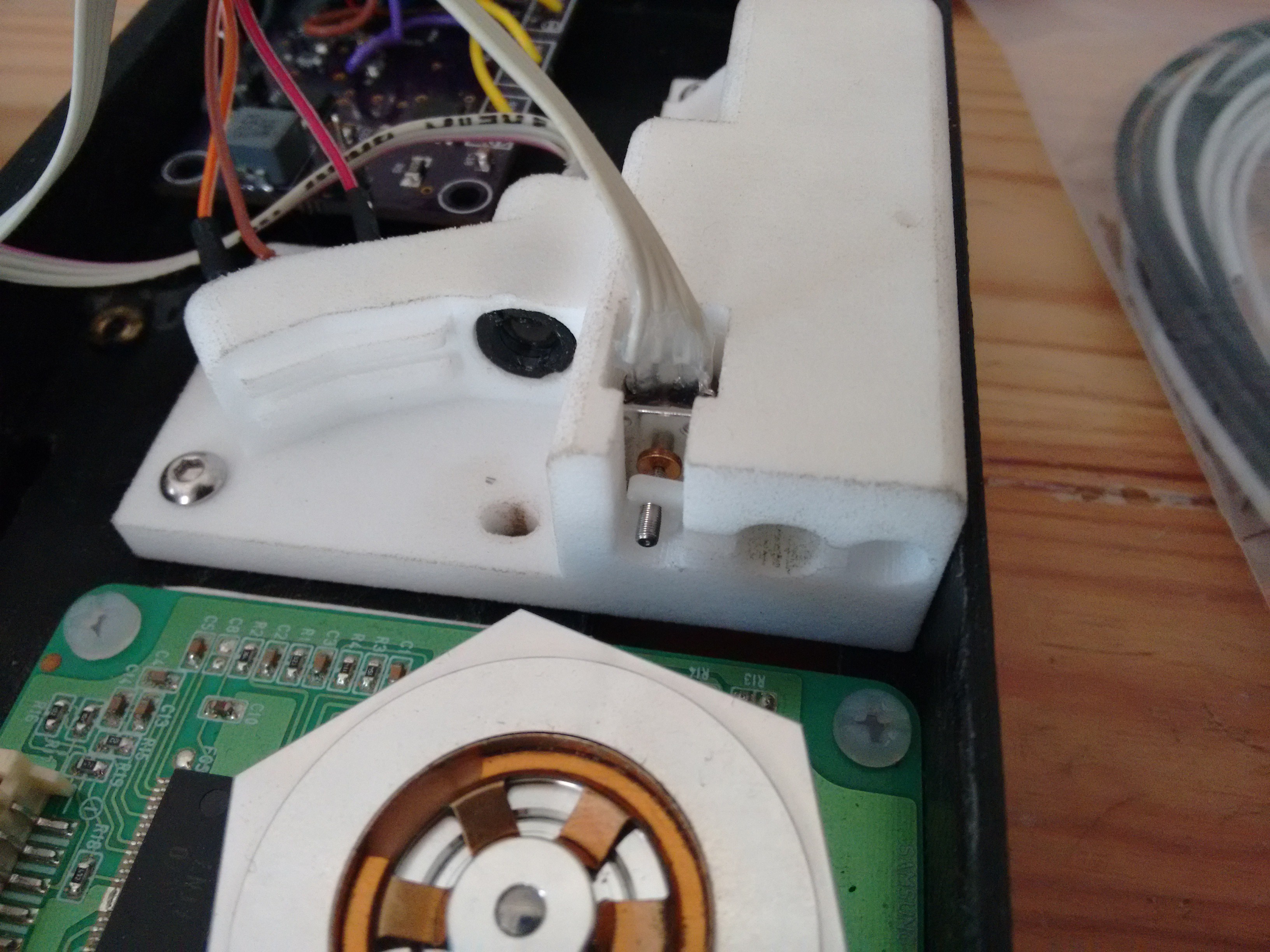
The micro stepper fitted well and will do a good job allowing the focus to be adjusted. I've yet to fit the beam tube and output lens.
-
Ordered the printed parts
02/05/2017 at 16:37 • 0 commentsSo i've placed an order for the printed components so those should come through from Shapeway next month, and i'll get the cut parts ordered shortly.
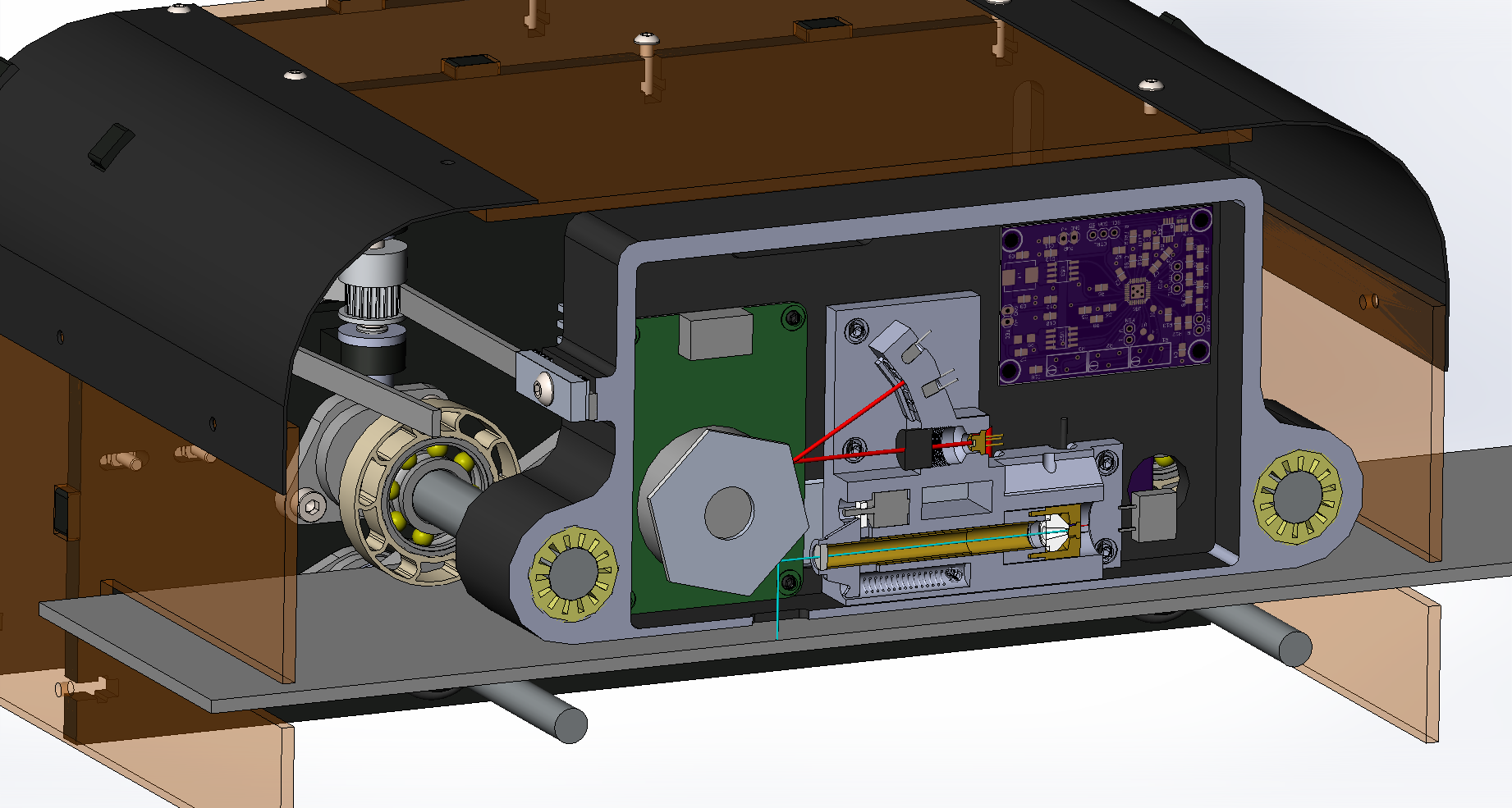
To give an overview of where this is at here are some cut-away, firstly of the print head;
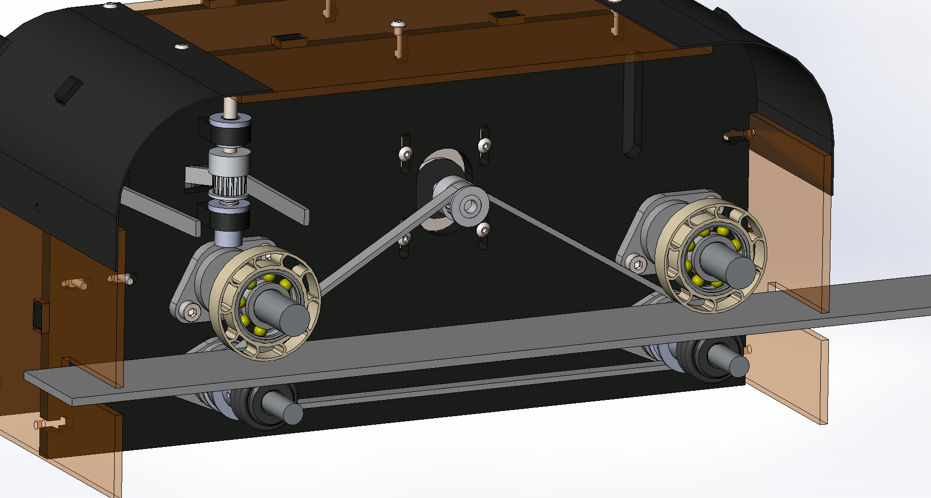
Then the base plate drive system, onto which the paper is taped down. This is likely to be a piece of tempered glass, which can be easily cleaned of any chemical contamination build up from the papers;
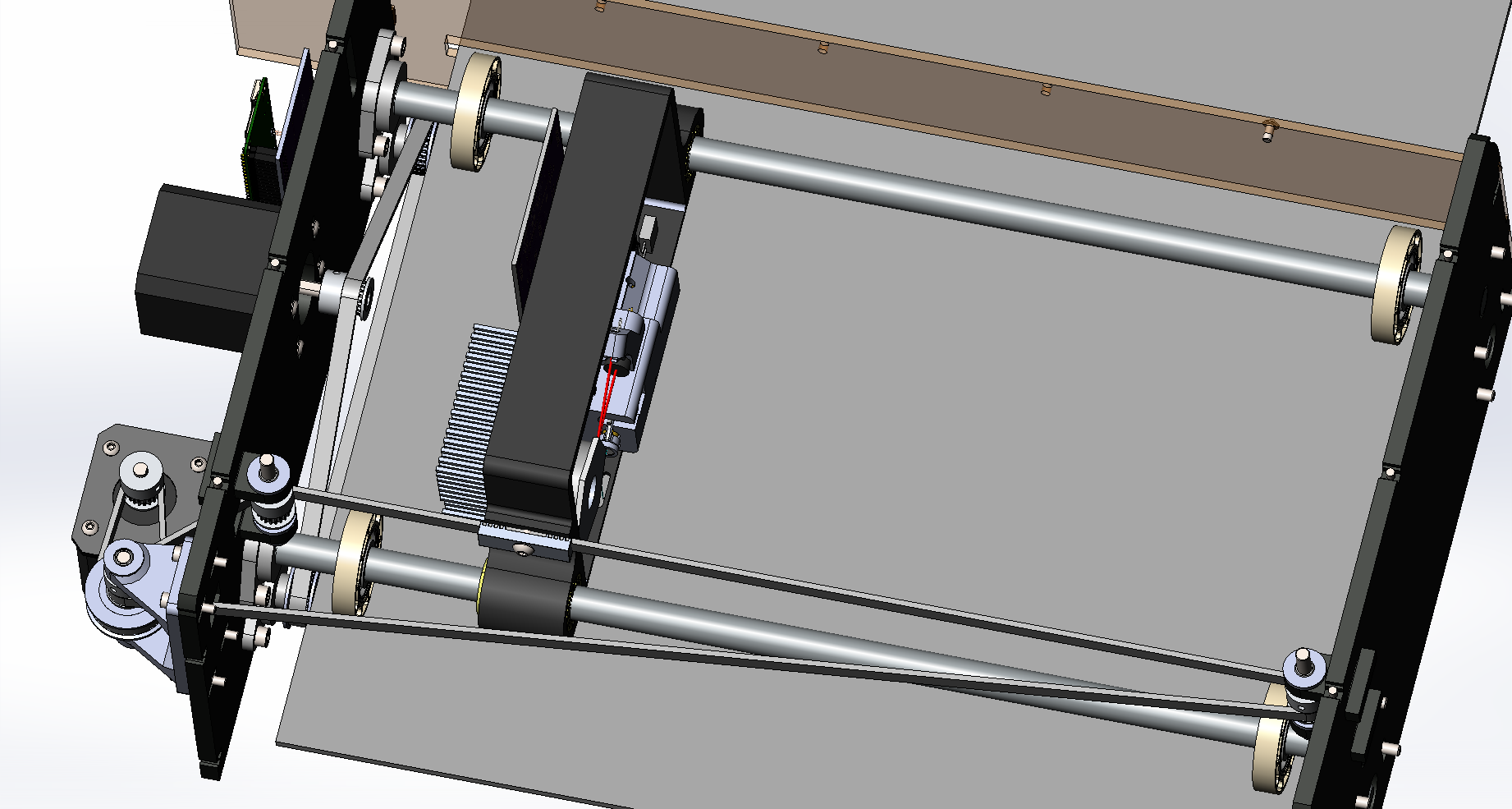
And finally an top view of the head drive system, with gearing and tension take-up bracket on the lower left side;
I still need to do a bit of design work on the end stops and positioning for the head and base plate.
-
looking forward
12/17/2016 at 23:44 • 0 commentsI will hopefully be able to make some progress in the new year, and get a physical prototype built up. I've been iterating through various options for building the laser head with only access to hacksaw, cordless drill and online 3D-printing and laser cutting services (I know some would suggest signing up to open access workshop, but it is just not cost justifiable).
Figure: updated holder block
The most recent iteration makes use of a brass TO-38 laser diode tubular housing, which then allows a fitting piece to couple the collimating lens and bellows tube to the housing. The plan is then to cast a heat sink block using copper powder/fillings and epoxy to couple the brass housing to the TEC module. This avoids the need for custom machining or printing of an aluminium heat sink.
The focusing stepper has also been moved so that it no longer clashes with the trigger laser beam (red).
Figure: Cut-away view showing new internal layout
Figure: TO-38 diode holder off ebay (rough dimensions, needs to be measured)
Looking forward I know that for the current design I am going to have issues with signal propagation and loss of integrity for the high speed switching of the laser, amongst other things.
However at this stage the whole system needs to be run to allow an accurate evaluation of which areas need the most attention, to measure the actual behaviour of the printing chemicals. Which will give a guide to power, pulse duration based on physical data, and allow a comparison with the theoretical calculations. And once I have the hardware, then it is easier to upgrade and test the control electronics.
-
lemon soaked paper napkins
08/29/2016 at 20:44 • 0 commentsWell, my long shot at securing some funds to get this project moved forward to hardware fell through, mildly enthusiastic congratulations to those moving forward to the next round.
To make reference to hitchhikers guide to the galaxy, the odds of intelligent life evolving, proceeding to develop and eventually provide lemon soaked paper napkins following the logic of the probability of something occurring approaches 1 and time approaches infinity.
So may be a while before the physical aspects progress, there will be progress. I will continue to work on the design and coding aspects.
-
Resiliency on UART data - implementing CRC
08/09/2016 at 02:58 • 0 commentsThe communication system between the controller (rPiZero) and print head (Arduino) I decided to simplify the code in the head by using low level functions. These take the hex code strings and pass them directly to the devices or trigger other functions. This allows flexibility and reduces the data that needs to be sent.
I've chosen a standard of 6 byte string with the first byte being the command, then up to four data bytes and finally a CRC byte.
When designing the communication between the head and the raspberry pi, I decided to include a level of error checking on the data passed, as my initial testing showed that signal integrity may be an issue. This has not proven to be a problem thus far. Anyway having a check is good practice. Also the setup process is not a time critical process but one bit wrong could cause problems with setup of the laser diode DACs and thus possible damage to the damage (means I can't blame my typos on interference).
In my research in learning about CRCs I've found the following references useful;
- Cyclic Redundancy Code (CRC) Polynomial Selection For Embedded Networks (Paper)
- Understanding and implementing CRC (Cyclic Redundancy Check) calculation
- Best CRC Polynomials (full data from paper)
The linked paper is interesting as the author has investigated the design space for a huge range of data lengths and code lengths, with the resulting corruption bit length protection. It turns out that the selection of CRC code has a huge impact on the resiliency afforded.
Whilst i'm not gong to try and explain how CRCs work; see the links and your own searches. Essentially there is a balance between the number of bits protected, the number of errors detected and the number of bits in the CRC polynomial.
In my case there is 5x 8bits of data (40bits), i'm using standard 8bit bytes so the CRC can be up to 8bits (may as well use them all). So in my case the 8-bit polynomial 0x83 also known as ATM-8 or CRC-8P is the bet option as it give protection of noticing if up to 4 bits are corrupted and is good for up to 119bits of data length.
If I could send only 7bits easily for the code I would thus use the polynomial 0x5B also known as CRC-7F/4.2 which can protect up to 56bits. This would then save 1bit per transmission/packet which in some situations may be a worth while saving.
---------- more ----------Code - Arduino / C++ (good for both TX & RX)
/*=========================================================================================*/ /* ----------------------CRC ATM-8 check------------------------------*/ /*=========================================================================================*/ uint8_t crcTable[256]; //storage of CRC lookup table void CalulateTable_CRC8() //fill table { uint8_t generator = 0x83; //ATM-8 CRC (8bit) // iterate over all byte values 0- 255 for (int divident = 0; divident < 256; divident++) { uint8_t currByte = divident; //calculate the CRC-8 value for current byte for (uint8_t bitSec = 0; bitSec < 8; bitSec++) { if ((currByte & 0x80) != 0) { currByte <<= 1; currByte ^= generator; } else { currByte <<= 1; } } //store CRC value in lookup table crcTable[divident] = currByte; } return; } uint8_t computeCRC(uint8_t message[], int nBytes) { uint8_t crc = 0x0; for (int b = 0; b < nBytes; ++b) { //XOR in next input byte uint8_t data = message[b] ^ crc; //get current CRC value = remainder crc = crcTable[data]; } return crc; } -
Mechanics progress
08/03/2016 at 19:03 • 0 commentsOver the last month or so i've been mulling over the options for the hardware / mechanics. I've decided to design around off-the-shelf components that I can get off ebay, laser cut flat materials and 3D printed components. As I only have 2ft x 2ft work area (not including the kitchen table) and basic hand tools at my disposal, something that has taken some adjustment.
The two primary rails for the print head are fixed, with four bearings with press fit 'tyres' that ensure that the base-board is the correct distance from the print head. Ive decided to use graphite brass bushings rather than linear bearings as the Chinese ones sound dreadful and i've only been able to source one SKF at a reasonable price so far.
Below them is another pair of rails held by bearings with a degree of adjustment capability to allow take up to the upper wheels. This pair are driven by a pair of 32T GT2 pulleys. The drive rollers will be 3D-printed bobbins with groves for o-rings that will provide grip to drive the base board through the printer.
The paper drive tension is adjusted by the slotted stepper mount and the head translate is tensioned by slotted mounts for the reduction pulley holder.
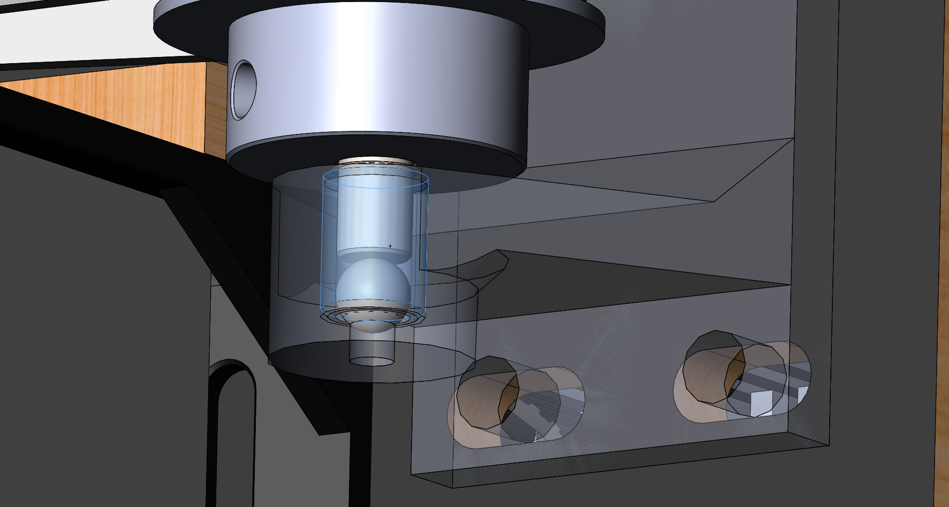
The pulleys are mounted via Teflon coated brass bushings using 3D printed holders with the lower end of the shaft resting on a ball bearing placed within the bore of the bushing; see below.
Bushing mount, bush and ball bearing supporting the shaft end.
The geometry for some of the mounts is not exact and will need updating from the actual components, once in hand.
-
UV laser diode TEC controller
07/29/2016 at 18:41 • 0 commentsI've added a project update for the TEC controller that i'm developing, that's used to control the temperature of the UV laser diode. Firstly to prevent it from burning out and secondly to minimise the power output variation due to temperature changes. Update link
-
Trigger laser angle adjustment
07/27/2016 at 00:32 • 0 commentsSo, having thought through the trigger system i've been working out ways to introduce some capacity for adjustment of the angles, but without affecting the rigidity of the arrangement and relative angles to the UV laser beam.
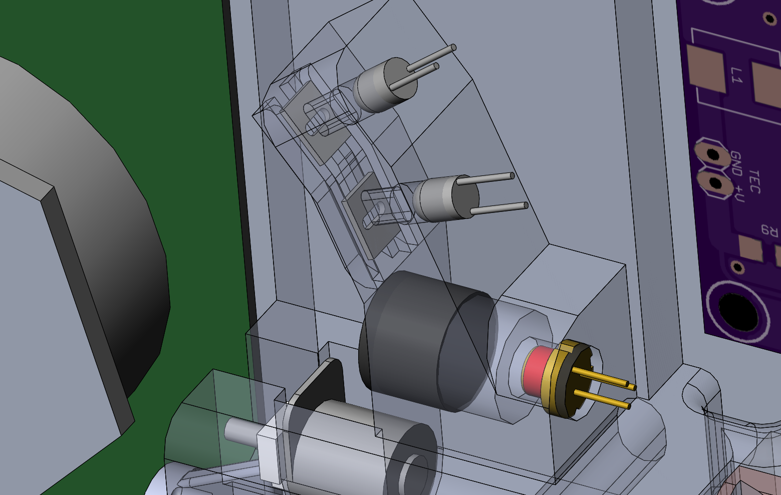
The solution i've come up with is to expand the circular openings into slots, with a slider with perpendicular slot. This allows a small amount of adjustment as the lens of the photo-diode should cope with the off axis beam. There is additional adjustment scope in padding zeros to the beginning of the UV laser data stream.
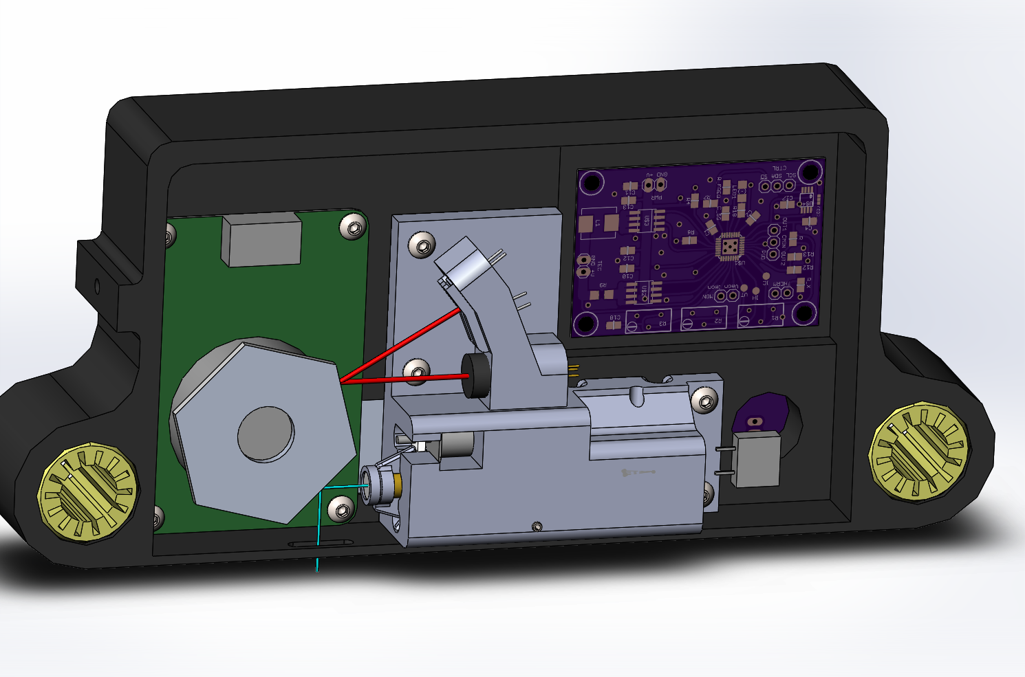
The image below shows the two photo-diodes (on / off via the SR latch) and the trigger laser diode and collimating lens all facing one of the faces of the polygon mirror.
Direct UV Printer for Alternative Photography
Design of a UV printer for making exposures of Alternative Photography prints, direct from a digital image
 David Brown
