 Gorky
Gorky-
1Step 1
Prepare the bed
- Cut a 132x130 mm rectangle from aluminum sheet using your favorite cutting tool.
- Sand one edge (130 mm in length) patient enough to get the outline resemble m3d original bed forming ears that will slide into place just like the original bed. This requires some patience based on your tools and skills but quite easy. Just sand until you have a rectangle as close as possible to original bed in shape and fits tightly into m3d.
- Optional step. Cut another piece 85x85 mm. This piece will be under the big piece mounted as in the image. It provides easier mounting for resistors with screws as it provided more thickness I needed and some heat capacity which may or may not be a good thing. Also sand it a bit so no rough edges.
-
2Step 2
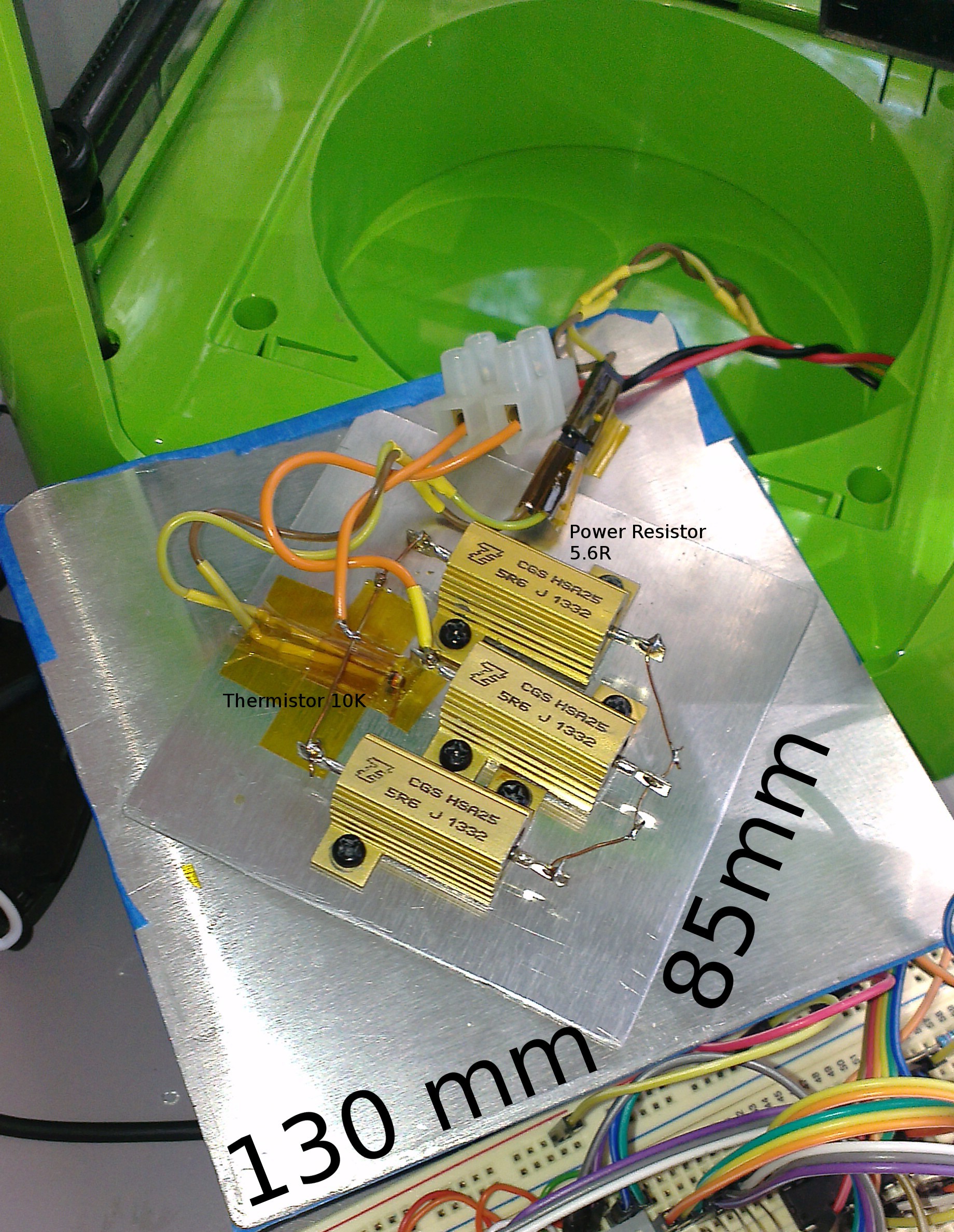
Power Resistors
This pretty much relies on the power supply you choose. I used three 5.6 ohm resistors 2 in parallel and one in series totaling to 8.4 ohm resistance overall on paper. When I divide my supplies voltage 19.5V to 8.4 ohms I get aprox. 2.3A as current which is within limits of the supply and looks like adequate amount of heating power. Also keep an eye on your resistors power rating and try to stay below them. Resistors I used were rated at 25 watts which is more than enough based on this calculation.
-
3Step 3
Mounting resistors and panel
If you have the second 85 mm square sheet cut as well place it in the middle of the bigger cut sheet. You can temporarily use tape to stick them together and make sure they fit into the printer together. If they don't check what prevents a nice fit and adjust smaller sheet position and try until you hit the sweet spot. Don't assemble anything or drill any holes before ensuring the bed will nicely fit into the printer. Once you are happy with the fit and position of the smaller piece draw a border around it and start drilling holes for your resistors. 2 mm deep if you have used 18 gauge sheet. So the idea here is not to drill through both sheets. Use a hobby drill or similar easy to control tool. Also ensure the holes are tight so the screws will hold strong. And be patient. Length of your screws depends on your resistors thickness around mounting holes and plus 2 mm depth of the bed or whatever it is. Not as tricky as it sounds but certainly requires some patience plus trial and error.
Before screwing everything apply a thin layer of heat transfer paste in between everything. Between big and small plate as well as between small plate and resistors.
And at last stick a 10k thermistor with kapton tape keeping a fair distance to resistors. Make sure it's legs are not shorted by aluminum sheet. So use heat shrink or heat resistant insulation to prevent that. I used heat shrink. Highly recommended no issues.
If what you did looks like below, your resistors are tight in place and this whole panel can fit tightly into the printer then hardest part is over.
![]()
-
4Step 4
Drilling M3D and Cabling Stuff
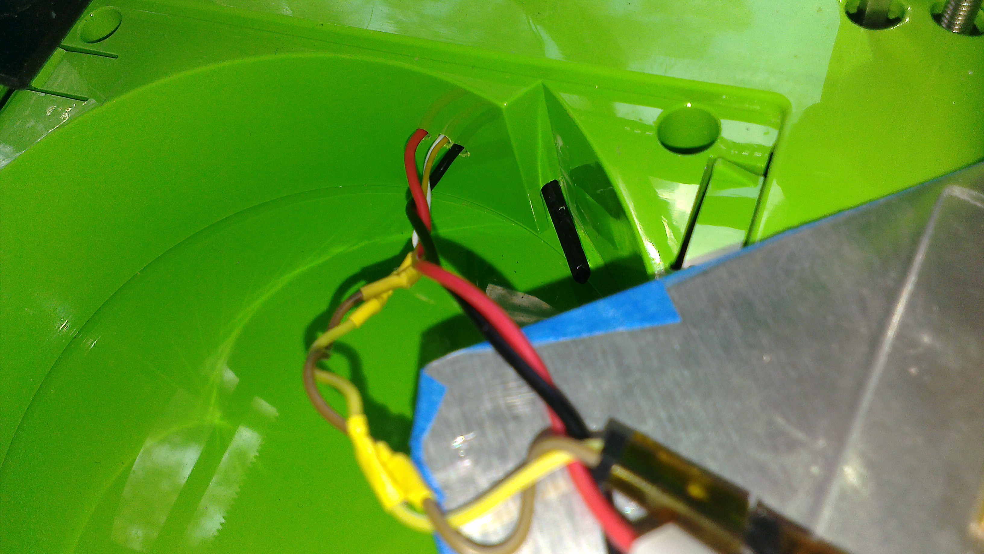
Well this printer of mine had been through terrible experiments so I know whats going inside it. And I decided safest side to drill a couple of holes and drive cables out looks like the right side. So you should end up with 4 cables that needs to go out in total. 2 for power resistor. I would recommend to use something a bit thicker than crappy jumper wires for power resistors as they will carry some amps. And 2 from the thermistor for temperature measurement. Ensure power cables and thermistor cables are not tangled as they might create some unwanted noise in our thermistor lines.
![]()
Holes inside right side
![]()
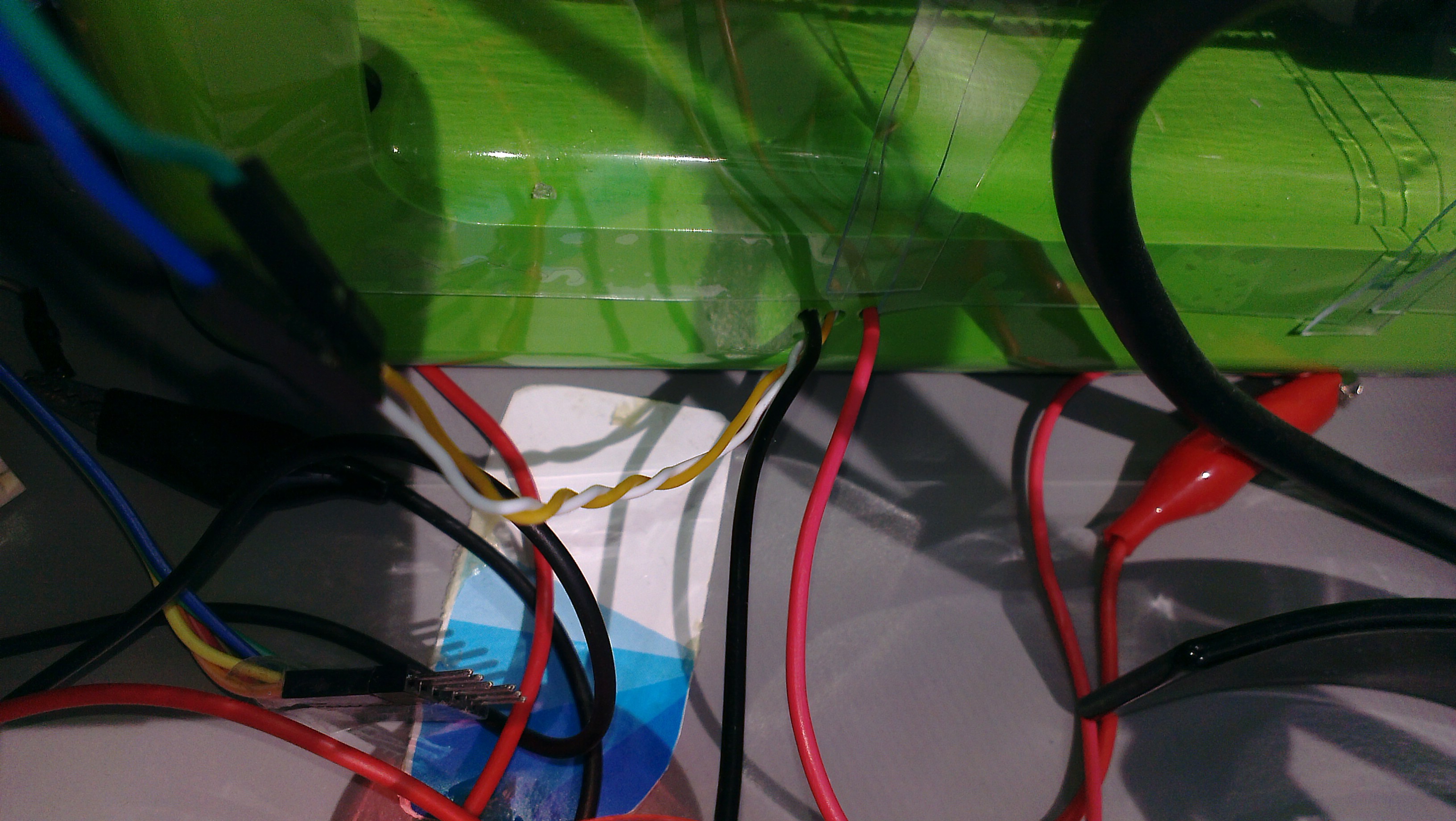
Holes outside right side
Pushing and pulling those cables were a bit painful for me as I wanted to come up with as tiny holes as possible for no apparent reason but quite sure drilling bigger holes will make things easier. -
5Step 5
Controller
If you are done with the above steps you can consider hardest part of this project is complete.
I have used RestIO Model O to control the temperature but you can pretty much use anything which can drive a logic level fet such as an mcu or arduino or esp8266 or whatever your sort of thing is. Or you can get an amazing Rest IO which is one of my projects described here.
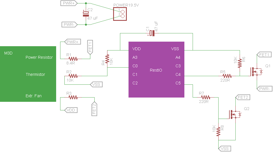
So schematic here
![]()
Port C0 is where thermistor is connected, which is also pulled up with a 10K resistor.
Port C4 controls drives the mosfet. R6 pulls it down so if C4 is floating for some reason mosfet is off. Mosfets are happy as long as there's a decision otherwise they can get hot and unpleasant.
Port C5 is completely optional for driving an extra fan on m3d which you definitely need for reasons I will describe later. But that fan can be always on doesn't need to be that smart. This fan supplied by 5Vs from usb.
C1 and C2 are filtering capacitors and optional. If you plug and play the power supply and don't have those caps RestIO can loose the usb connection temporarily.
Once you're happy with your circuit, connect you power supply, connect RestIO to usb and run the phyton code linked. Check RestIO documentation if you difficulty running it. Or feel free to ask on comments or pm.
-
6Step 6
Extruder Fan and Other Tips
You should consider turning off printers own cooling fan before printing abs. If you are printing a model that is too small and needs the previous layer to solidify quickly you may want to keep the printers fan on but otherwise you should always turn it off.
Before printing from advanced mode heat the extruder to abs temperature and extrude until you are sure that filament is getting out. This step is a must.
Now the printers cooling fan is off and we have a heated bed things will get hot including the filament feeder which is not so good. The feeder will get hot, eat too much into the filament and will lose its pull resulting no extrusion. I solved this issue completely by attaching a small fan like below. That's the fan mentioned in the previous step.
![]()
I ordered a replacement fan from m3d as original one was too noisy. I replaced the fan and fixed, re-purposed the old fan like above.
Blue painters tape is the best choice. I tried to print with kapton a lot of times. It was usually successful but kapton requires very precise calibration and higher temperature which I didn't feel too comfortable with. With blue painters tape, bed heated to 90 degrees Celsius and the fan that's dangling just above the print head I can easily say ABS printing was good. You can switch to PLA any time. No problems. You don't need to heat the bed but heating to 40 will make things less risky. Also calibrate your printer after doing all these things.
Heated Bed for M3D 3d Printer
Usb phyton controlled heated bed for M3D 3d printer, making abs printing possible

Discussions
Become a Hackaday.io Member
Create an account to leave a comment. Already have an account? Log In.
Do your FETs get hot? how are you handling the heat?
Are you sure? yes | no
I dont have much experience in reading electrical circuits. Can you show a connection diagram? I cant see where the thermistors are wired?
Are you sure? yes | no