 mateusz.kolanski
Some time ago I have designed and ordered a few adapter PCBs. Finally they have arrived!
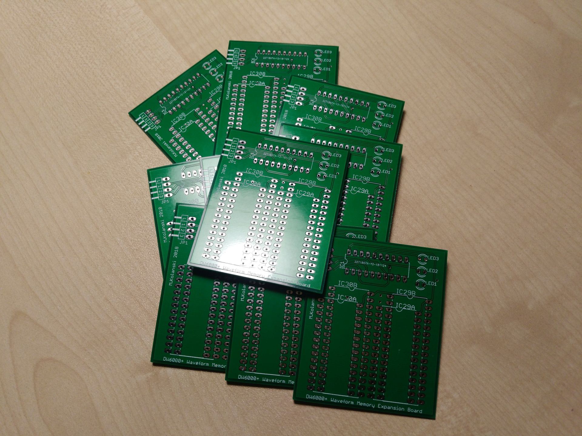
They are looking really good, I just messed up the silkscreen - JP1 should be labeled L321 instead of L123. And the whole PCB is kind of upside down, but I'm really happy how it turned out, not bad for a first PCB:)
This is how it looks after assembly:
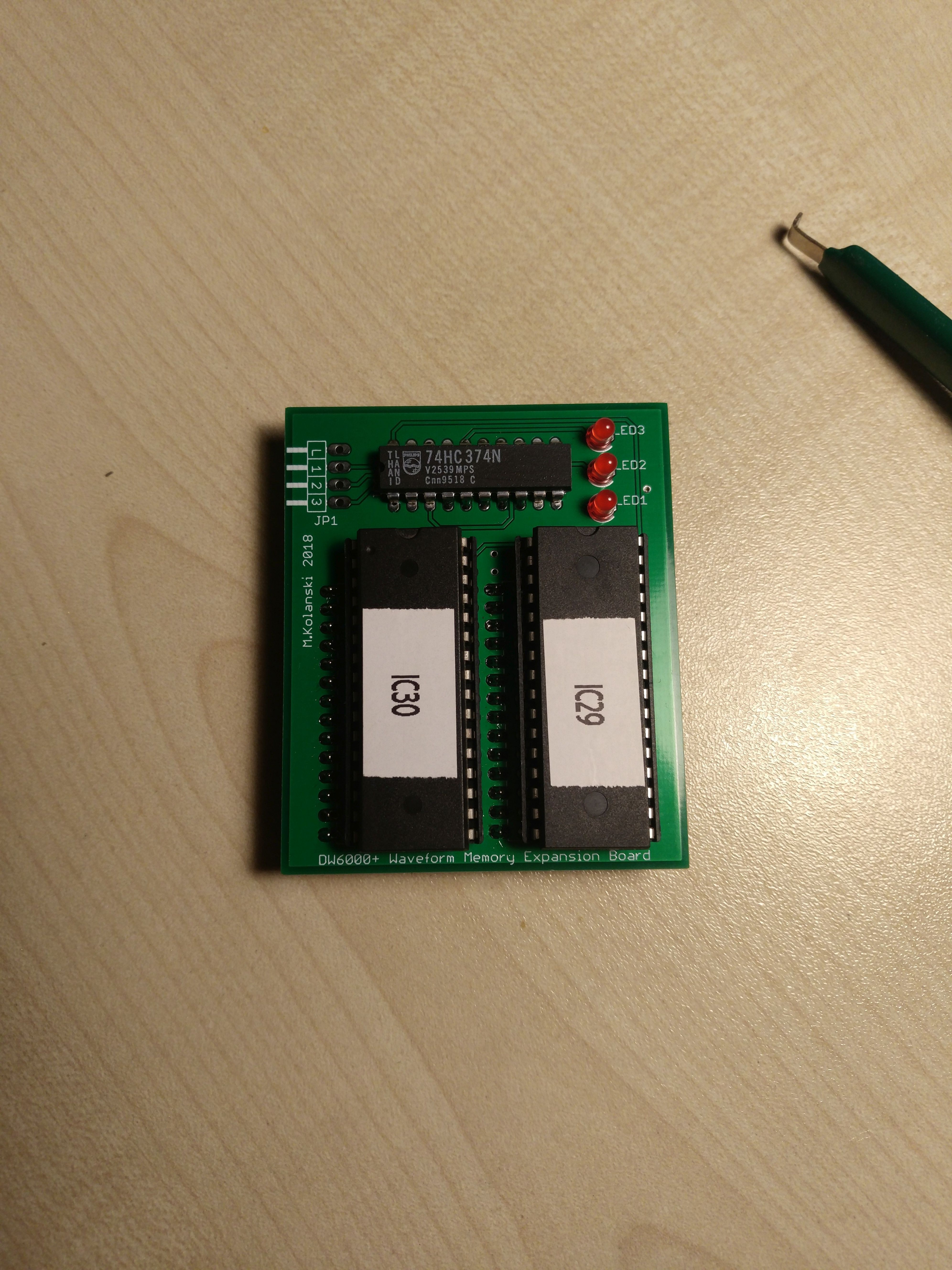
I have decided to put some LEDs (just in case). JP1 is not populated yet, they ran out of angled connectors in my local shop and I didn't want to wait the whole weekend. Fortunately I found an old floppy connector lying around and after some tweaking I got it installed.
Looks nice!
Discussions
Become a Hackaday.io Member
Create an account to leave a comment. Already have an account? Log In.