-
1Step 1
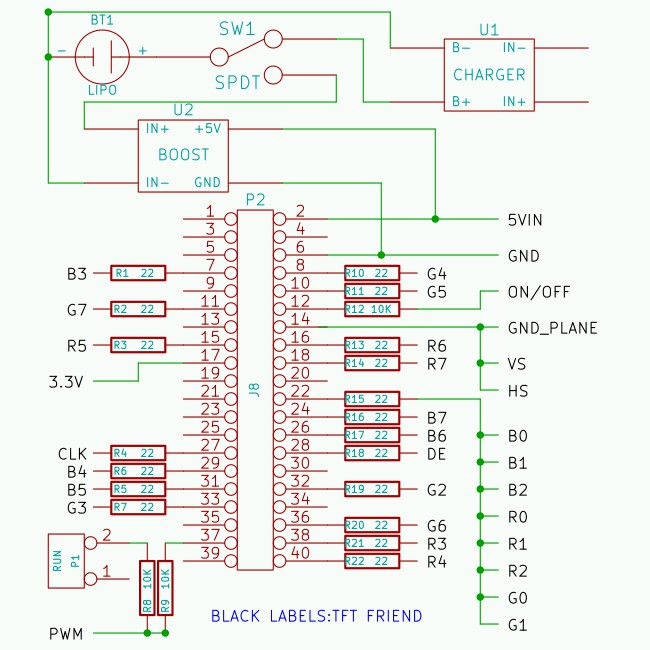
THE SCHEMATIC
![]()
MODS
The Adafruit TFT Friend needs the following modifications: The 3.3V regulator (by 5VIN) must be removed, the 10K resistor next to it must be removed, and the 22 ohm resistor (by CLK) must be shorted out. I also scraped off a bit of the solder mask below the panel connector for a better ground connection.
Most of these modifications are to extend battery life.
WIRING
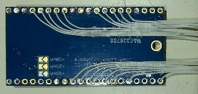
A lot of the wiring on the TFT Friend is done on the back of it. I used 30 gauge wire wrap wire and glued it down with epoxy to ease handling. Mine looks like this:
![]()
For all non-power connections, resistors are soldered to the Zero, then the wires from the TFT Friend are soldered to them. These resistors are important: they series-terminate the high-frequency signal lines. Although not strictly necessary I covered the joints with insulation. I also left the wires long since I plan to experiment with different DPI modes. You should probably trim yours.
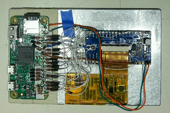
Power connections are made with 24 gauge stranded wire. I used wire from a network cable that had a broken tab. Note the blue ground wire that's soldered to the TFT Friend ground plane. My pile-o-spaghetti looks like this:
![]() Everything is mounted with doube-sided foam tape. The tape under the TFT Friend is trimmed to avoid the wires on the back.
Everything is mounted with doube-sided foam tape. The tape under the TFT Friend is trimmed to avoid the wires on the back.CONFIGURATION
Several files from the files page need to be copied to the Zero: lcd565-overlay goes to /boot/overlays, dt-blob.bin and config.txt go in /boot.
The lcd565 module needs to be put in the proper /lib/modules directory and depmod run while in that directory. A compiled version of the module for the current raspbian is in the files subpage, or you can compile from source. Module compiling isn't that difficult - see these easy instructions


 Everything is mounted with doube-sided foam tape. The tape under the TFT Friend is trimmed to avoid the wires on the back.
Discussions
Become a Hackaday.io Member
Create an account to leave a comment. Already have an account? Log In.