HP (@banjohat)
-
Video demonstration
04/05/2016 at 20:18 • 2 commentsI finally managed to make a short video demonstration of the soldering pen. It can be found here:
I fumble a bit - so much for unscripted one-takes :)
I've tried to compile a list of the things I still need to finish (not in order):
- making a stand
- making a casing
- make temperature control via buttons
- slow down LED pulse
- general cleanup (in HW and FW)I hope you like it (and share the project)
Also - Thanks for the fantastisk StickVise @Alex Rich! I'm sorry I'm using the 3d knockoff. I promise I will get the real one when I order from the HaD shop next time!
-
New PCB revision
03/23/2016 at 20:37 • 0 commentsStatus: Getting really close with that pen-look now!
![]()
Next: Yes, Finally they're here! the new PCBs!
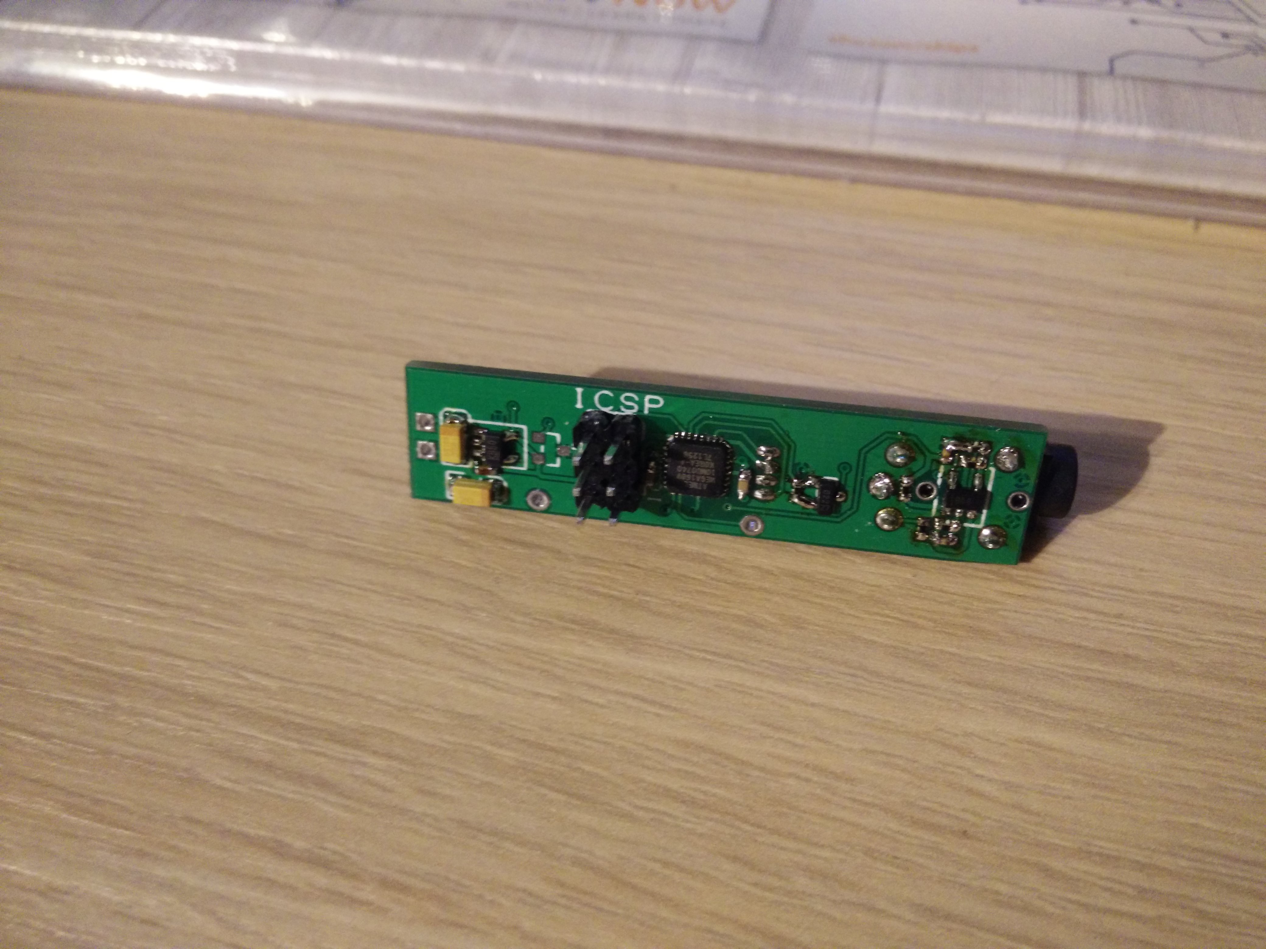
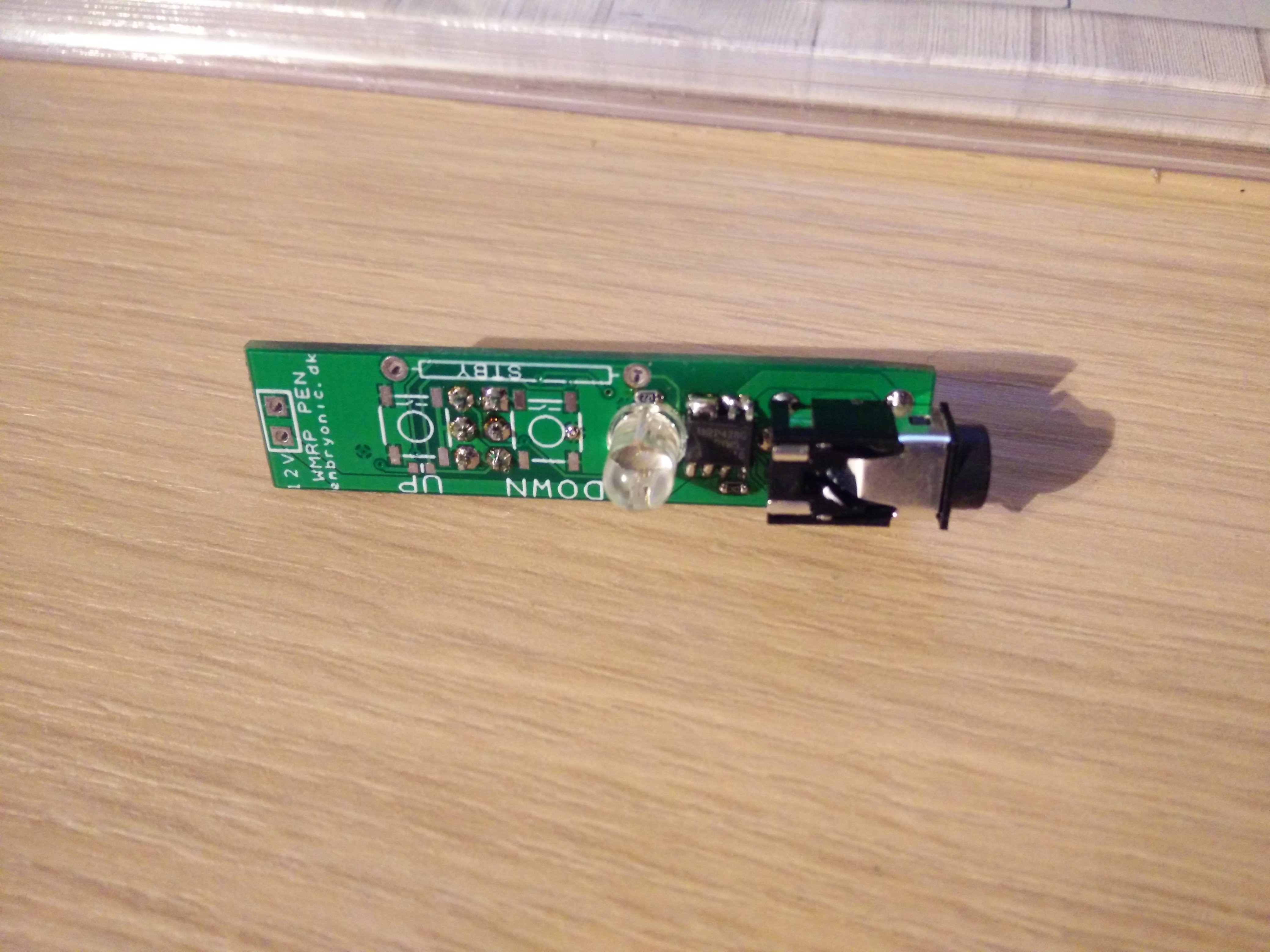
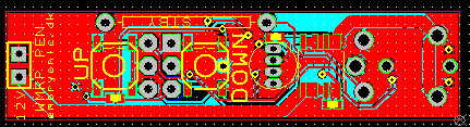
I've ordered 10 from Seeedstudio and after a (not so quick) trip around customs I got them today. The last day before easter. I've panelized them so each board contains 3 pens. that means that after a small bit of sawing I could get to assembling the pieces. Below is a picture of both sides of the circuit.
![]()
![]()
The astute reader will notice that something is missing - the buttons. yes, I don't have any. I've ordered them, but Farnell didn't want to send my package today so that'll have to wait until after easter. that's just how things go.
After the initial ritual with getting confused over where to place components (this thing happens when you do double sided mounting and only have the CAD tool to go from) I had the circuit assembled.
After frying a tip on the prototype earlier I decided to go slow and set a temperature of 30 degrees. Without plugging the pen to 12V I heated the tip with my other soldering iron and was looking for the heating indicator (Red on the RGB LED) to go out. after a few very long seconds it went out! yes, it's working!
I adjusted the power for 50 degrees and put the power on. the real power. the power power. 12V. seconds stretched very long but indeed the heating indicator went off and startet blinking very slowly. the system was now keeping the tip at 50 degrees! yes! double and triple yes!
Last test for now was adjusting the temperature to 350 degrees. power back on and wait.. smoke from the tip - oh no - and then, heating indicator off again. phew! now we're talking!
The hardware is almost finished with only the hall sensor / reed relay missing from the PCB. it should be quite easy to add later on when the firmware's ready.
-
Soldering station – Now without the station
03/15/2016 at 08:04 • 0 commentsI’ll start with a picture.
![IMG_20160314_195219]()
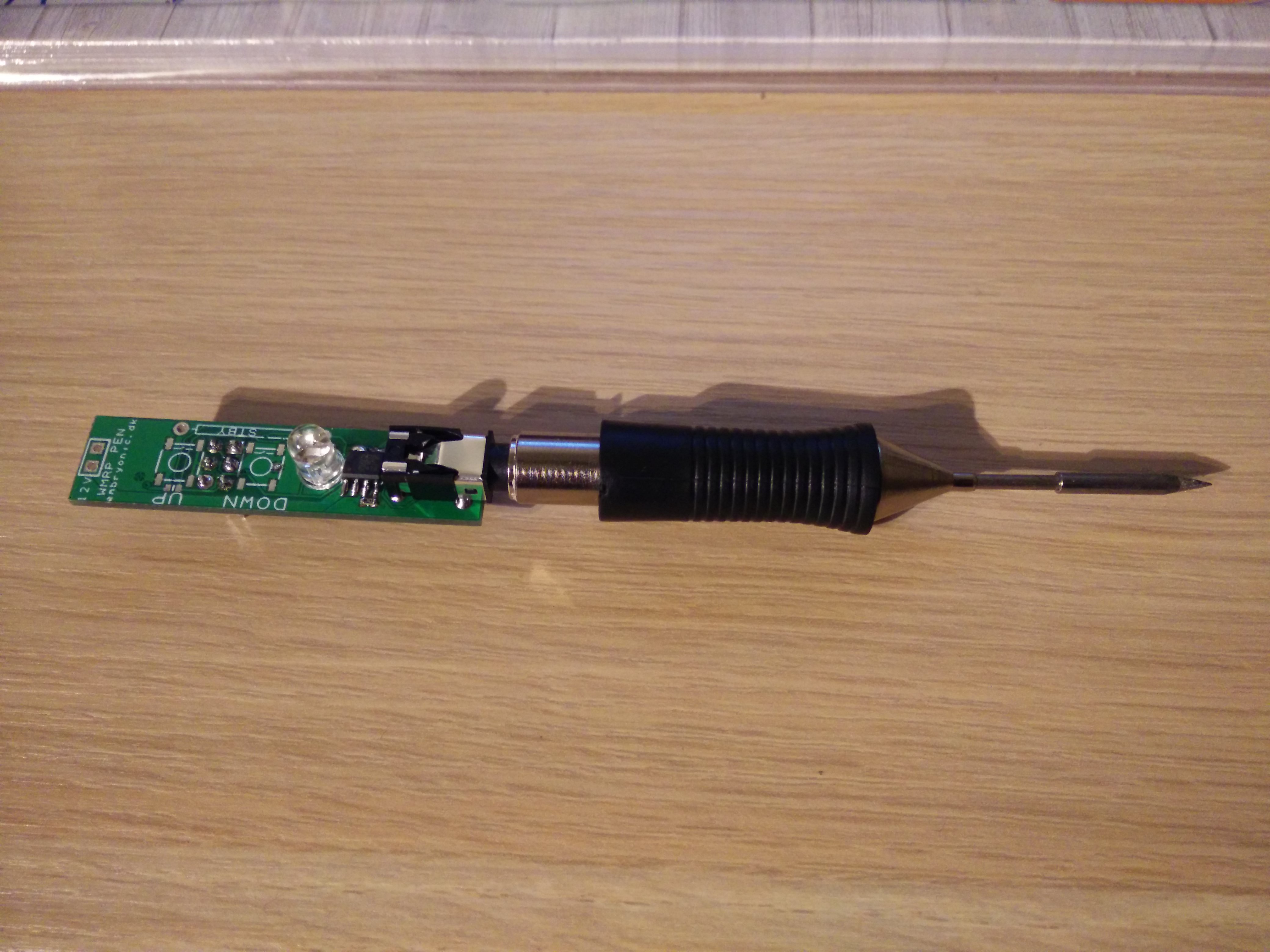
this is the mini soldering station I have started working on. What you can see is the RT tip directly attached to the controller board. the idea is of course to have a mini-jack extension cable in between, but then it hit me. why?
Why don’t I just make the whole system small enough to fit into the same width as the tip? If I let go of the USB connection and instead add a button or two all I need is a method of indicating the temperature. Back to the drawing board.
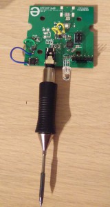
![solderpen]()
Now we’re talking!
the PCB is 12 mm wide and 50 mm long. I have been a bit creative with component sizes and placement. but it fits, even with room to spare.
Also I have solved the issue with temperature indication. The system will still store the selected temperature in EEPROM. when adjusting the red LED will blink one time for each hundred degrees (300 degrees = 3 blinks) and the Blue one time for each 10 degrees. I dont want to adjust for single degrees but other users will easily be able to adapt the firmware if they want to.
Hardware changes from the first ‘station’ version: No FTDI header – only ICSP programming. also, No resonator. I don’t need serial communications so I don’t need precise timing. away goes the crystal and caps.
I’ve added a footprint for both a reed relay and a hall-effect sensor. the reed relay was my first idea but after some input I decided to put on a hall sensor. It’s also mounted at the bottom side and centered so this will likely be a much better location than the reed switch which is located on the topside to the right.Again, the waiting game is played. waiting for PCBs… I will get started on a 3d printed casing while I wait.
This entry was posted in Soldering Station by hp. Bookmark the permalink. -
The chicken or the egg
03/14/2016 at 19:00 • 0 commentsSo which came first?
I have a tray with ATMEGA168's. the only problem is that the package - MLF. In other words, No leads and damn small. Lucky I have tried soldering fine-pitch no-lead packages before, but this is getting ridiculous. how will I solder my new soldering station? with the very tip that I'm building a station for. It's like brain surgery on yourself.
Luckily I have access to a real Weller station at work so during my lunchbreak I quickly soldered a MCu to one of my PCBs. Back home I could then put on headers and 'big' components, like 0603 resistors and caps.
First light
It's always interesting when a new board is powered on the first time. Will it let out the magic smoke? will it just don't work? Even though I have done plenty of projects I'm still not sure what to expect at the first power-on. could it be THAT time when it just explodes in your face without warning?
Hesitantly I turned on the power and .... nothing. well. phew, no smoke, no explosion, not today at least.
I put on the ICSP header just to find that I have put it on mirrored. Damn. Made a new adapter and uploaded a blink sketch. yay! light! MCu is working along with Oscillator and the LED. so far so good.
Too much light
The next thing was the analog front-end. This is the part where I have been using the design from Martin Kumm. I actually tried to write him a long time ago and ask permission but he never replied. I guess that the open source still applies when his work is still online with the license text so I soldered up the Op-amp.
again, nothing. After a quick inspection I found that the opamp had the inputs switched. Damn damn.
cut traces and add wires. signal? Check!. Okay, now I could sense the temperature of the tip, reading a stable 25/26 degrees. I took my still hot soldering iron and touched the ned RT tip. the temperature was rising! fast! fantastis, that meant that the sensor was giving me readings. that would work.
next up was the power output: PMOS with an NMOS to provide the right signal type. The big moment - power on with the tip.
and BAM. disaster. In what turned out to be a reverse PMOS (I really screwed up with mirroring this time huh?) The body diode of the beefy FET was providing a clean path through the RT tip and before I could do anything the tip was glowing an eerie red. I turned the system off as fast as I could but the damage was done. the heating element of the tip was destroyed. resistance read 390ohms. Dang.
Soldering pen
Cheaper fine-pitch soldering setup with Wellers RT tips