Mike Rigsby
-
Mounting 9000 Farads
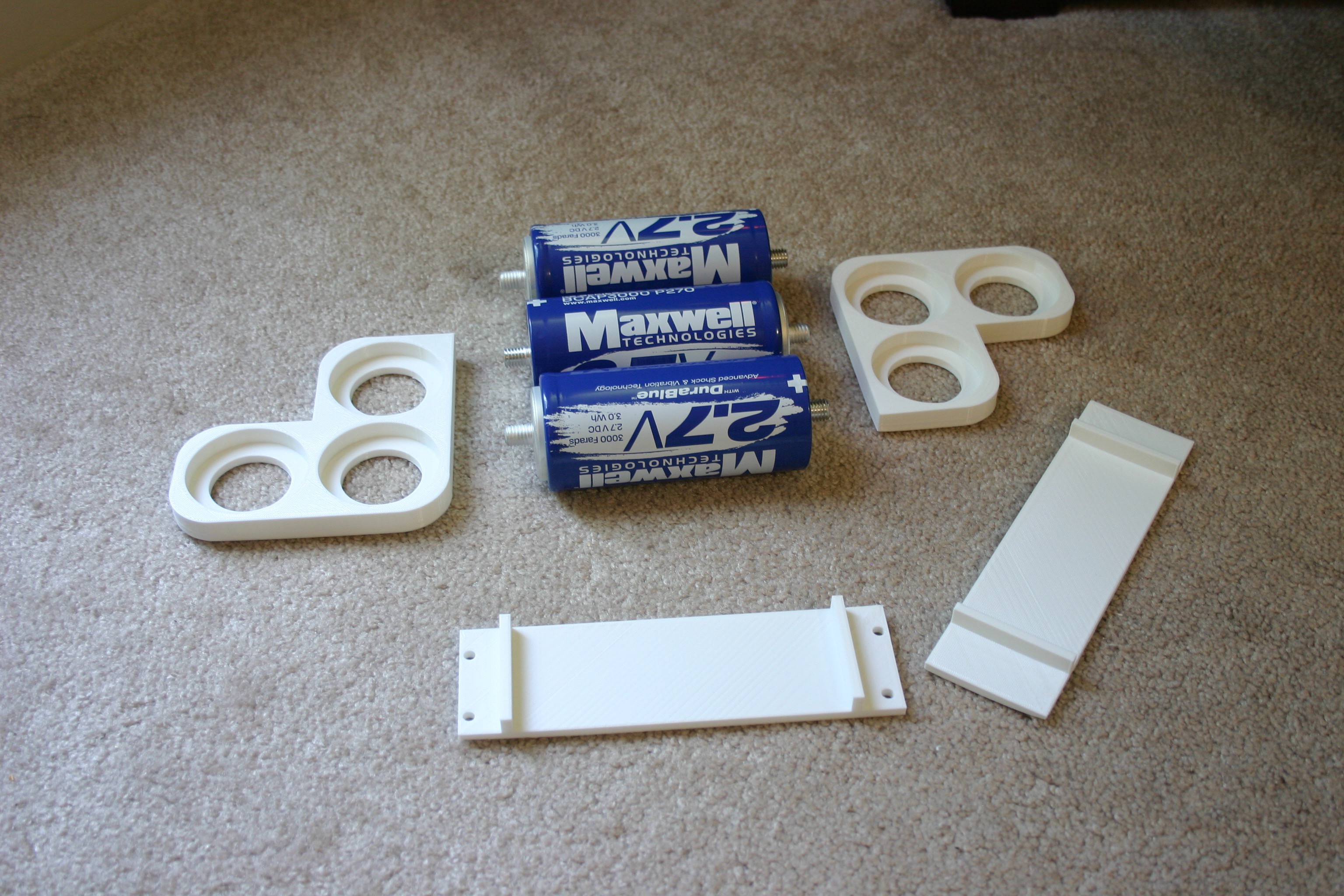
06/21/2016 at 18:20 • 0 commentsThe time has come to mount (3) 3000 farad capacitors on Little Friend. The idea is to set them up in series, so the end result will be 1000 farads at 8.1 volts. I had to design and 3d print some brackets (files included in this project).
![]()
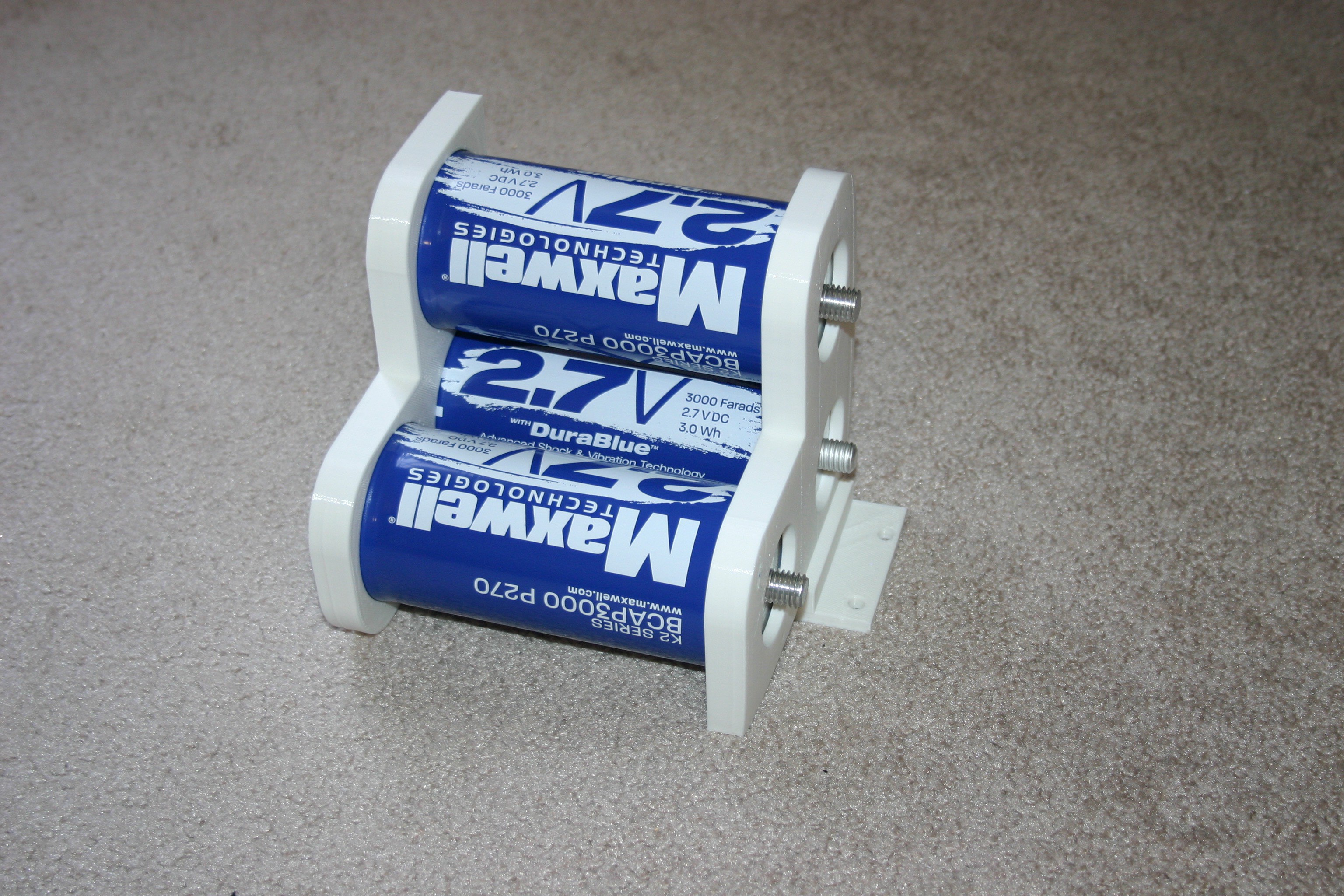
I placed the capacitors into the end pieces and glued (melted) the bottom bracket to the end pieces.
![]()
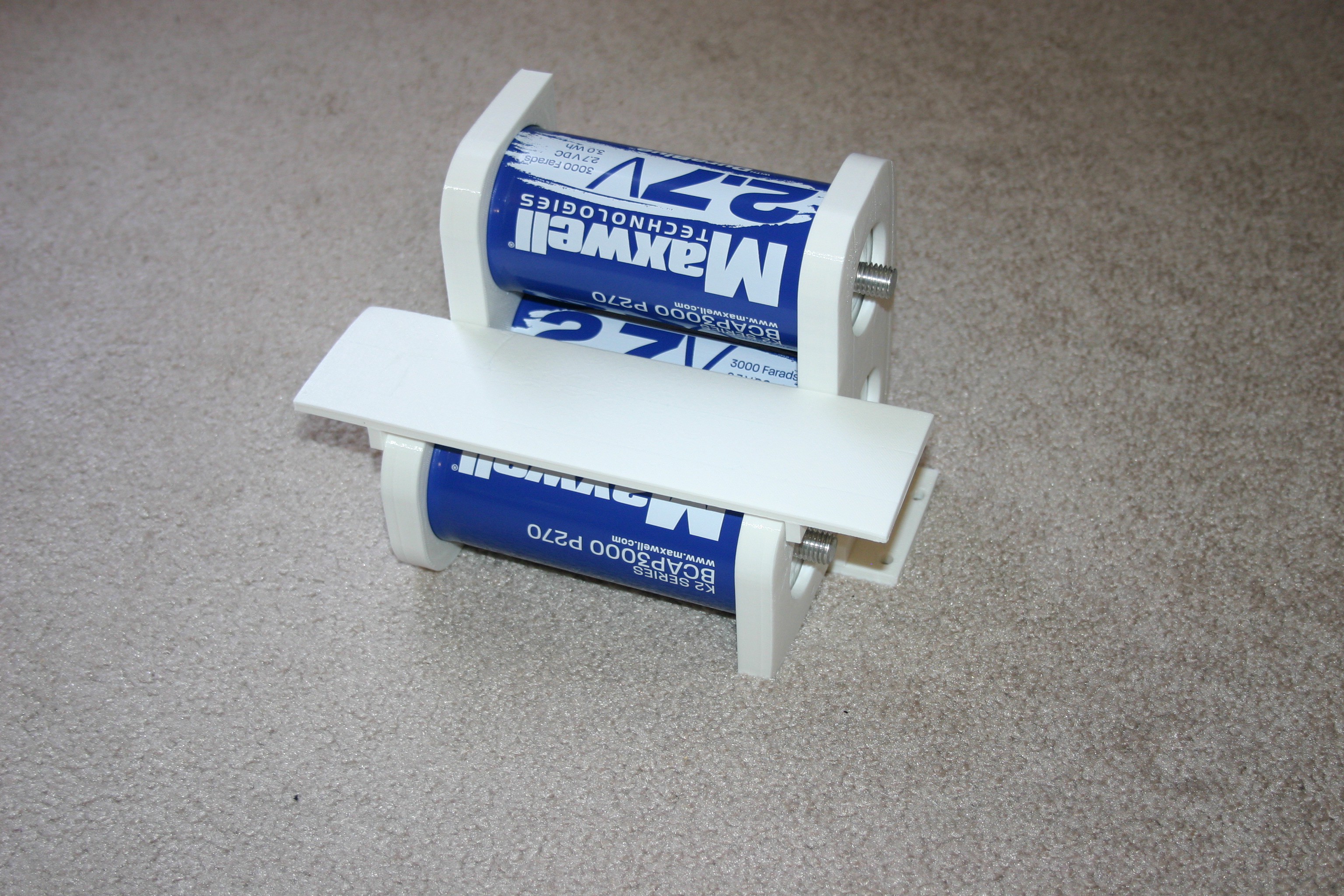
Next, I melted the top bracket (which will be an electronic shelf) onto the end pieces.
![]()
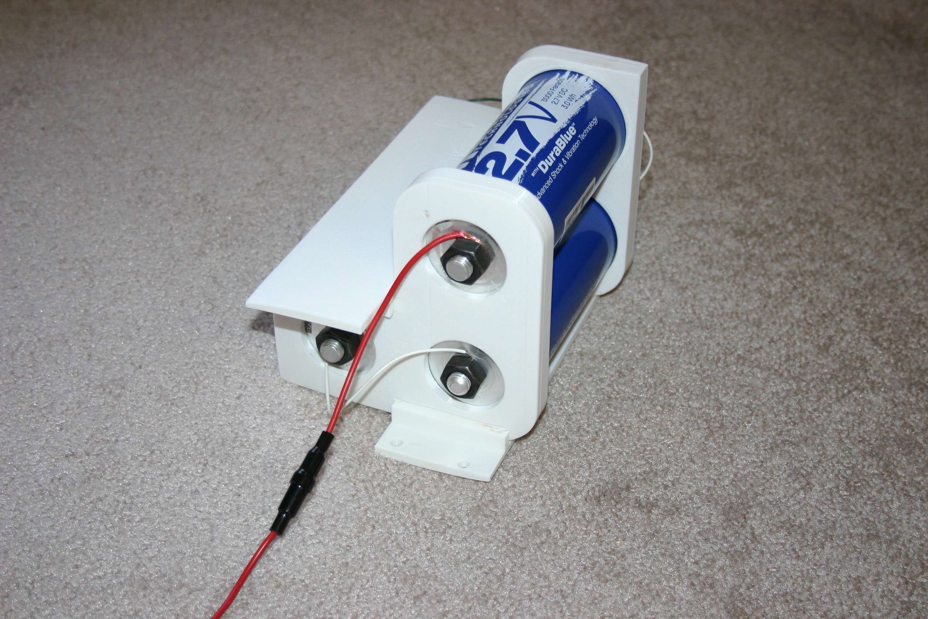
Next, I added a 10 amp fuse and size 22 connector wire between the capacitors. The connector studs are so large (about 1/2 inch diameter), that I couldn't find any connectors for my small gauge wire. I stripped an inch or so of wire, wrapped it around the stud, and fastened a nut to the capacitor.
![]()
At this point, I thought I was ready to put some charge on the capacitors. Note to myself, there is a WRONG way to assemble an inline fuse.
![]()
Being cautious, I set my power supply on 3 amps and started charging. After a couple of minutes, the power supply quit producing amps and a terrible burning smell was coming from somewhere.
![]()
Everyone reading this thinks "What a dufus!", but I now know that the spring goes behind the little brass stud. It's spring, stud, fuse, stud.
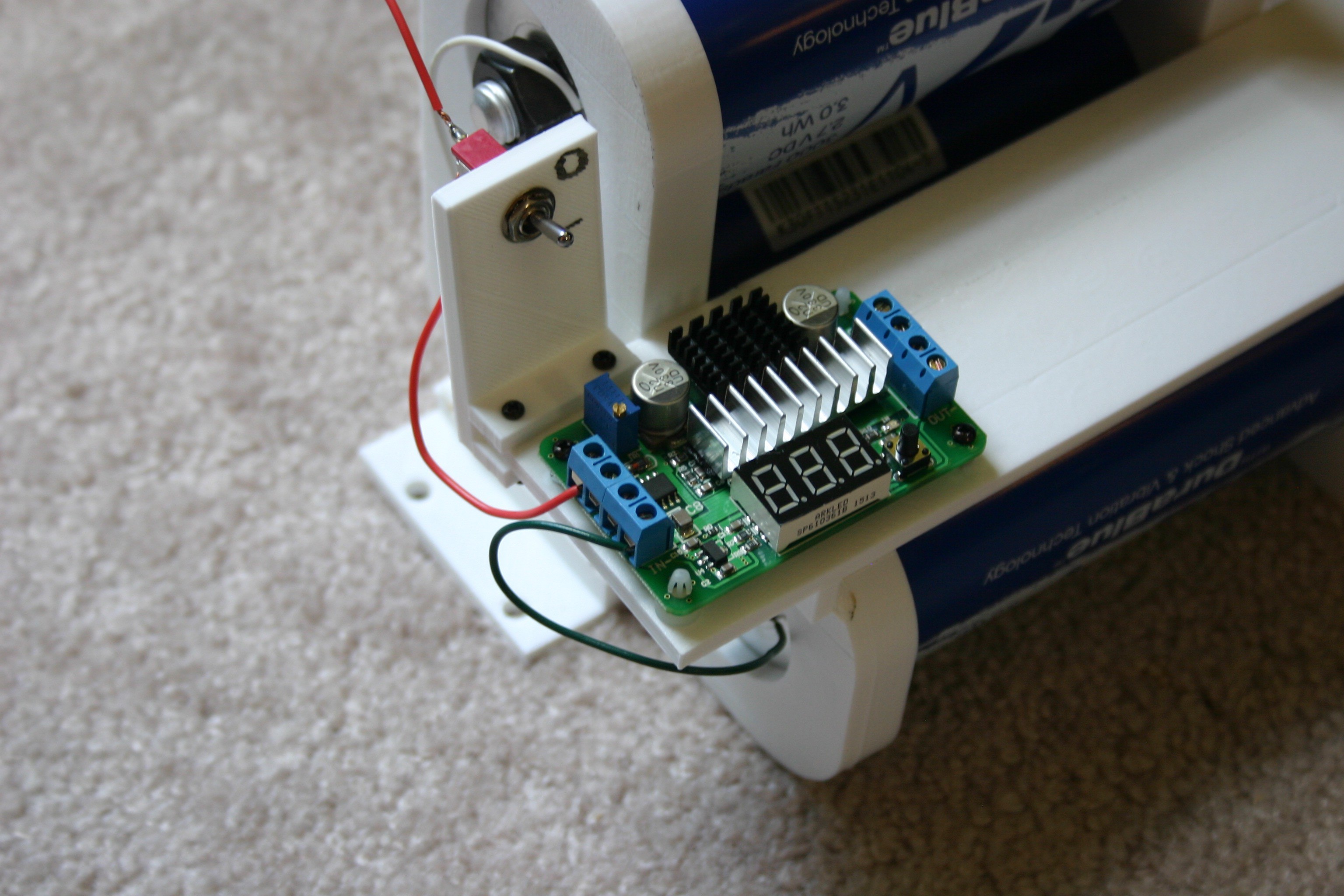
This rattled me a bit, so I decided to install my on/off switch and dc boost converter before trying to charge. First comes the on/off switch.
![]()
Next comes the boost converter.
![]()
Then, bring wires into the boost converter.
![]()
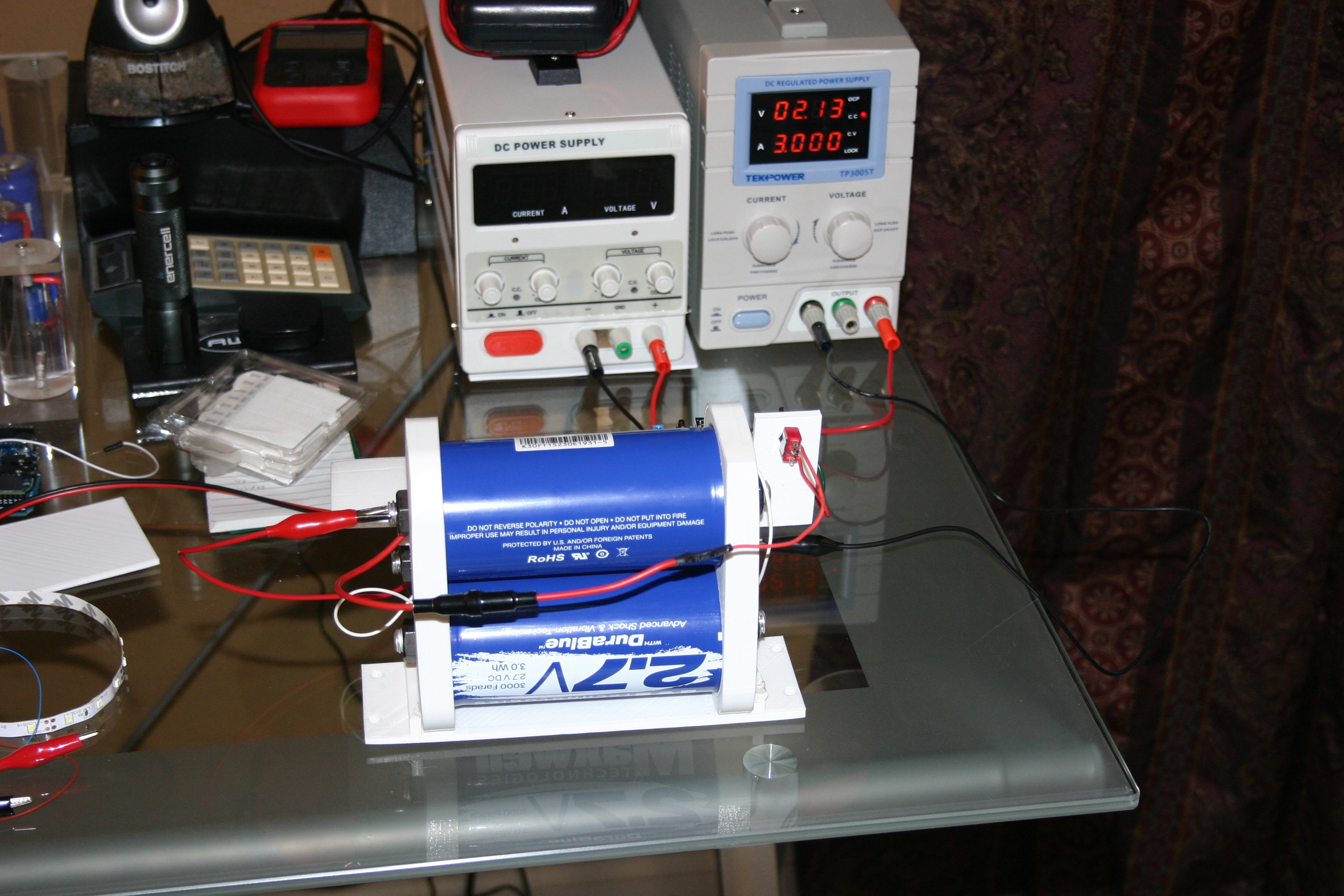
Now, I restart the capacitor charging process. I didn't want to go crazy, so I set the power supply at three amps and let it work to bring the capacitor from zero to about 6.5 volts.
![]()
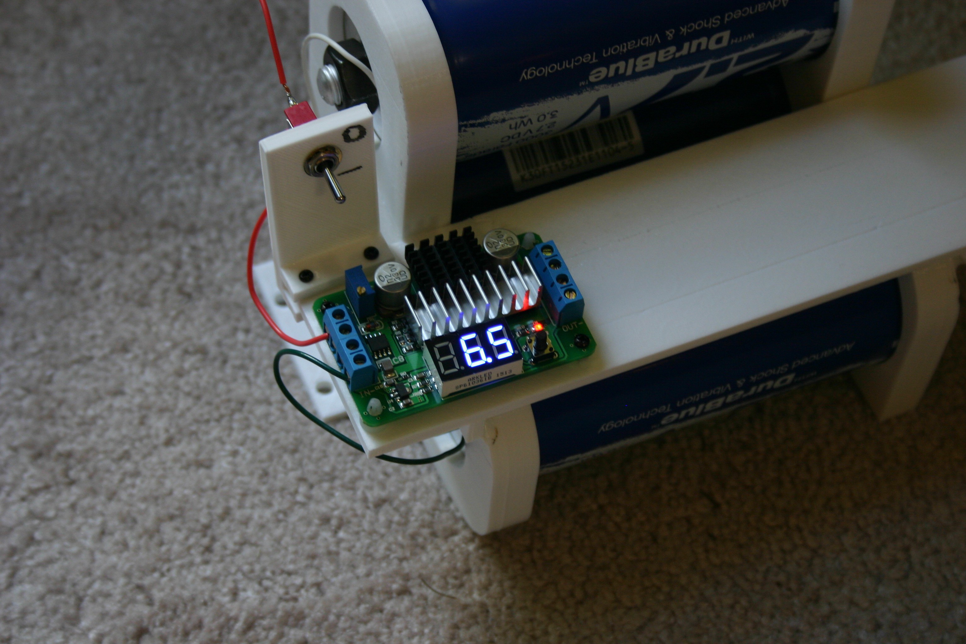
This took about 25 minutes. Rather than going up to 8 volts, I was anxious to see results, so I turned on the switch and looked at the input voltage to the boost converter.
![]()
I connected Mato's two gear motors (spinning freely in the air--she's not all assembled with her new supply yet) and measured a current drain of 53 mA at 11 volts (the output of the boost converter). After 60 minutes in this configuration, the capacitor voltage was 6.0 volts. I spot checked the components on the boost converter, but never detected any temperature rise.
-
Ultracapacitor or Battery?
06/14/2016 at 17:26 • 1 commentIf you are a hacker, interested in doing things differently, here's some basic information regarding ultracapacitors.
![]()
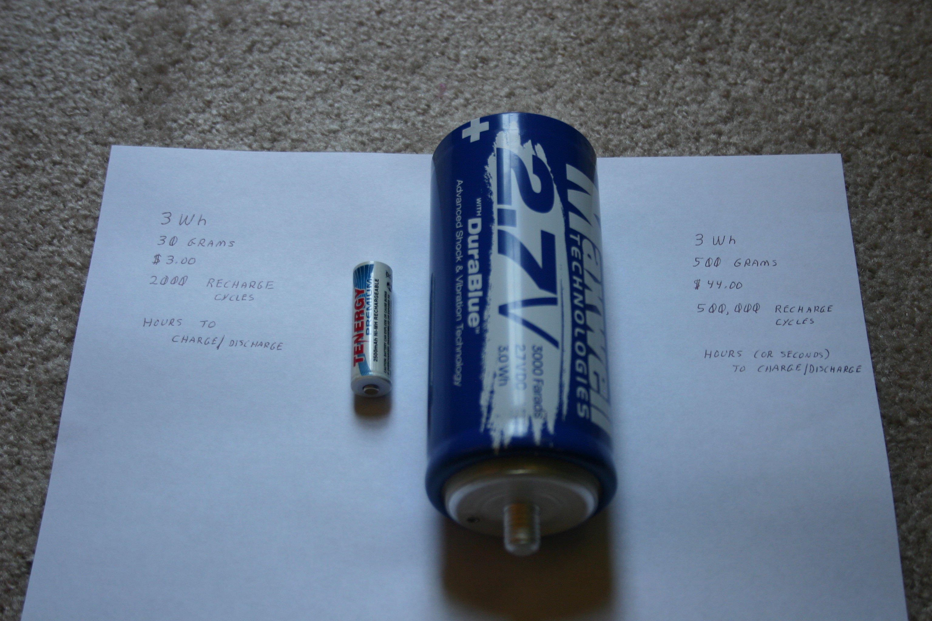
For a fast "rule of thumb" comparison, 1000 farads at 2.7 volts amounts to about one watt hour of energy storage. This means the 3000 farad capacitor above stores about the same energy as the NiMh AA cell pictured above. Using a La Crosse BC-700 charger, I charged the AA cell above (rated at 2500 mAh) at 500 mA--discharged at 250 mA--and recorded a capacity of 2330 mAh. The capacity and number of charge/discharge cycles of batteries depends on battery chemistry and charge/discharge rates.
I took five 350 farad capacitors (in series) and charged them to 12.72 volts. After 24 hours (no load attached), the voltage had declined to 12.57 volts. After 48 hours, the reading was 12.50 volts. Capacitors will lose noticeable charge in a matter of days.
A 30 gram battery (NiMh) is comparable to a 500 gram capacitor. Clearly, batteries are the winners in this category.
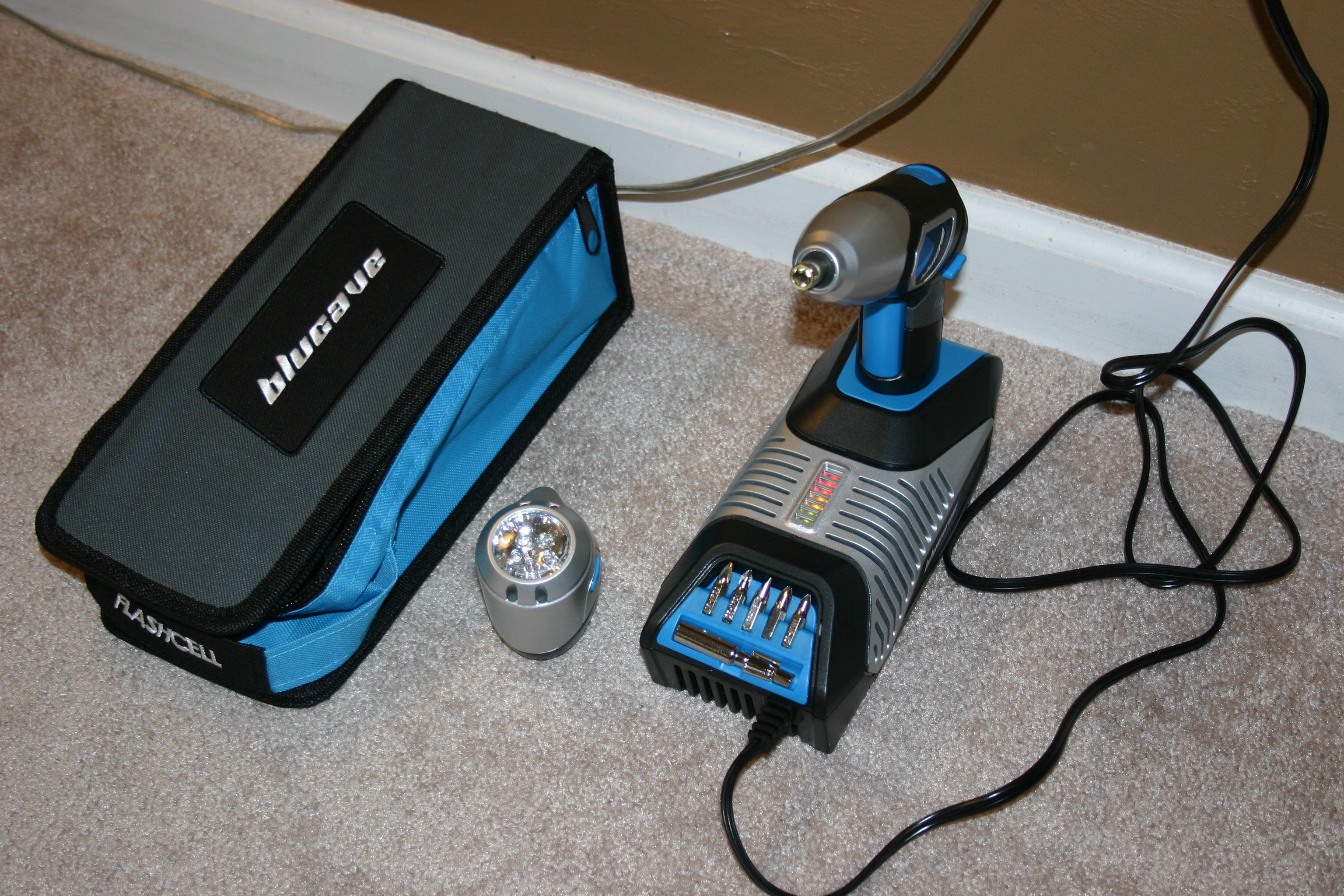
Cost--here's an interesting area. First, a little history. In 2009 I purchased twelve 350 farad capacitors and they cost $23.00 each at the time. Today, the same capacitors from the same company (tecategroup.com) cost $10.75 each in quantities of ten or more. So, the cost is coming down. Using our comparison above, a $3.00 battery can be good for 2000 charge cycles--the $44.00 capacitor is good for 500,000 charge cycles. If you had a need to charge/discharge 500,000 times, you would need 250 batteries to accomplish the task ($750. versus $44.00). So, are there any consumer products utilizing ultracapacitors?
![]()
Yes--this screwdriver/flashlight charges in 60 seconds and is currently available on Amazon.com for about $21.00. This appears to be a product that was launched for $60. and didn't make it, so don't expect it to be around forever. Coleman made a capacitor powered screwdriver a few years ago (I owned one), but I can't speak to it's long term functionality as I tore it apart for all the good pieces it contained.
Unlike batteries, the voltage steadily declines on a capacitor; meaning that more circuitry is required to keep the output usable.
Ultracapacitor sales do not target hackers or consumers--they are intended for rail systems, trains, utility vehicles; that sort of device. Look at the "bolt" connectors in the top picture. The M12-1.75 bolt is about one half inch in diameter. We're not talking about 300 mA discharge and 10 amp charge rates. These things are designed to move serious amps in a hurry.
That being said, if (like Mato) your goal is to charge quickly and get back into service (hand tools, flash photography, robots, toy vehicles) capacitors deserve a look.
When my 9000 farads (really 1000 farads at 8.1 volts) are operational, I'll provide more information on charging and discharging in the real world.
-
9000 Farads for Mato
06/13/2016 at 18:54 • 0 commentsMato, with 1750 farads, could run for more than 15 minutes of continuous movement--eyes blinking and such.
Today, the UPS person delivered a new energy source; three 3000 farad capacitors.
![]()
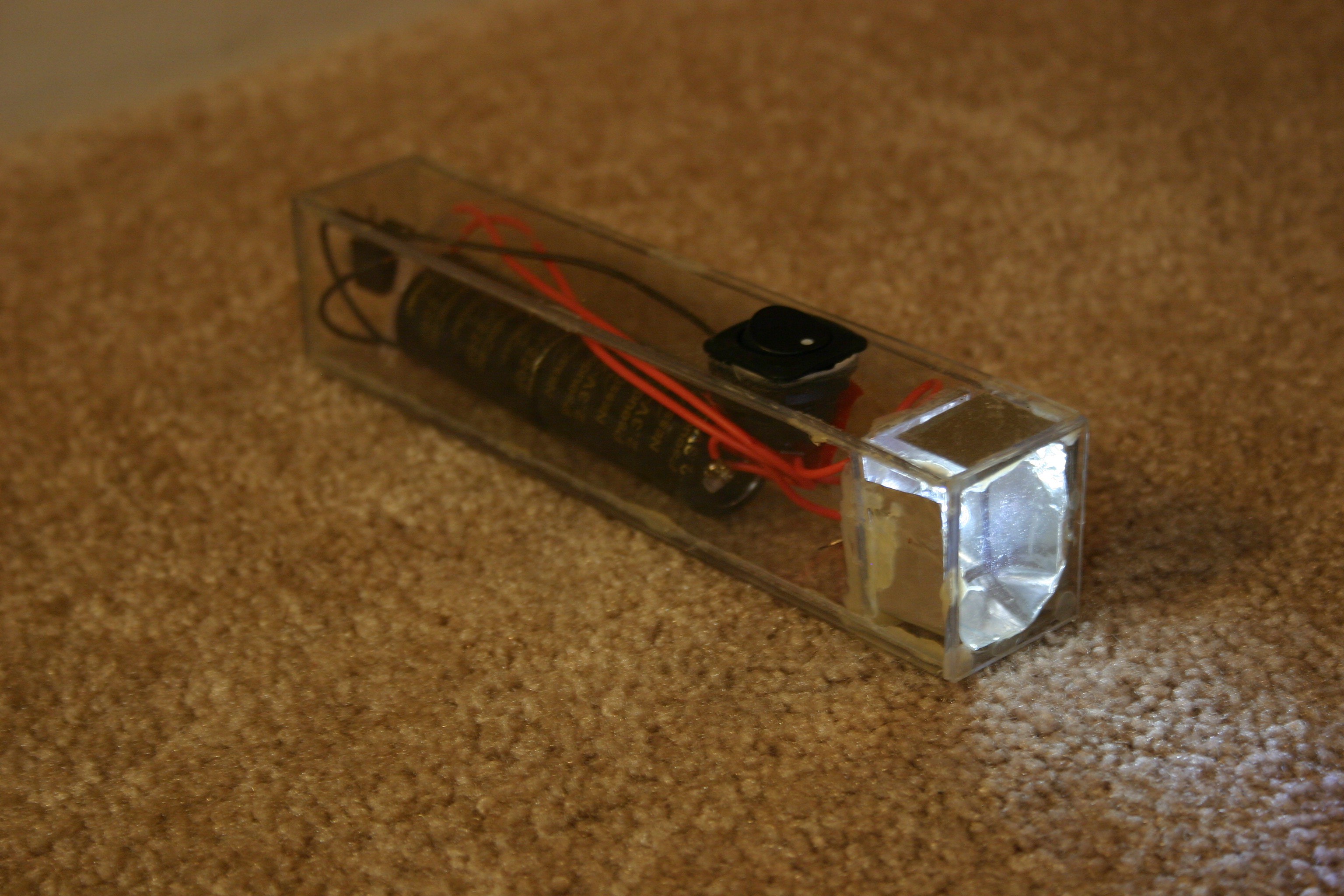
I'm going to put on my "Citizen Scientist" hat to measure and analyze the pros and cons of capacitors versus batteries. I've used these before, starting in 2009 when I built and documented a flashlight. This still operates today.
![]()
Getting a bit bolder, I took twelve 350 farad capacitors and combined them with a hand crank generator to make a human powered desk light. I've been using these capacitors since 2009 (I had the hand crank generator, an inverter, the capacitors and a light at the 2009 San Mateo Maker Faire--I also did a presentation on ultracaps). This light is in my workroom and I crank it for three minutes or so every day (trying to keep my arms from turning to pure flab).
![]()
Think of a phone or pad that charges in 60 seconds instead of hours. We're not there . . . yet.
-
Recognizing Speech with MOVI shield
05/28/2016 at 23:10 • 0 commentsThis is my first test of MOVI, the speech recognizer and synthesizer. It is very easy to set up and use.
The shield works with Arduino and can be found here.
I changed one of the sample programs so that the shield would recognize "Mato" when spoken. In a quiet room, I had success at a distance of over 30 feet from the recognizer board.
Here's the pertinent part of the code:
recognizer.init(); // Initialize MOVI (waits for it to boot)
//*
// Note: training can only be performed in setup().
// The training functions are "lazy" and only do something if there are changes.
// They can be commented out to save memory and startup time once training has been performed.
recognizer.callSign("Mato"); // Train callsign Mato (may take 20 seconds)
recognizer.addSentence("Let there be light"); // Add sentence 1
recognizer.addSentence("Go dark"); // Add sentence 2
recognizer.train(); // Train (may take 20seconds)
//*/
// recognizer.setThreshold(5); // uncomment and set to a higher value (valid range 2-95) if you have a problems due to a noisy environment.
}
void loop() // run over and over
{
signed int res=recognizer.poll(); // Get result from MOVI, 0 denotes nothing happened, negative values denote events (see docs)
if (res==1) { // Sentence 1.
digitalWrite(led, HIGH); // Turn on LED
recognizer.say("and there was light!"); // Speak a sentence
}
if (res==2) { // Sentence 2
digitalWrite(led, LOW); // Turn off LED
}As you can see, it's not too difficult to program the recognizer.
The downsides:
The power cannot be supplied by usb--it must be a higher external voltage (like 7 volts or so). Current consumption (in my test) was about 140 milliamps for the Arduino and shield while waiting for speech. Recognition time is a couple of seconds.
Will this "hear" over the sound of motors while moving? I don't know. This is one of the "feature creep" items I mentioned at the start of this project and I will delay any serious implementation until the "find my recharge station" capability is operational.
Mato is excited about the possibility of being able to hear and speak!
![]()
-
More About the "Connor Nishijima Effect"
05/26/2016 at 21:06 • 2 commentsI've been working on this "human detector" sensor and I have more information to share. First, I wound (two) four inch long insulated wires around each other (not electrically connected). One goes to pin A0 of an Arduino Uno, the other to ground.
![]()
While playing around with software, I noticed that I could only get predictable results when my delay between two readings was an exact multiple of 16.7 milliseconds--something to do with 60 cycle (powerline) frequency.
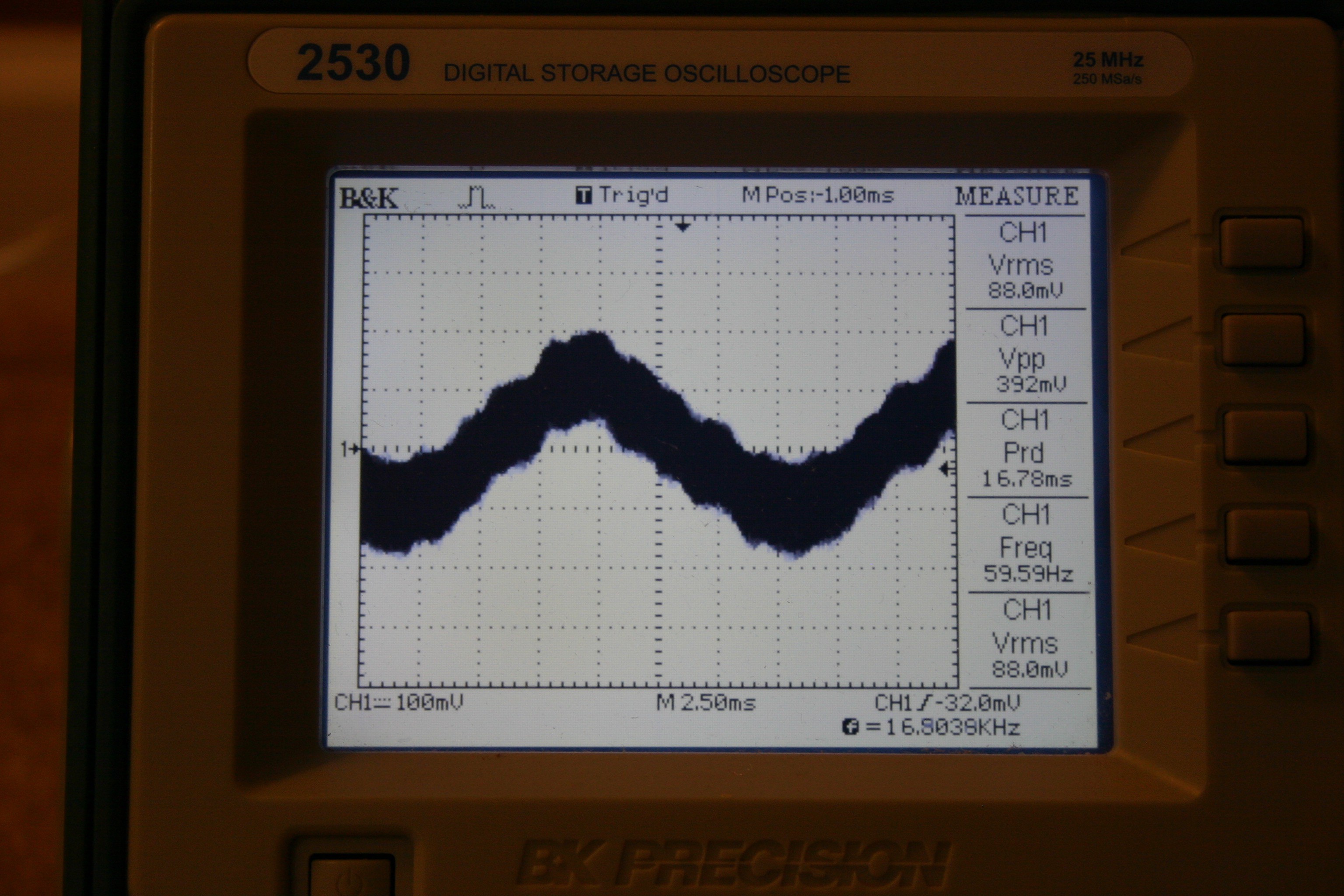
Next, I hooked up the antenna to an oscilloscope.
![]()
There's a wave there and its frequency is 60 cycles--but here is where it gets interesting. The wave is "fat" (has a lot of "fuzz" on it--please excuse my technical language here).
![]()
When a human gets near the antenna, it isn't the 60 cycle wave that changes, it's the "fuzz."
![]()
The easiest way to read the change in "fuzz" is to get rid of the 60 cycle component. I chose to read at the same spot on the 60 cycle wave by reading analog values at 16.7 millisecond multiples (like 50 or 500).
Here's my Arduino code:
int val=0;//storage
int val1=0;//second storage
int val2=0;//more storage
int val3=0;//another storage
const int led=5;//led pin
const int relay=4;//relay pin
int antenna=1;//analog assignment
void setup() {
pinMode(led,OUTPUT);//set led for output
pinMode(relay,OUTPUT);//set relay for output
digitalWrite(led,HIGH);//startup test
digitalWrite(relay,LOW);//startup test
delay(2000);
digitalWrite(led,LOW);//set for run
}
void loop() {
val=analogRead(antenna);//read antenna
delay(500);//wait a bit
val1=analogRead(antenna);//read antenna again
val2=val+10;
val3=val-10;
if (val1>val2 || val1<val3) {
digitalWrite(led,HIGH);//something happened
digitalWrite(relay,HIGH);//close relay contact
delay(1000);
digitalWrite(led,LOW);//reset led
digitalWrite(relay,LOW);//open relay
delay(5000);//let speech module talk
}}Two or three things of interest should be noted:
1) The twisted wire that does not go to A0 works just as well in +5 or gnd.
2) 500 milliseconds delay between readings provides more sensitivity than 50 milliseconds.
3) This works better when powered by battery than a wall wart. Power supply noise or other nearby electrical noise will foul the results.
-
More About the "Connor Nishijima Effect"
05/26/2016 at 20:10 • 2 commentsI've been working on this "human detector" sensor and I have more information to share. First, I wound (two) four inch long insulated wires around each other (not electrically connected). One goes to pin A0 of an Arduino Uno, the other to ground.
![]()
While playing around with software, I noticed that I could only get predictable results when my delay between two readings was an exact multiple of 16.7 milliseconds--something to do with 60 cycle (powerline) frequency.
Next, I hooked up the antenna to an oscilloscope.
![]()
There's a wave there and its frequency is 60 cycles--but here is where it gets interesting. The wave is "fat" (has a lot of "fuzz" on it--please excuse my technical language here).
![]()
When a human gets near the antenna, it isn't the 60 cycle wave that changes, it's the "fuzz."
![]()
The easiest way to read the change in "fuzz" is to get rid of the 60 cycle component. I chose to read at the same spot on the 60 cycle wave by reading analog values at 16.7 millisecond multiples (like 50 or 500).
Here's my Arduino code:
int val=0;//storage
int val1=0;//second storage
int val2=0;//more storage
int val3=0;//another storage
const int led=5;//led pin
const int relay=4;//relay pin
int antenna=1;//analog assignment
void setup() {
pinMode(led,OUTPUT);//set led for output
pinMode(relay,OUTPUT);//set relay for output
digitalWrite(led,HIGH);//startup test
digitalWrite(relay,LOW);//startup test
delay(2000);
digitalWrite(led,LOW);//set for run
}
void loop() {
val=analogRead(antenna);//read antenna
delay(500);//wait a bit
val1=analogRead(antenna);//read antenna again
val2=val+10;
val3=val-10;
if (val1>val2 || val1<val3) {
digitalWrite(led,HIGH);//something happened
digitalWrite(relay,HIGH);//close relay contact
delay(1000);
digitalWrite(led,LOW);//reset led
digitalWrite(relay,LOW);//open relay
delay(5000);//let speech module talk
}}Two or three things of interest should be noted:
1) The twisted wire that does not go to A0 works just as well in +5 or gnd.
2) 500 milliseconds delay between readings provides more sensitivity than 50 milliseconds.
3) This works better when powered by battery than a wall wart. Power supply noise or other nearby electrical noise will foul the results.
-
Connor Nishijima Effect
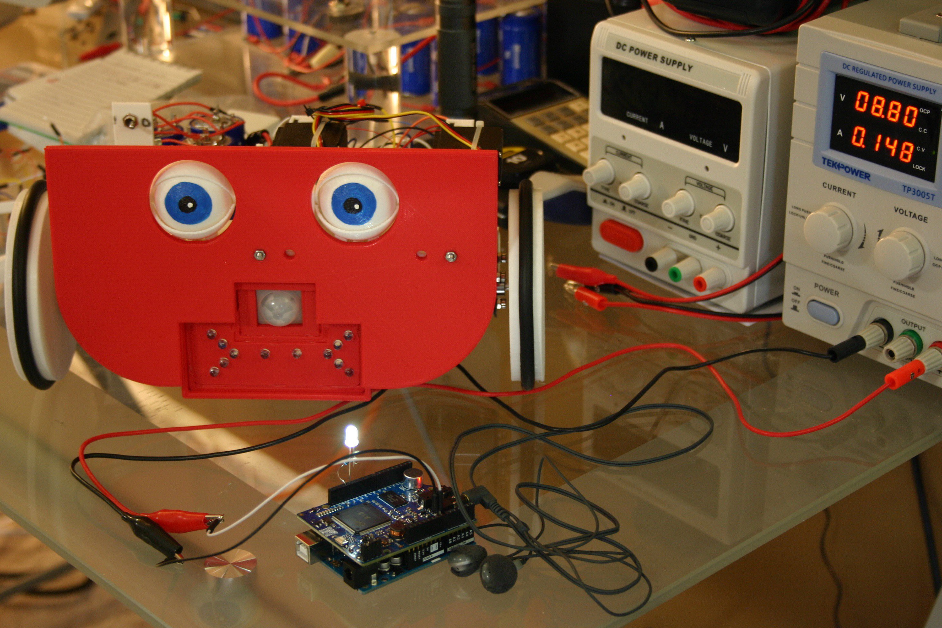
05/25/2016 at 14:34 • 0 commentsI've named this "human detection" method the "Connor Nishijima Effect." My old method--stop the robot, wait a few seconds for the PIR sensor to settle, then check the PIR sensor for activitiy--is not great. Motion detectors detect motion and a moving robot sees everything as motion.
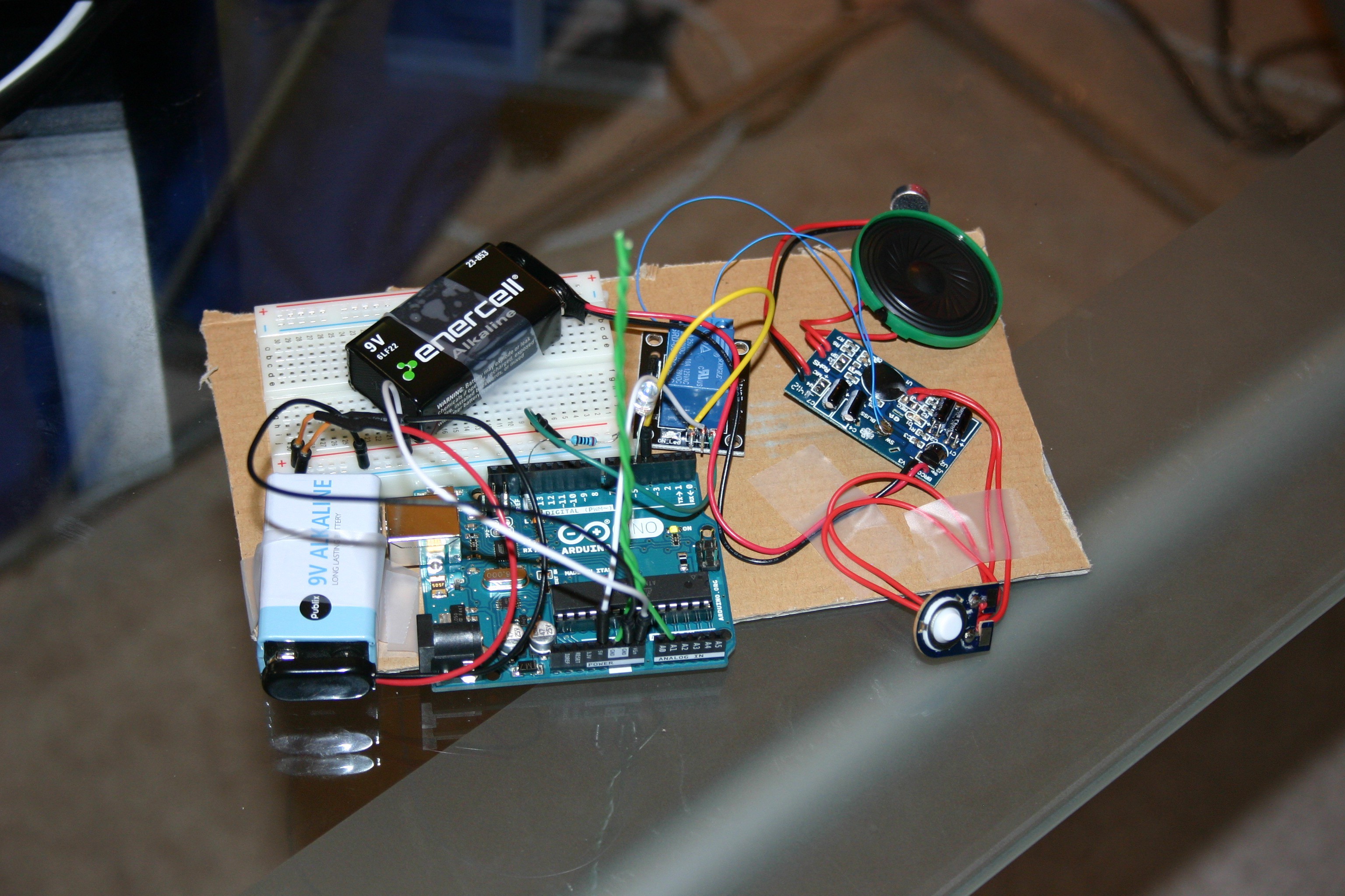
I rigged up an Arduino, twisted wire and a speech module to test the system (Arduino file is available in this project as "Antenna test.")
![]()
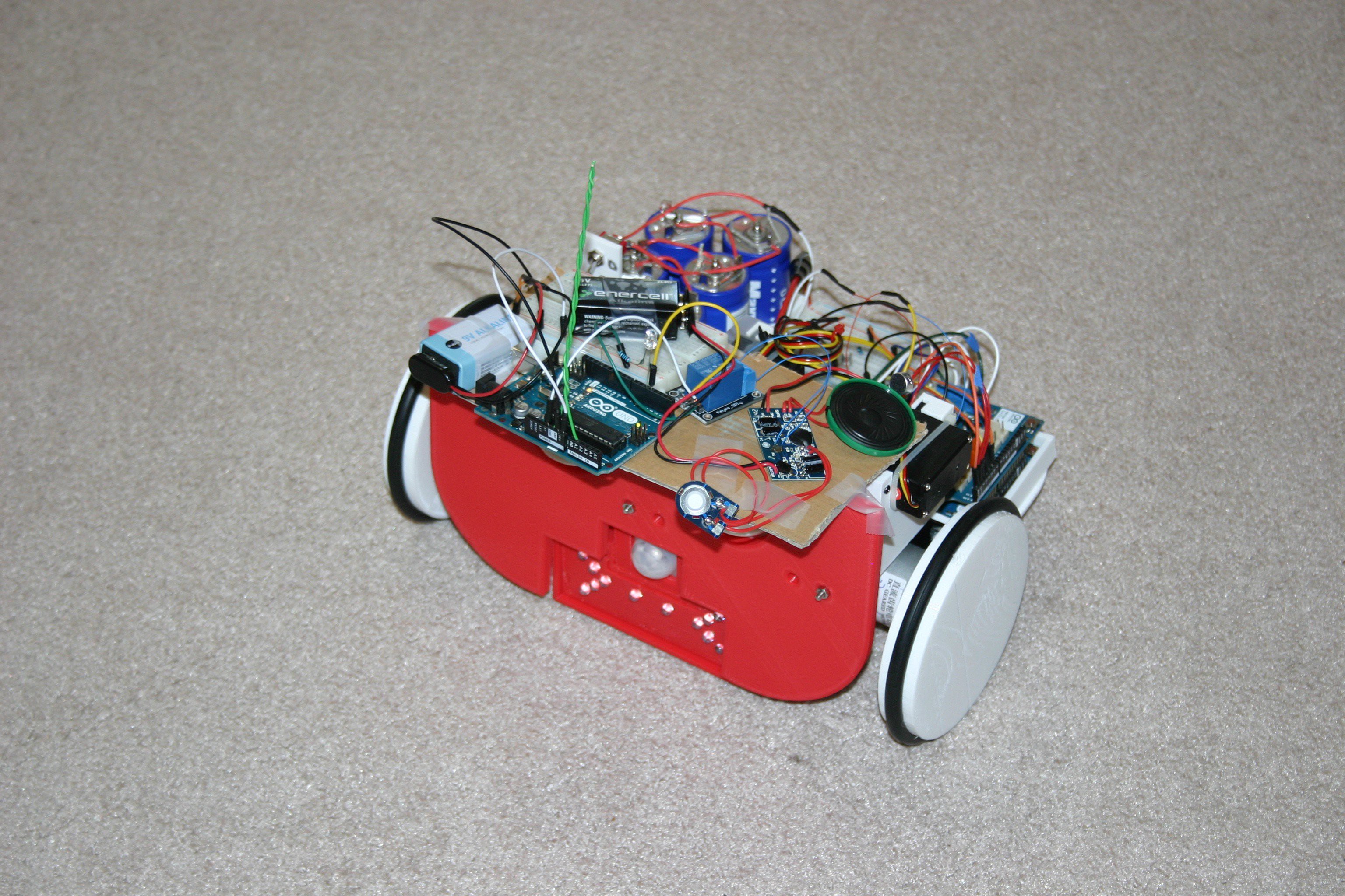
It worked well in a stationary position, but I wondered what would happen if it were moving. I taped it to a piece of cardboard, then taped the cardboard to the top of Mato.
![]()
Next, I let it run and approached Mato. The speech module fired when I approached--and only when I approached--Hooray!
The tests are crude and this is early in the game--but it looks promising!
-
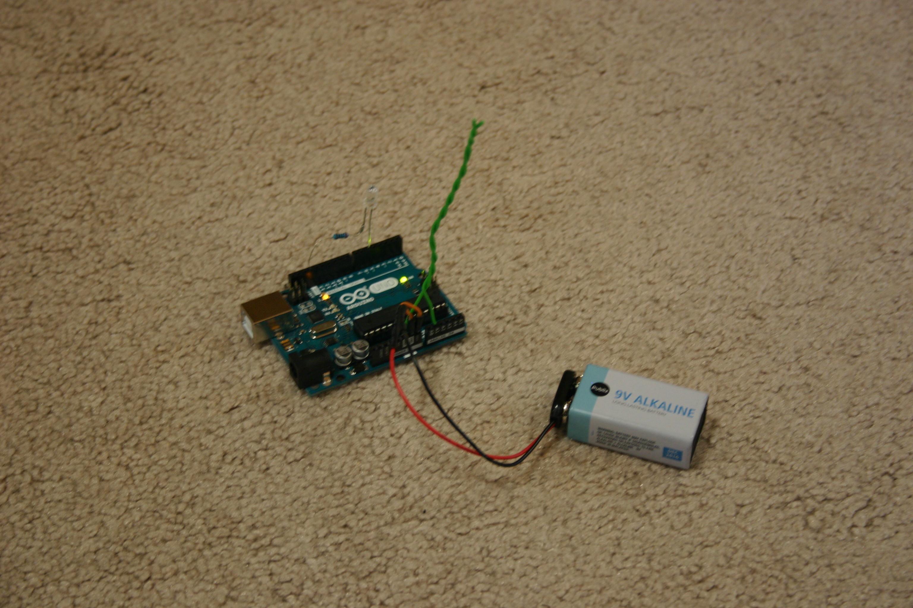
Human Detector Using Arduino and Bit of Wire
05/25/2016 at 00:30 • 2 commentsI read about Connornishijima and the twisted bit of wire "human detection." I tried it with four inches of twisted wire and a bit of code (see antenna test for this project) and a battery powered Arduino. It seems to work well (though without directional capability), so I may use it on Mato when I sort out the power consumption and speech issues.
-
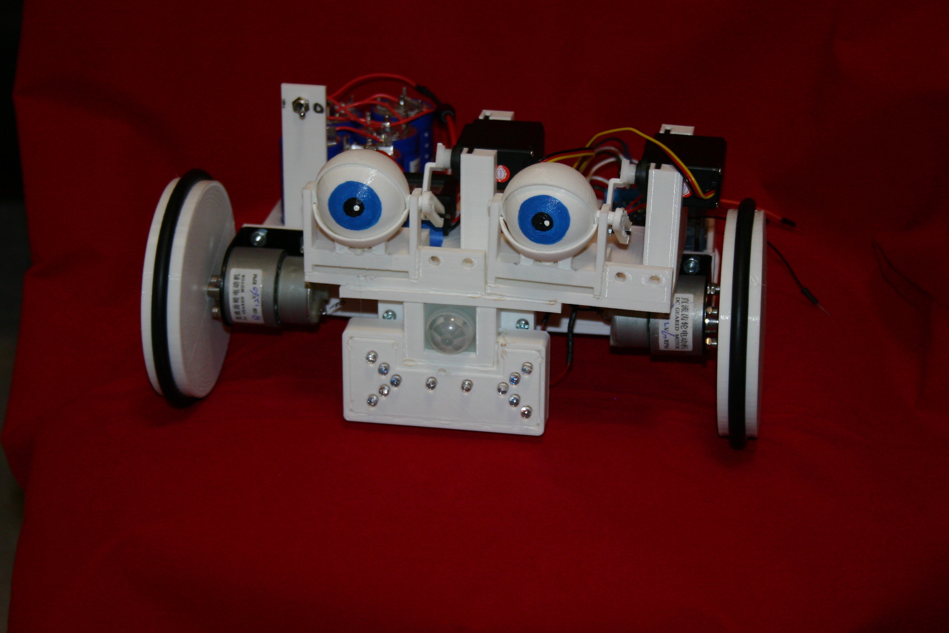
Mato Smiles and Blinks
05/19/2016 at 21:38 • 0 commentsI'm adding construction details here . . . after the video.
Mato II Construction
Parts:
(2) 12 V dc 60 rpm gear motorshttp://www.amazon.com/Nextrox-Mini-Torque-Electric-Motor/dp/B00BX54O8A?ie=UTF8&psc=1&redirect=true&ref_=oh_aui_detailpage_o06_s01
(2) Motor bracketshttp://www.amazon.com/uxcell-Geared-Mounting-Bracket-Coupling/dp/B00TK0X03U?ie=UTF8&psc=1&redirect=true&ref_=oh_aui_detailpage_o06_s00
(5) 350 farad 2.7 volt capacitorshttp://www.amazon.com/Maxwell-Technologies-Supercapacitors-Ultracapacitors-2-7Volts/dp/B0137ILPOQ/ref=sr_1_2?s=industrial&ie=UTF8&qid=1463673653&sr=1-2&keywords=350+f+capacitor
These are available for less cost per unit (minimum order ten) at: https://www.tecategroup.com/store/index.php?main_page=product_info&products_id=1221
(1) DC step up/step down converter modulehttp://www.amazon.com/Converter-3-5-28V-1-25-26V-Adjustable-LM2596S/dp/B008ATU2X8?ie=UTF8&psc=1&redirect=true&ref_=oh_aui_detailpage_o06_s00
(2) Eureka round vacuum beltshttp://www.amazon.com/Eureka-Style-RD-Vacuum-Belts/dp/B00002N62X?ie=UTF8&psc=1&redirect=true&ref_=oh_aui_detailpage_o03_s00
(2) Hitec HS 311 servo motorshttp://www.amazon.com/Hitec-31311S-HS-311-Standard-Universal/dp/B0006O3WVE?ie=UTF8&psc=1&redirect=true&ref_=oh_aui_detailpage_o09_s00
(1) DC digital meterhttp://www.amazon.com/DROK-Digital-Voltmeter-Voltage-Display/dp/B00C2NTJHS?ie=UTF8&psc=1&redirect=true&ref_=oh_aui_detailpage_o09_s00
(1) Arduino Uno
(1) Arduino Motor shield
(12) LED’s, white
(2) .47 microfarad capacitors, Jameco.com #25558
(1) PIR sensor
Misc.:
5 amp fuse
m3X 4 with nut
#8x ¾ nuts & bolts
#6 x ½ nuts & bolts
m3 x 12 with nut
(5) 100 ohm resistor
2n2222a transistor
1n4004 diode
2-56 x ¾ screw and nut
breadboard
breadboard jumper wires
solder
heat shrink tubing
duct tape
spst switch
3d Printed Parts
Eyeball, Lower Eyelid, and base are found here and should be printed at 95% size: http://www.thingiverse.com/thing:319978/#files
These are by “sideburn” with a creative commons, attribution, non commercial license
These files are available on hackaday.io—print the .stl files; the .123dx are available for modification purposes.
arduino holder design.123dx
arduino holder.stl
body exwide.stl
breadboard mount design.123dx
breadboard mount.stl
caster ball.stl
caster base.stl
eye servob design.123dx
eye servob.stl
eyeball roda.stl
eyelid connb design.123dx
eyelid connb.stl
eyelid extended.stl
mouth backing design.123dx
mouth backing.stl
mouthgard design.123dx
mouthguard.stl
mouthpiece design.123dx
mouthpiece.stl (print at 109% size)
nose eye bkta design.123dx
nose eye bkta.stl
nose pirb design.123dx
nose pirb.stl
servo hornc special design.123dx
servo hornc special.stl
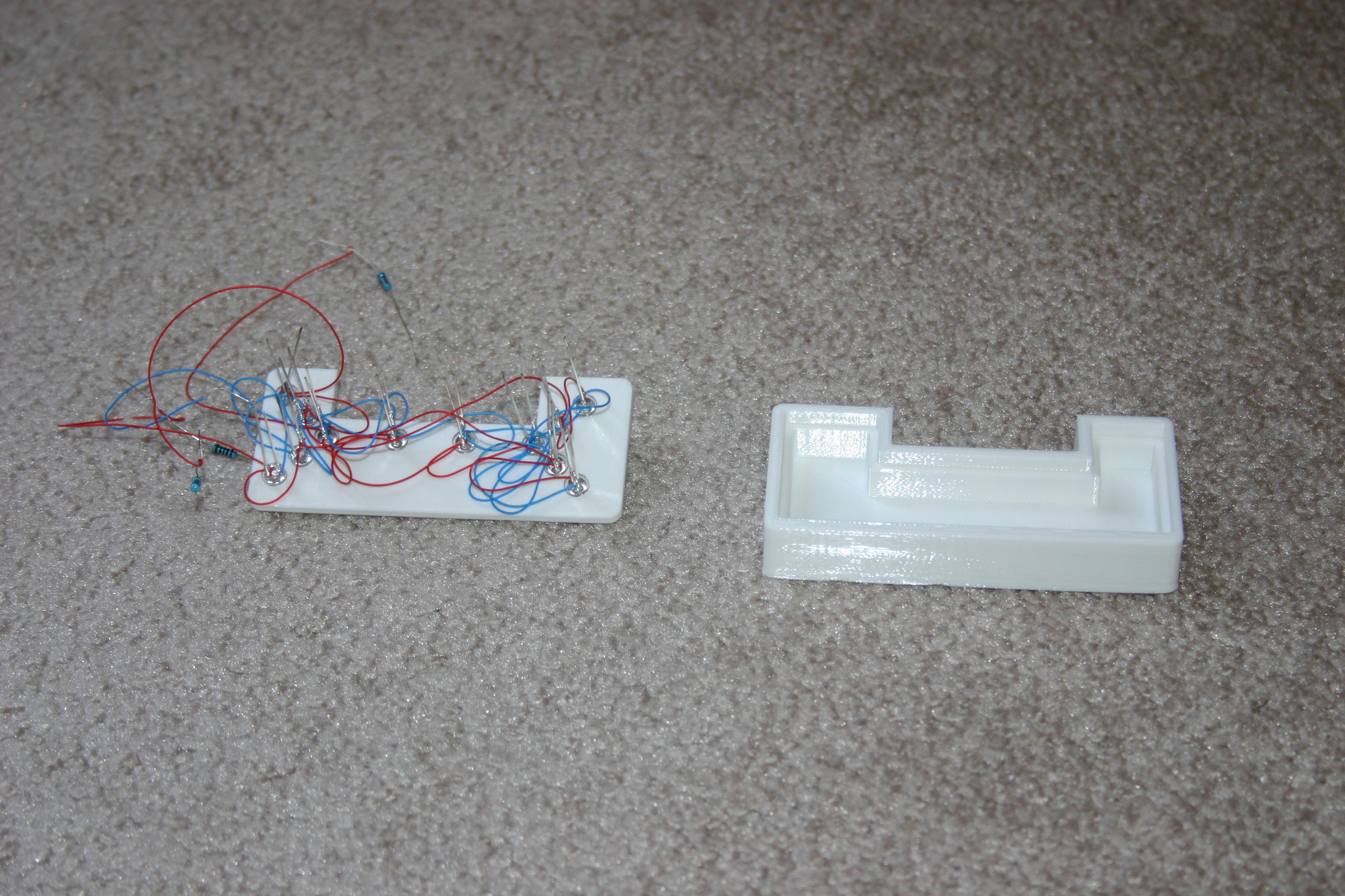
ultracap holder design.123dx
ultracap holder.stl
wheel design.123dx
wheel.stl
Now, let’s get started! Take the eyeball base and insert the lower eyelid, then upper eyelid, then eyeball and eyeball rod. Secure the lower eyelid, rod and eyeball base together by melting (with a soldering iron) or using glue.
![]()
Attach the connector to the eyball assembly.
![]()
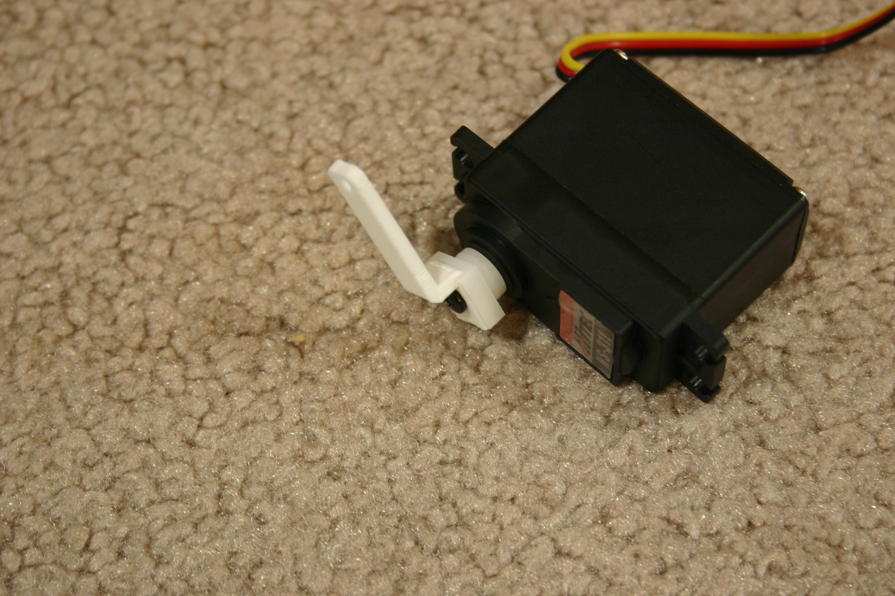
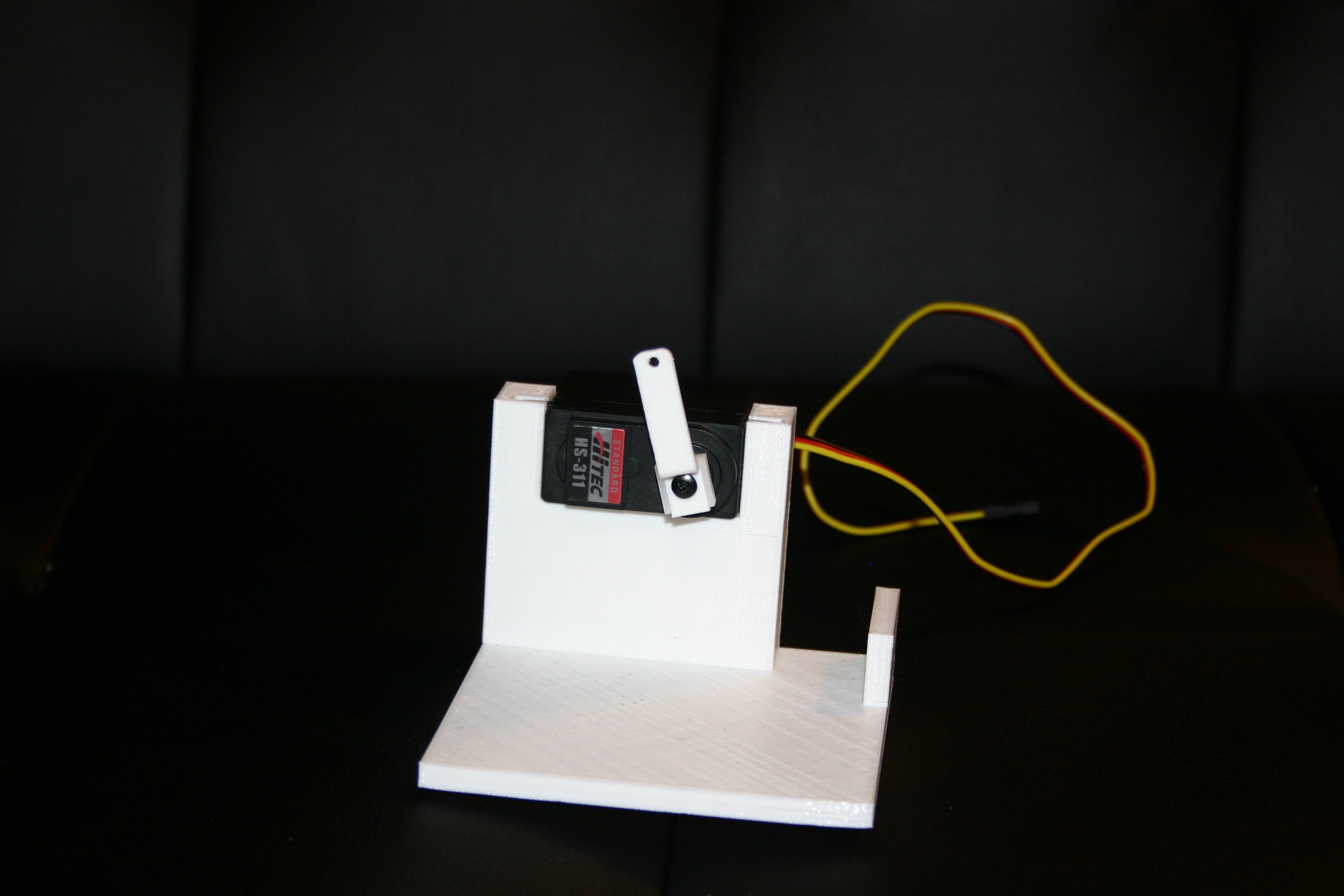
Attach the printed servo horn to the servo motor.
![]()
Place the motor/servo horn into the base.
![]()
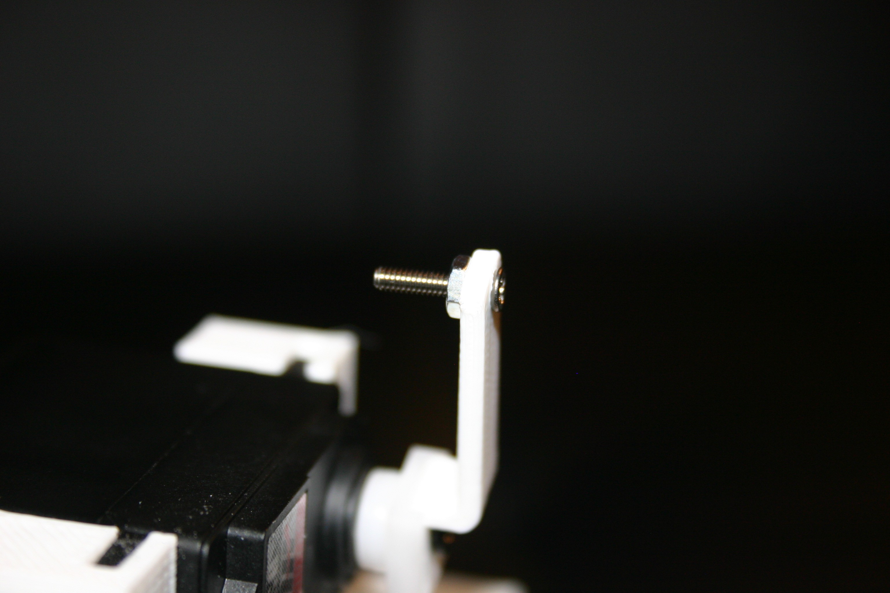
Attach a 2-56 by ½ inch screw to the printed servo horn.
![]()
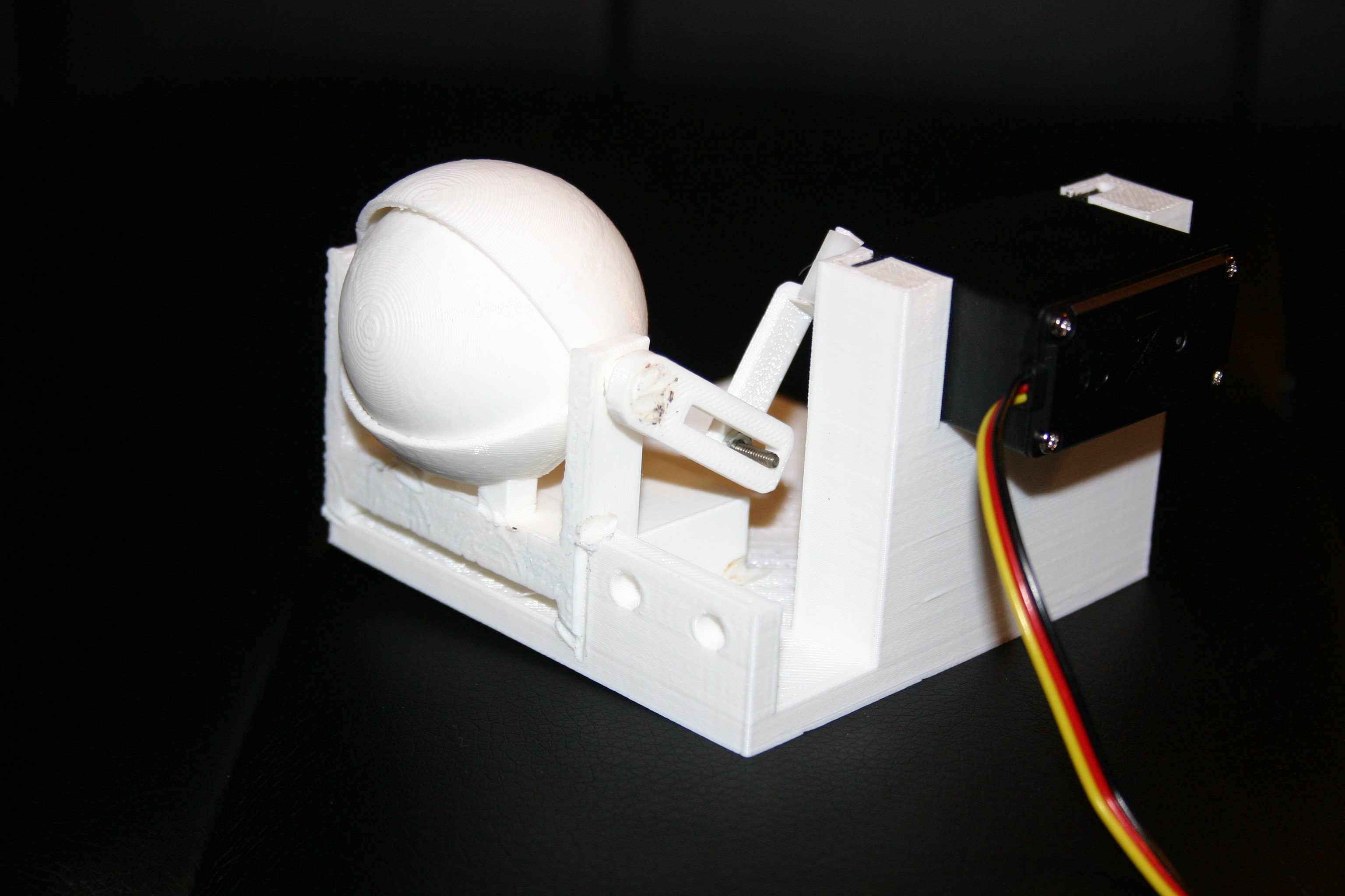
Connect the servo horn to the eyelid connector. Be certain that the servo can travel enough to open and close the eyelid.
![]()
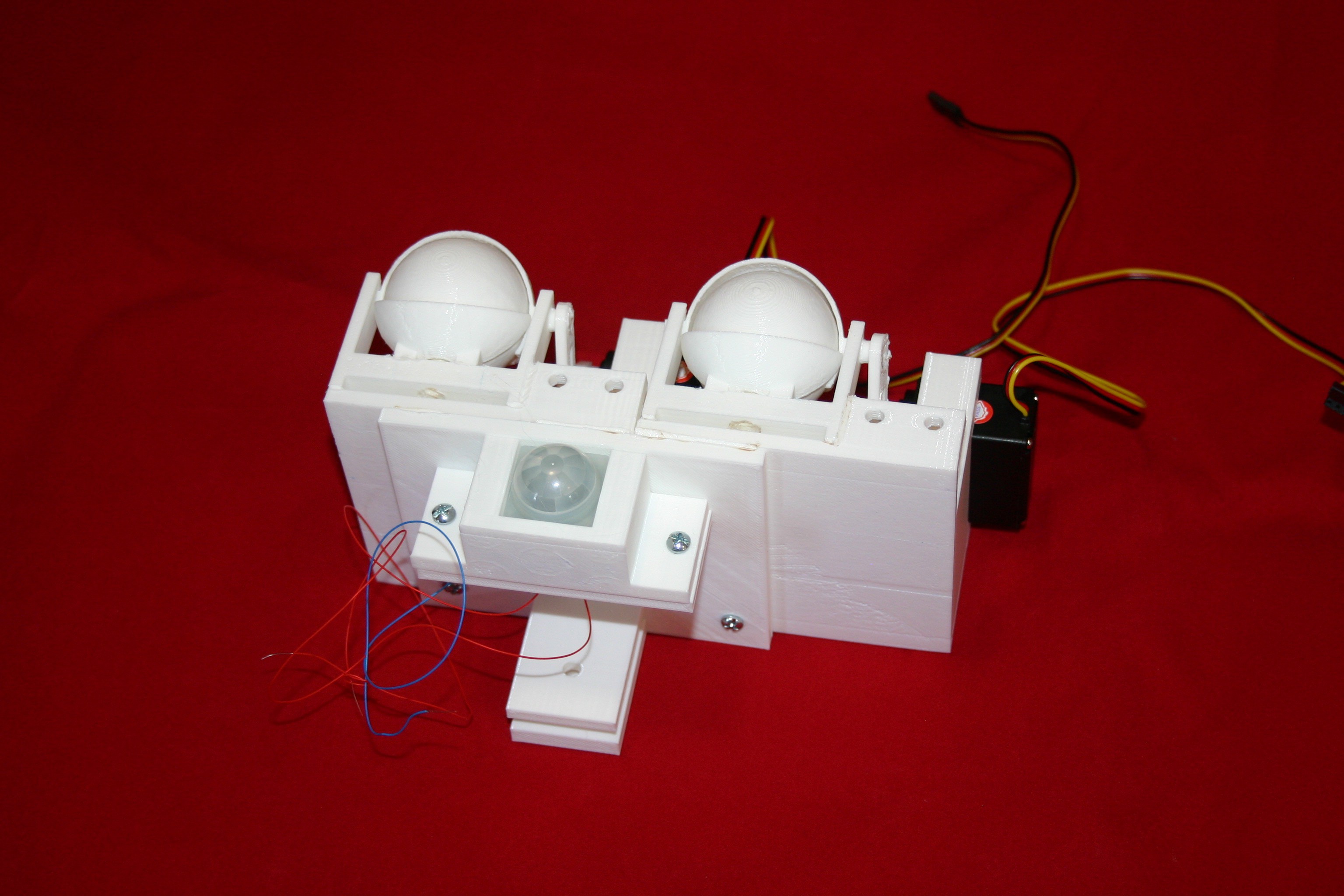
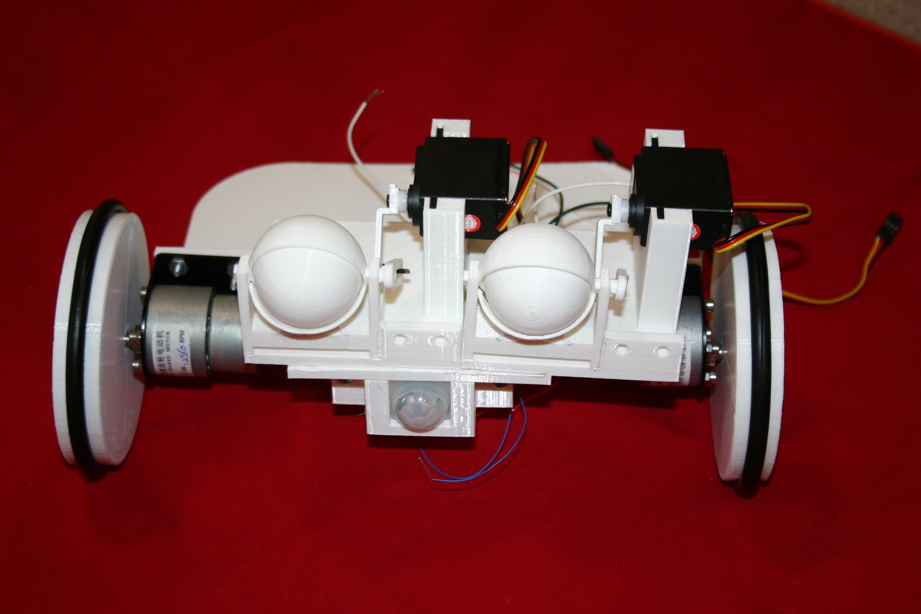
Attach the eyeballs to the nose eye bracket.
![]()
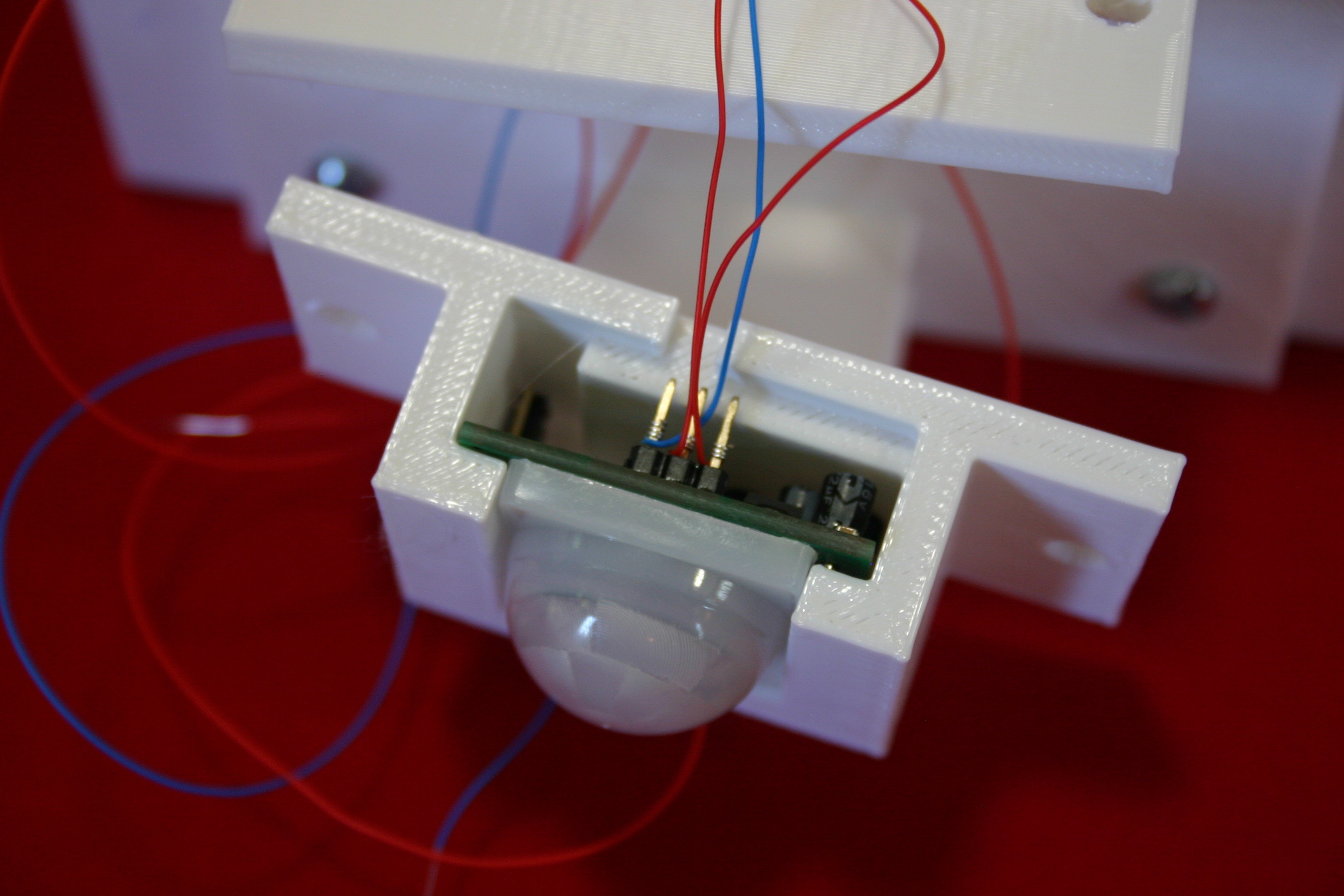
Wire and insert the PIR sensor into the eye bracket.
![]()
Secure the nose (PIR sensor) to the eye/nose bracket.
![]()
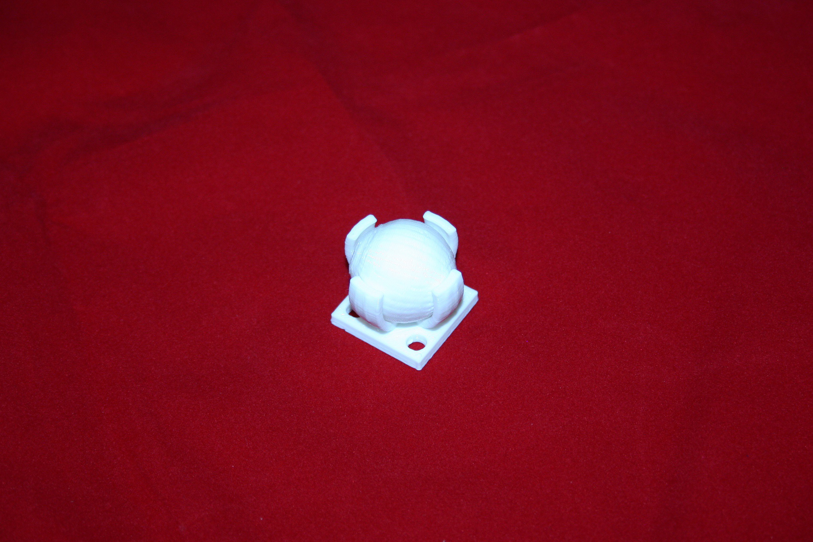
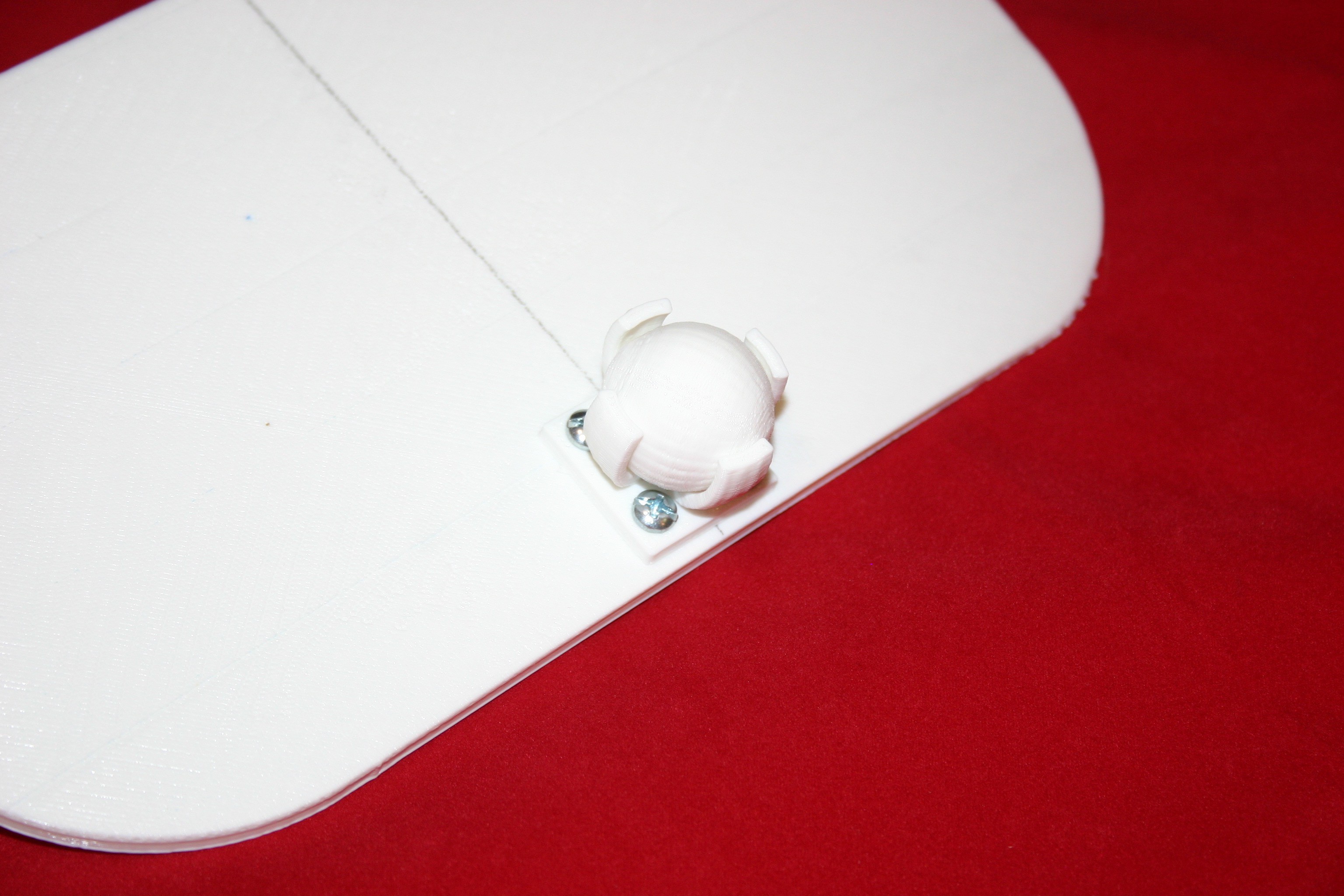
Push the caster ball into the caster bracket.
![]()
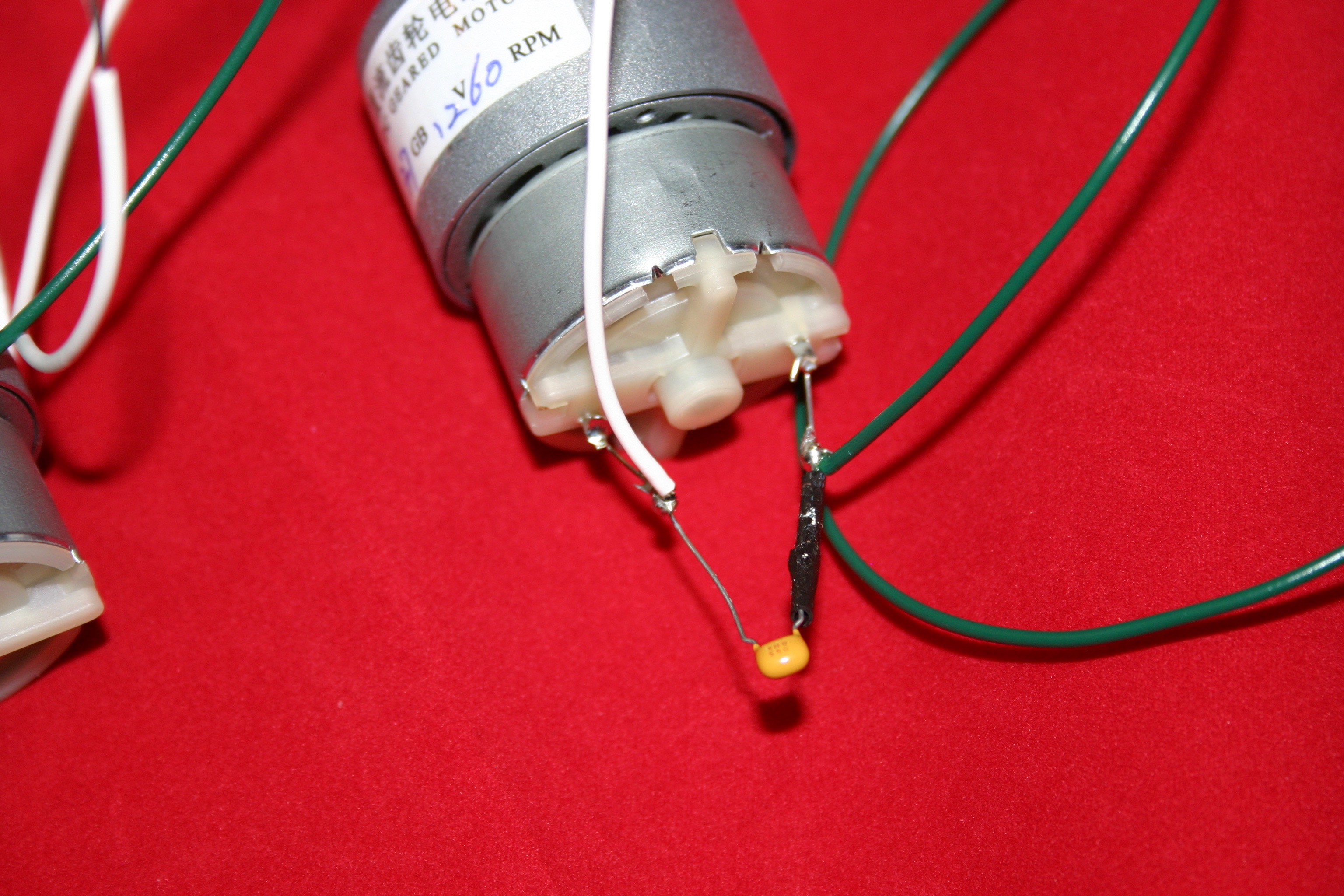
Add wires and a .47 microfarad capacitor to the motors.
![]()
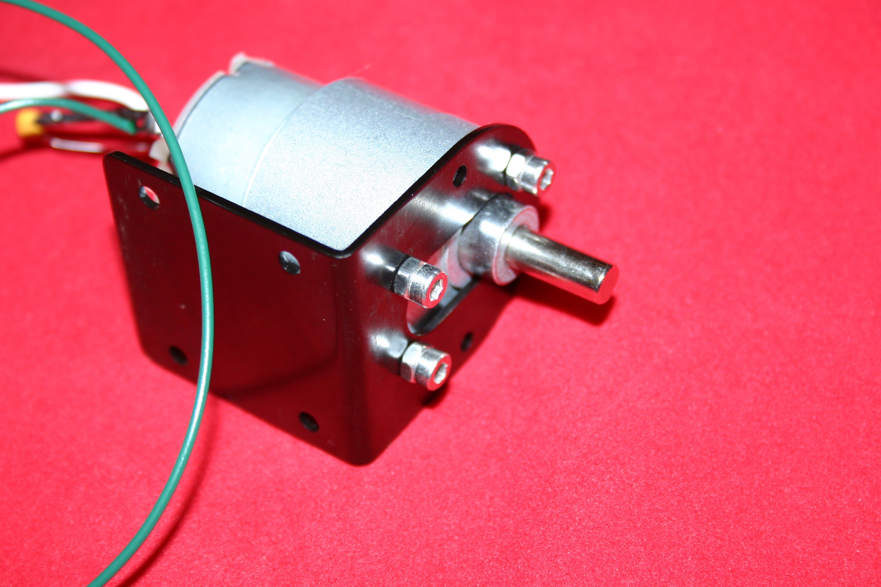
Attach the motors to the motor brackets using m3 x 4 screws (I had m3 x 6 available, so I had to add a nut to make it fit).
![]()
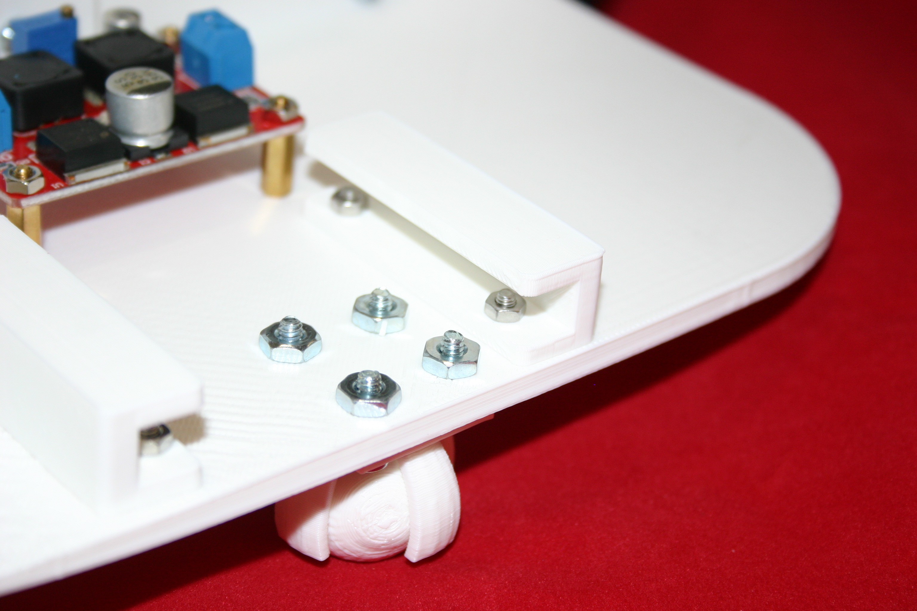
Drill holes and attach the caster wheel to the wide body (yes, I should have printed the holes, but it’s hard to preplan everything).
![]()
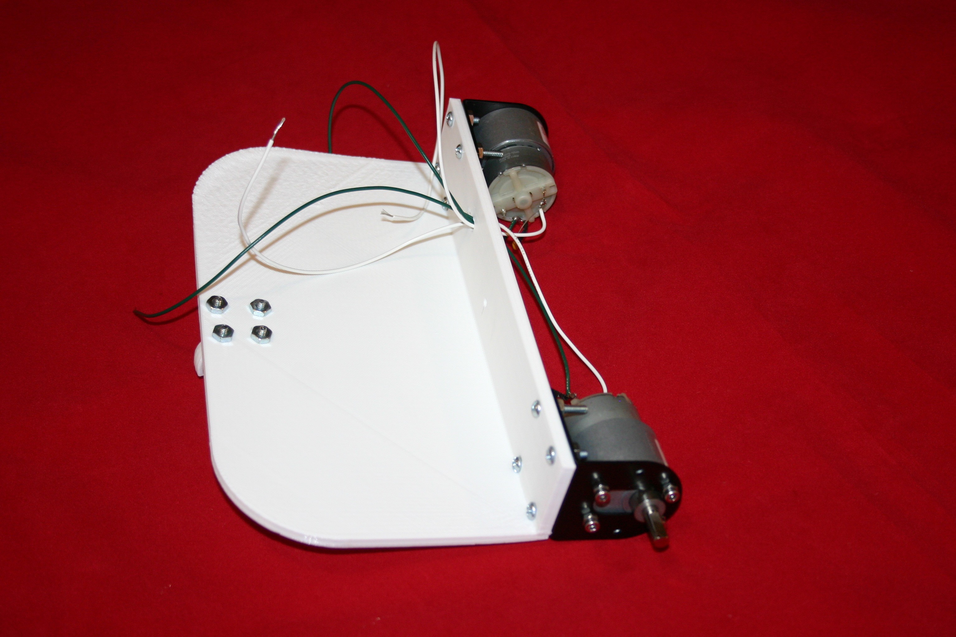
Attach the motors to the wide base (#6 x ½ nuts and bolts).
![]()
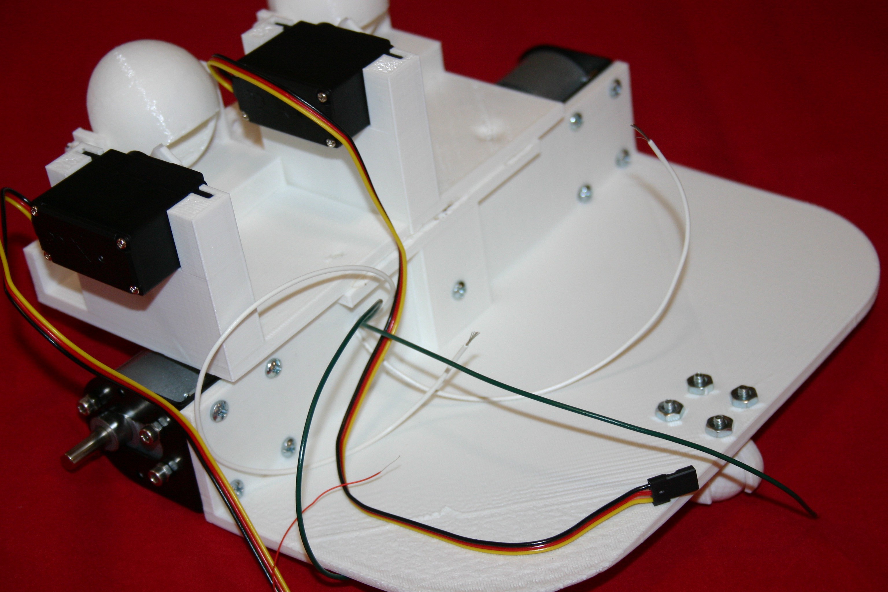
Attach the eye/nose assembly to the wide base.
![]()
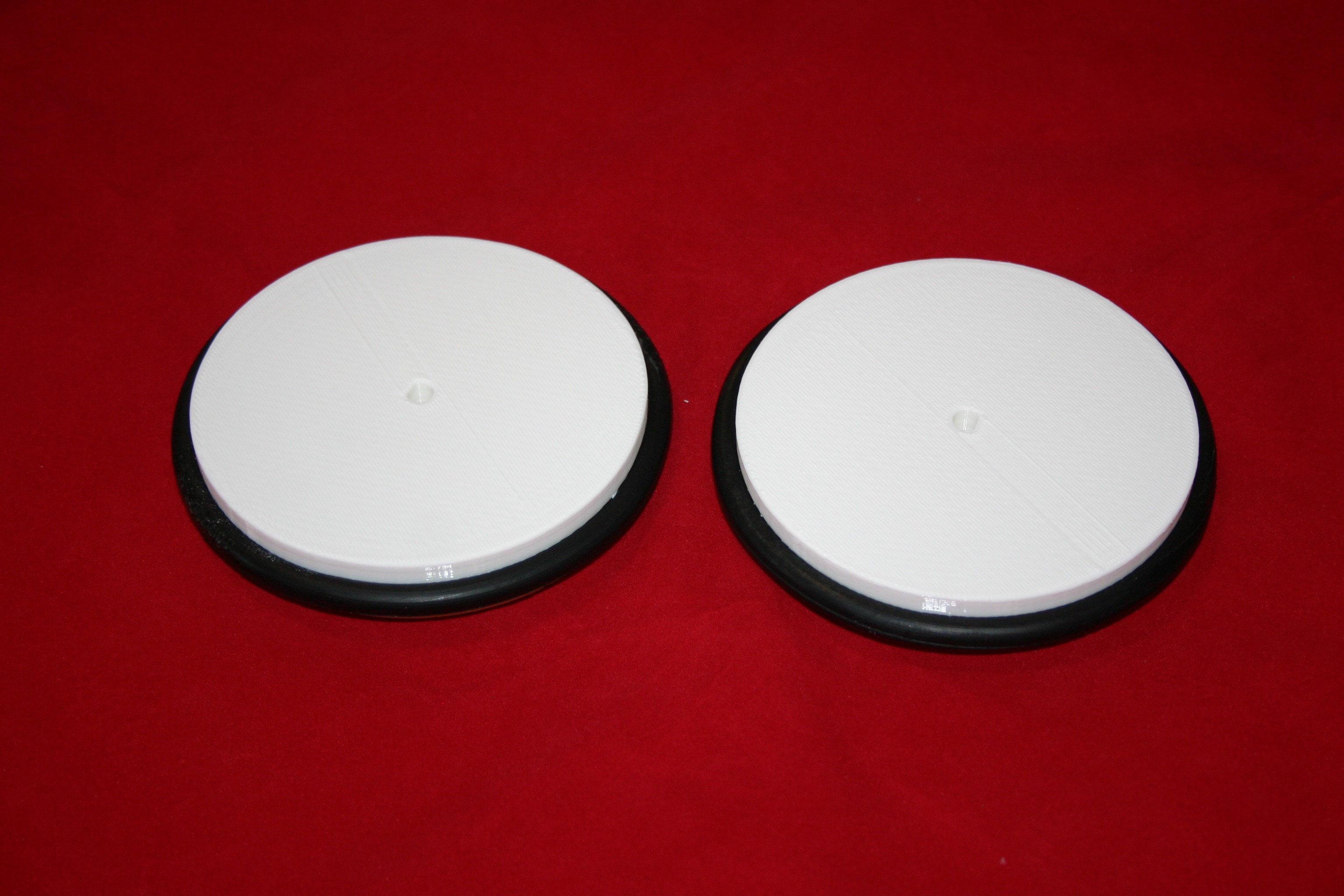
Stretch the Eureka vacuum belts over the printed wheels.
![]()
Insert (friction fit) the wheels onto the motor shaft.
![]()
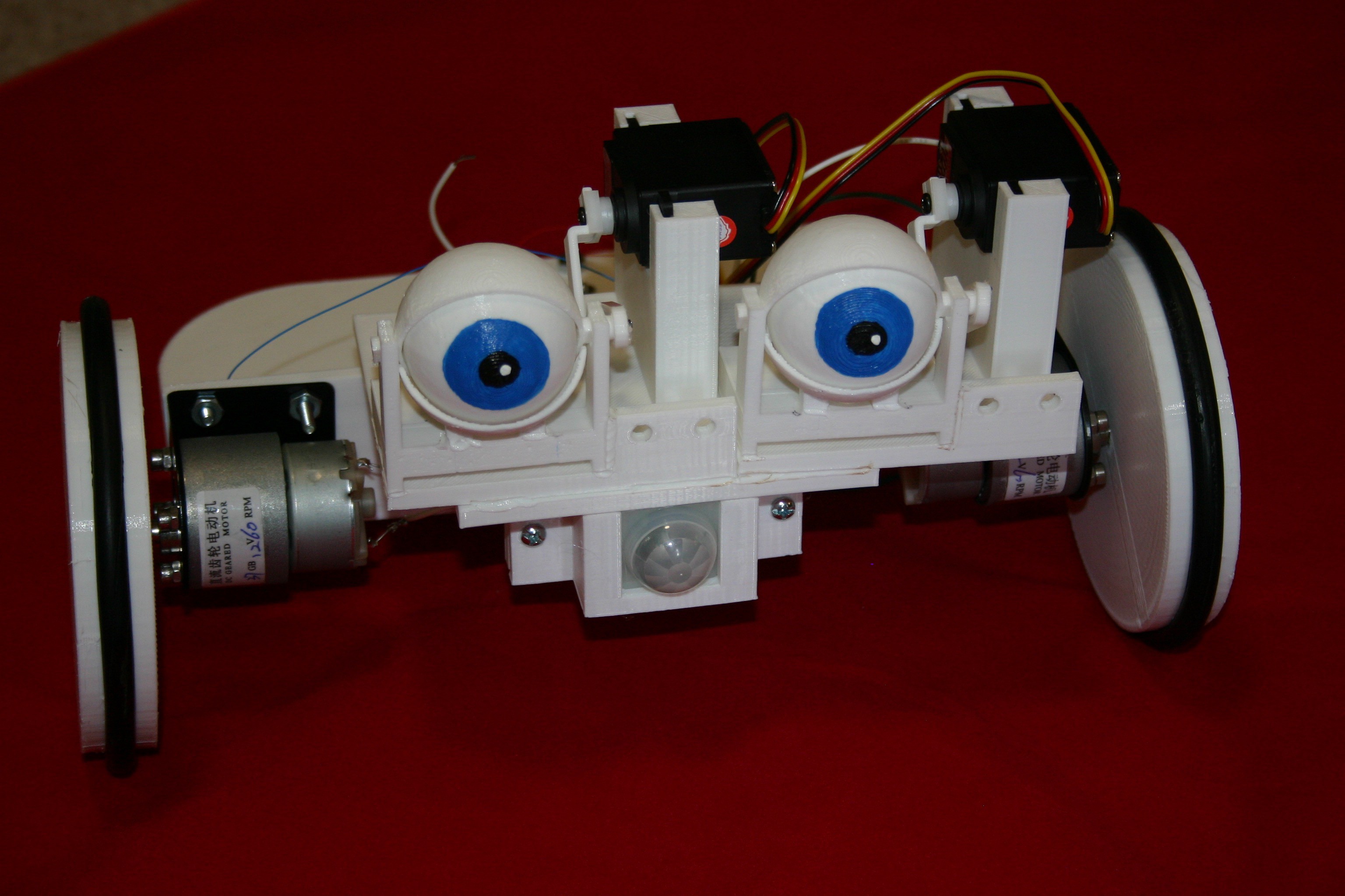
Paint the center of the eyeballs.
![]()
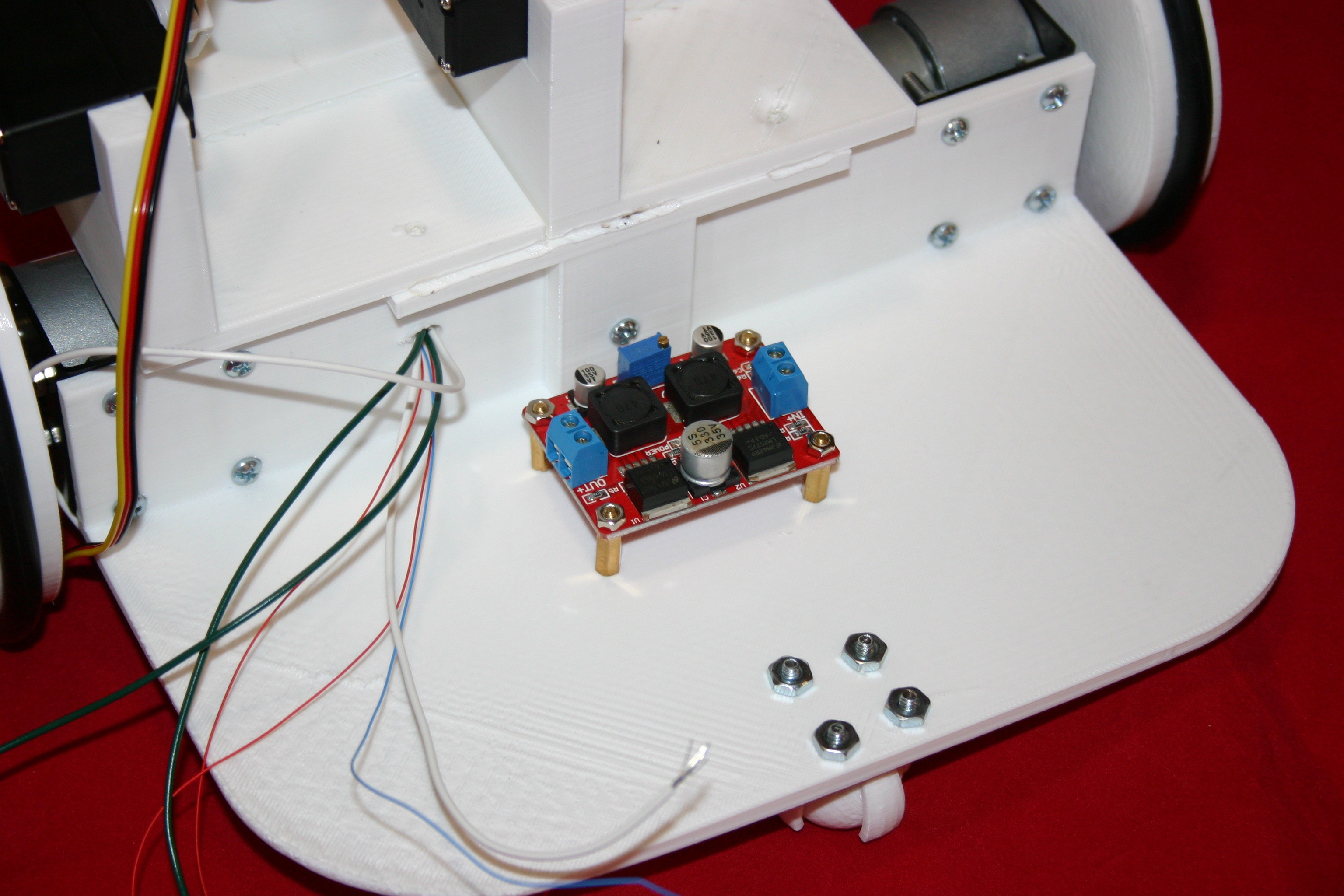
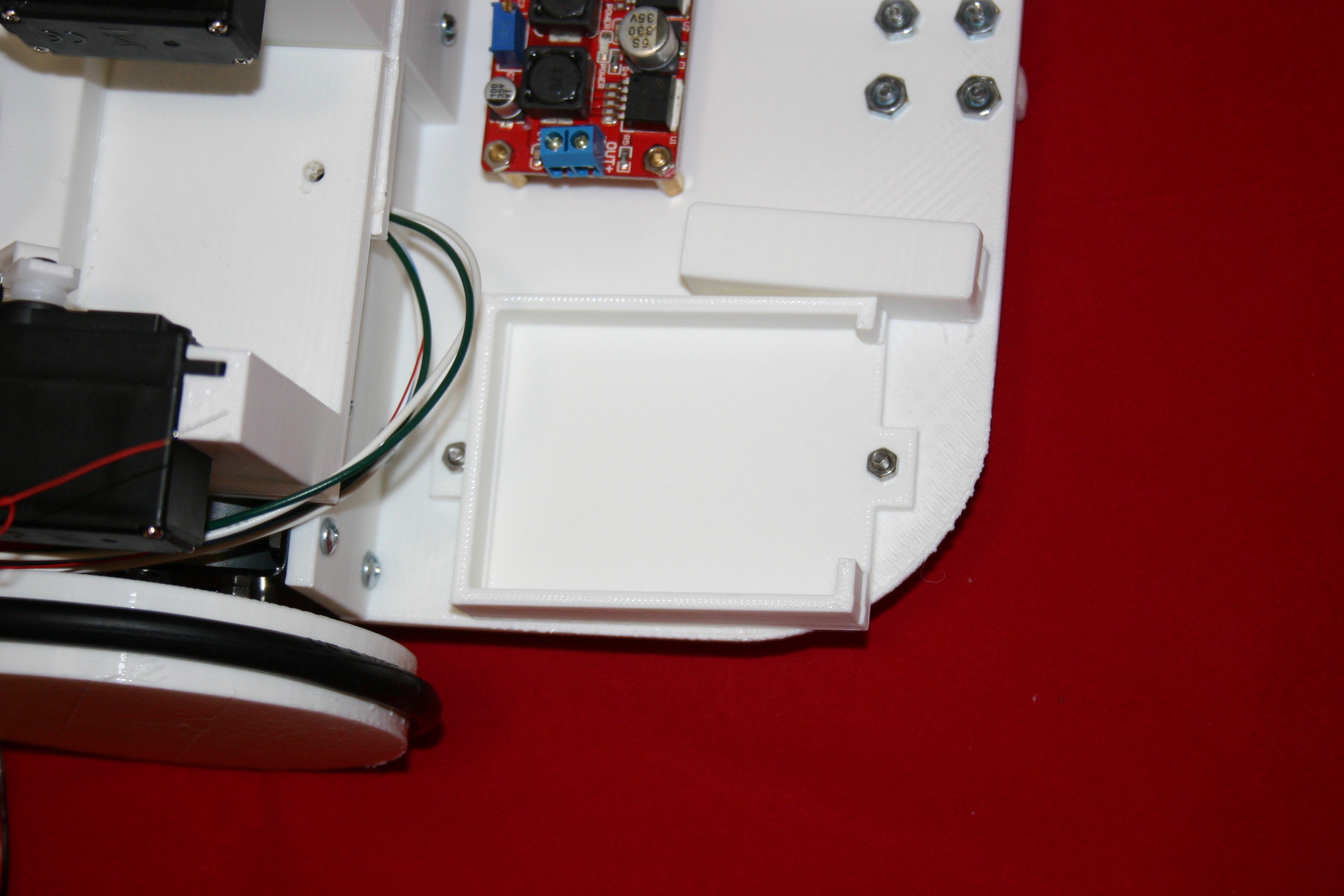
Install the DC buck/boost converter. Drill (2) 1/8 inch holes and use m3 x 12 screws.
![]()
Install the breadboard holders using m3 x 12 screws and nuts.
![]()
Install Arduino holder using m3 x 6 screws and nuts.
![]()
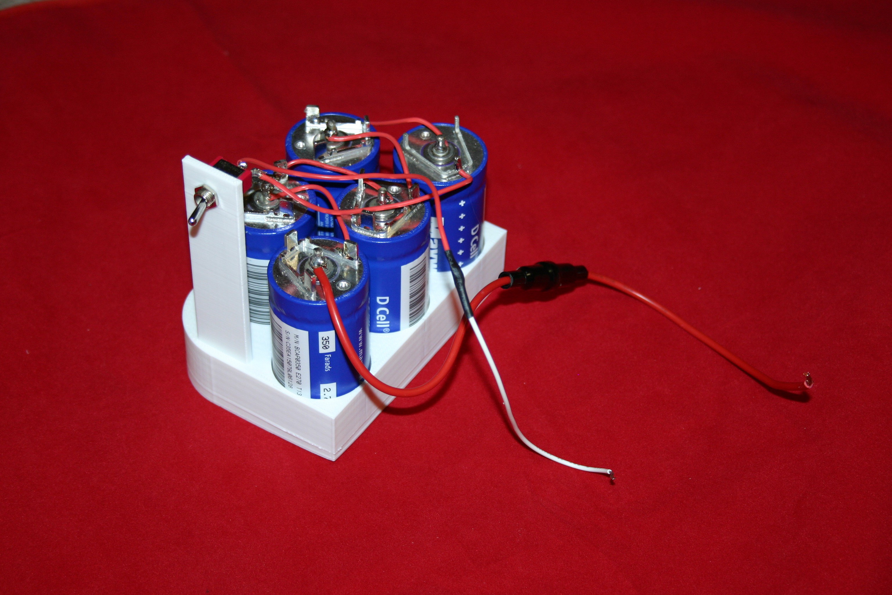
Solder capacitors together in series (using 100 watt or higher soldering iron). Add fuse on negative side and switch on positive end.
![]()
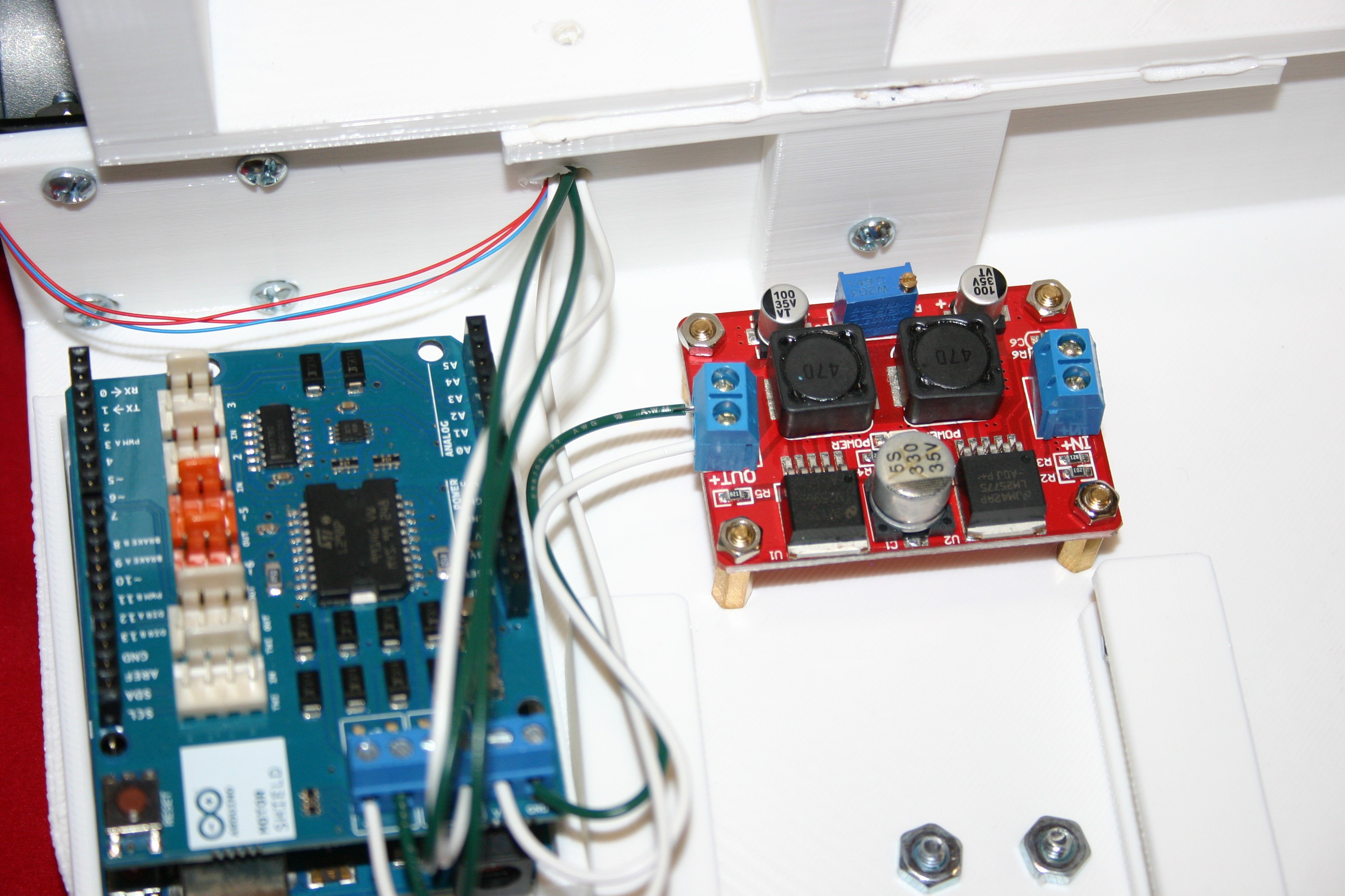
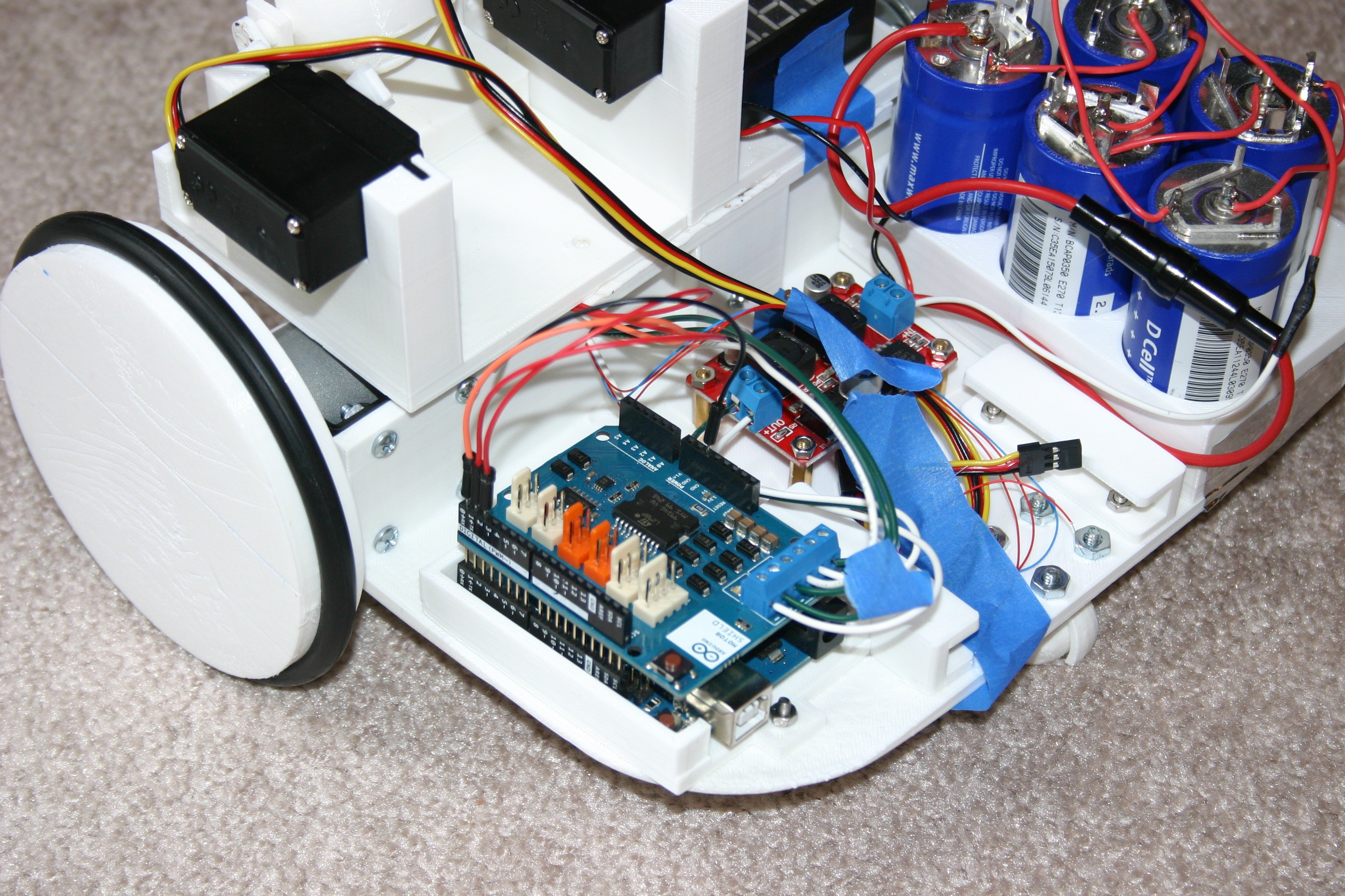
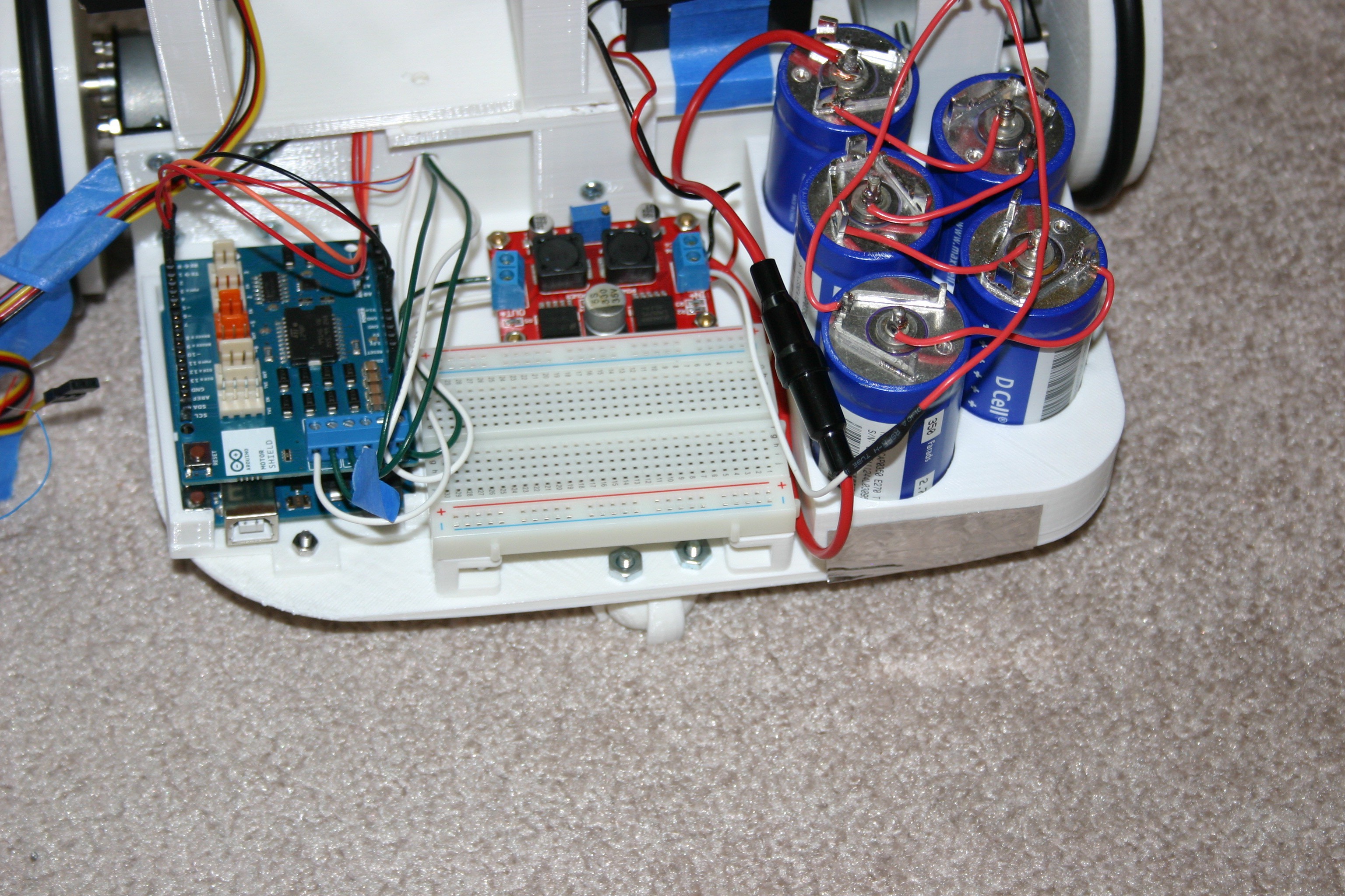
Connect motor wires to Arduino motor shield. Connect input power on motor shield to output of voltage converter.
![]()
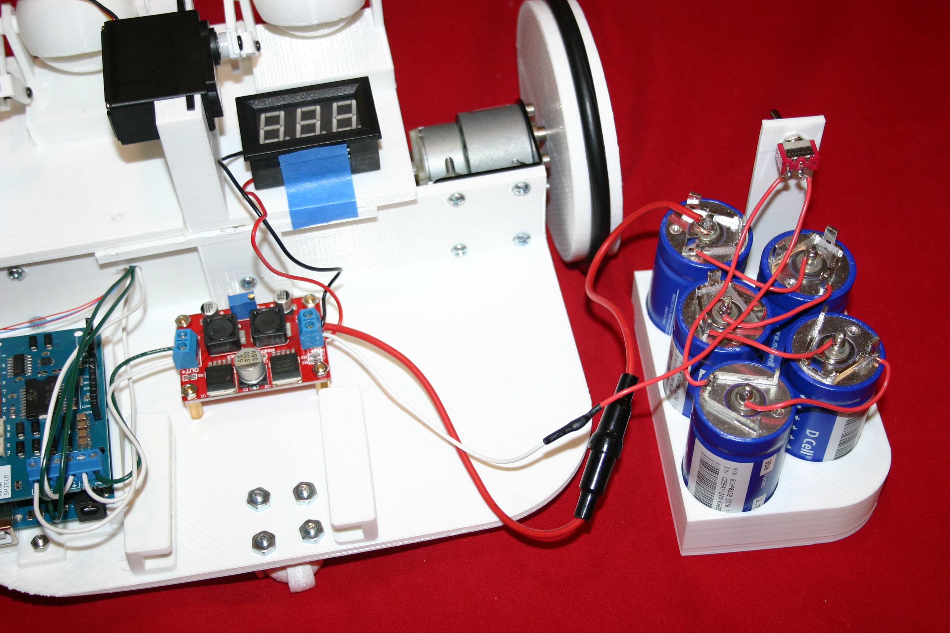
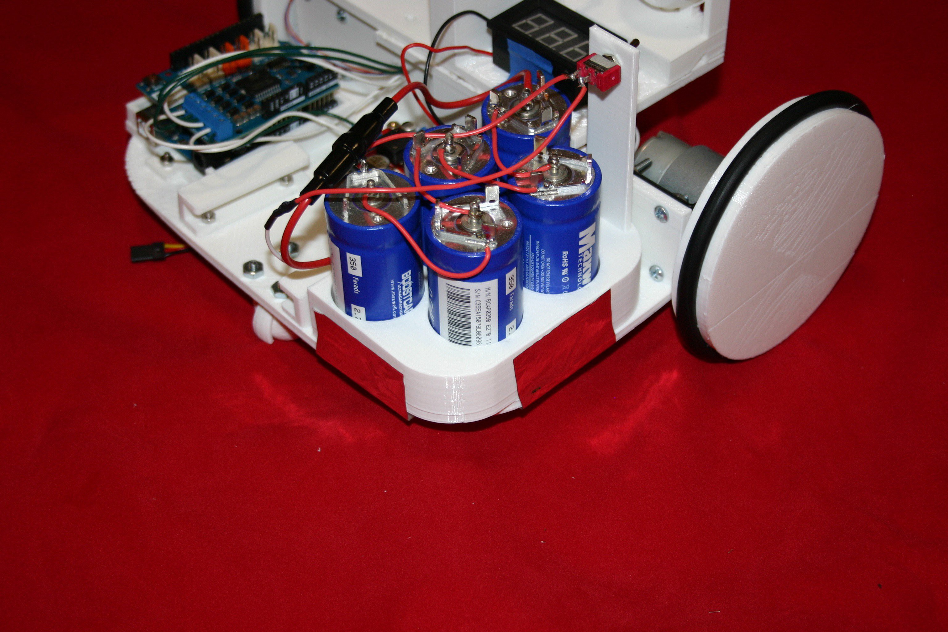
Connect capacitors and voltmeter to input of voltage converter board.
![]()
Secure capacitor assembly to wide base using duct tape.
![]()
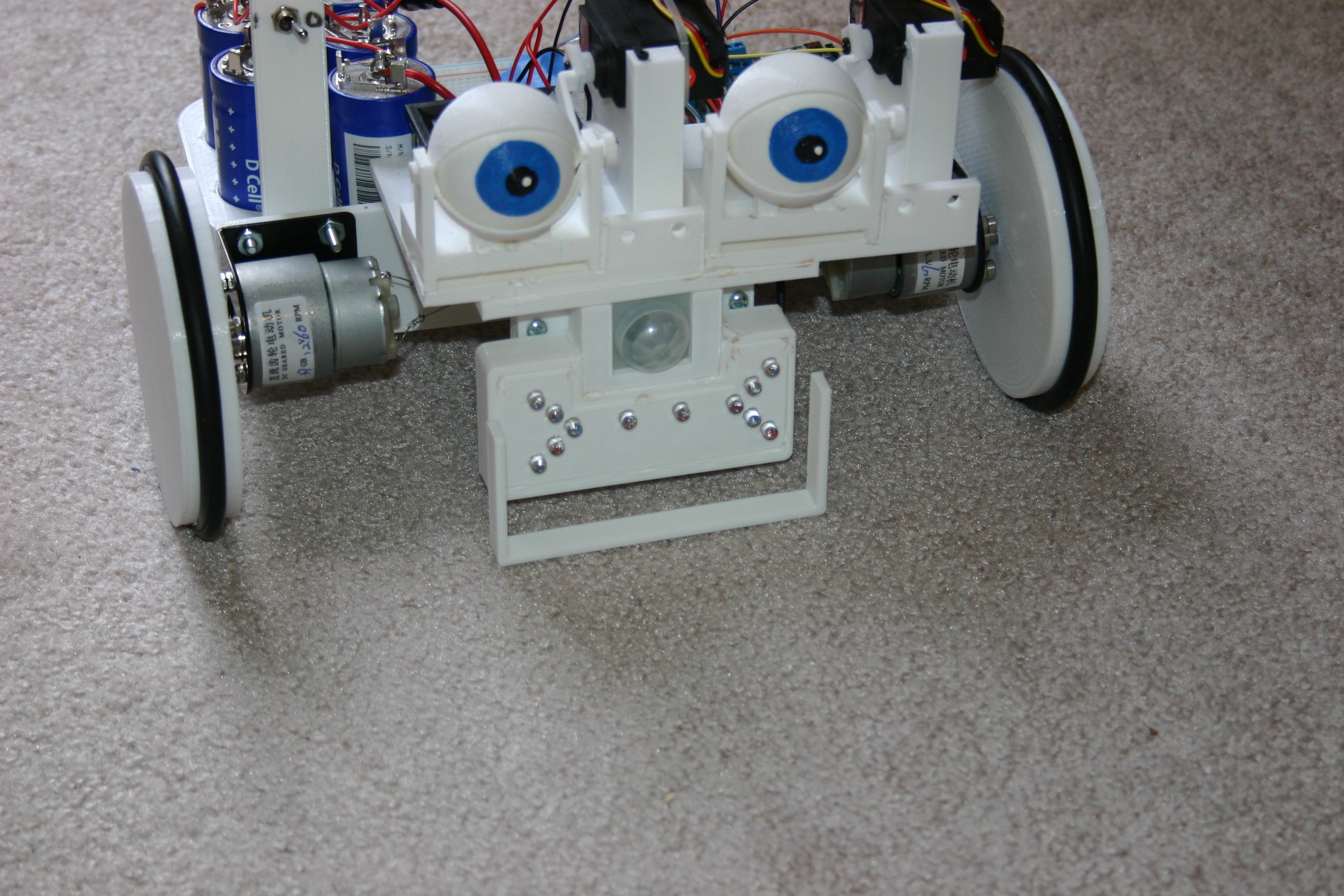
Using wire wrap wire, connect three groups of (4) leds—each group in parallel with a series resistor. The upper slanting 4, the middle “line” 4, and the lower slanting 4 are the groups.
![]()
Test the lights before gluing the case together.
![]()
Thread the wires over the top of the wide base into the Arduino area.
![]()
Glue or melt the “mouth” to the nose.
![]()
Install the wires to Arduino pins 0,1,2 and gnd.
![]()
Remove the sticky backing and put the breadboard in place.
![]()
Install (glue) bump guard onto mouth assembly.
![]()
Install transistor switch to control power to servo motors. These motors consume about 60 milliamps just staying in place—and that is too much drain on our limited supply.
![]()
Check the wiring according to this schematic.
![]()
The Arduino file, “Little friend smile” is posted on hackaday.io
Mato should run with a smile on her face that turns to a frown when she bumps into something. Occasionally, she will blink.If it has been a while since a “bump” occurs, she will half close her eyes for a few seconds of rest. If someone walks past (PIR active), she will smile, wink and move forward.
Mato will run until the capacitor voltage reaches about 3.5 volts, but I usually stop for a recharge at 4 volts. Using a bench power supply, set the voltage for 12.8 volts and the amps for 4.5 (my supply is only good for 5 amps—more amps would charge faster).
![]()
-
Bad Robot Parenting
04/23/2016 at 16:15 • 2 comments"Little Friend" was running around getting exercise (I was clocking run time with specific electrical load) when I exercised bad judgment as a parent.
"Little Friend" was at least 50 feet away from the stairs--around a couple of corners. I turned my back to work on gluing pieces of a project. It took less than a minute.
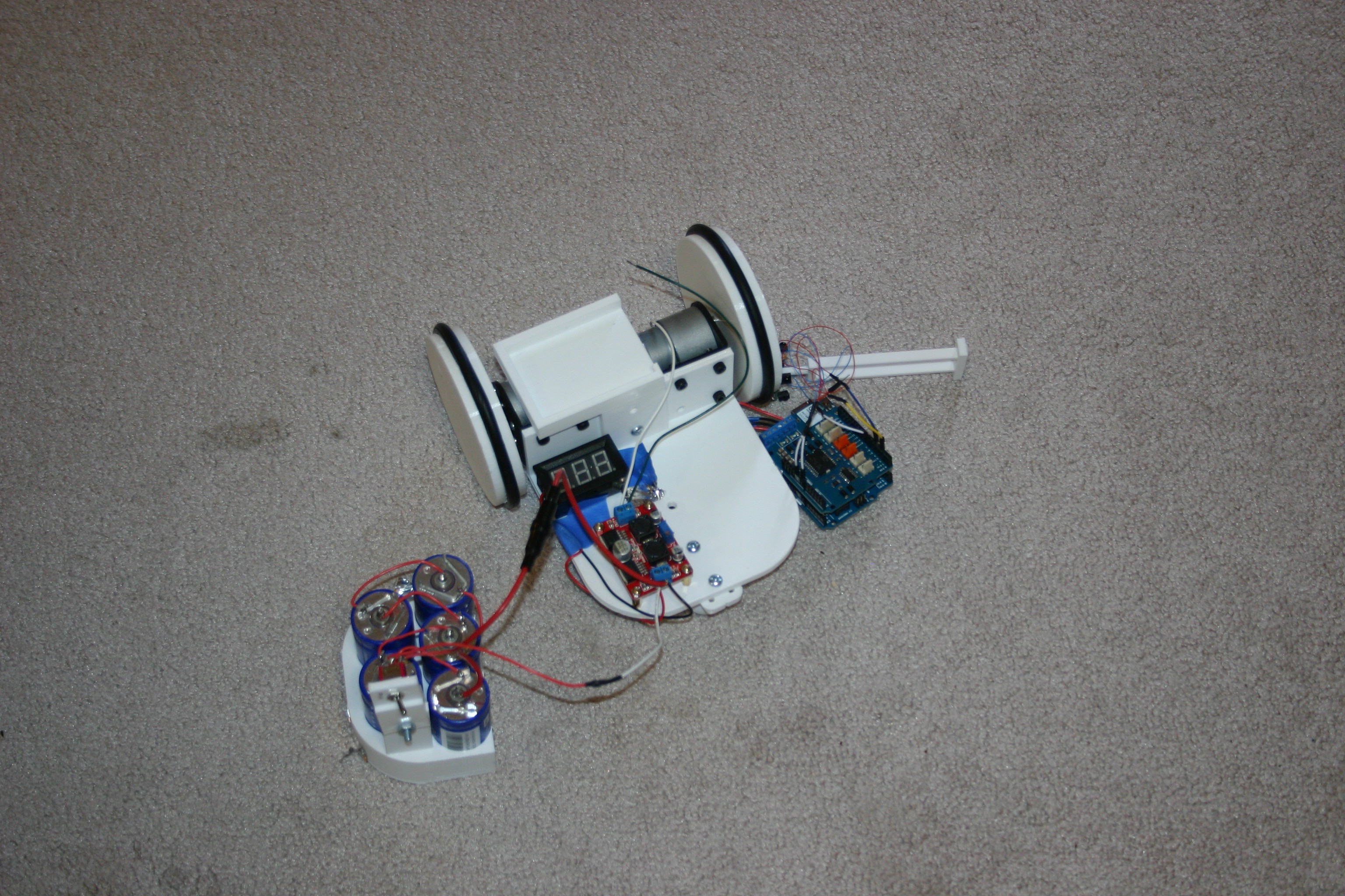
BANG, THUD, THUD, THUD, CRASH !!!
![]()
"Little Friend" took the shortest route to the stairs.
One of the wheels no longer runs true--will have to be replaced. Fortunately, there were no short circuits or broken circuit boards.
NEVER let a little one out of your sight unless dangerous spots are adequately secured.
Little Friend
This companion robot, 9000 farads of super capacitance, spends less than eight minutes feeding--then 75 minutes or more she can be a buddy.