Dillon Nichols
-
The Hardware Story (Part 2: Suck It Up)
08/17/2016 at 15:35 • 0 commentsAfter the many hours that went into the initial hardware design, it became clear there was more work to be done. What followed was several weeks of contemplation, reflection, and mourning, but then it was time to suck it up and try again with a new approach: a vacuum system. (pun intended if you couldn't tell.. I'm guessing you could tell... I hope you could tell....)
The vacuum idea was different than most drink machines I've seen others make. It would address the problems from our initial design, but there were new challenges that needed to be addressed, mainly with how to plumb the system. Keeping in mind goals for the system to be reasonably low-cost, and simple, yet functional and compact led to the following design:
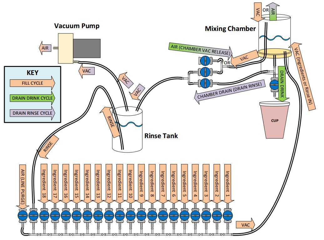
![]() To pour a drink, there are essentially 4 steps, using 3 different flows or "cycles". These cycles are identified in the diagram as the "Fill Cycle", "Drain Drink Cycle", and "Drain Rinse Cycle". The different cycles represent different states of the blue solenoid valves, creating different flows in the system. To elaborate, let me walk you through a complete drink pouring process.
To pour a drink, there are essentially 4 steps, using 3 different flows or "cycles". These cycles are identified in the diagram as the "Fill Cycle", "Drain Drink Cycle", and "Drain Rinse Cycle". The different cycles represent different states of the blue solenoid valves, creating different flows in the system. To elaborate, let me walk you through a complete drink pouring process.Step 1a: (Fill Cycle)
In the Fill Cycle, arrows having a light orange color indicate the flow. (Arrows with two colors apply to two different cycles.) To start the process, the vacuum pump turns on, and the valve connected between the rinse tank and the hose extending to the top of the mixing chamber opens. This creates a vacuum inside the mixing chamber. Notice that the vacuum hoses from and to the rinse tank do not extend down into the rinse solution. The rinse tank is a solid sealed container, so the vacuum created in the rinse container is also created in the mixing chamber. With the vacuum established, the individual ingredient valves can be opened to bring the ingredient from the bottle into the mixing chamber. The ingredient valves are opened one at a time, and timed according to a calibration factor to retrieve the appropriate amount.
Step 1b: (Line Purge)
After the ingredients have been sucked into the mixing chamber, there is still some liquid remaining in the line. To make sure it is included in the mix, the line is purged by opening the AIR (Line Purge) valve at the end of the ingredients valve array. A side-effect of this is that the air purging the line bubbles up through the mixture in the mixing chamber, effectively mixing the ingredients. Once the line is purged, the valves are closed and the vacuum pump is shut off.
Step 2: (Drain Drink Cycle)
The Drain Drink Cycle is fairly simple. In this cycle, the DRAIN DRINK valve opens at the bottom of the mixing chamber, and the AIR (Chamber Vac Release) valve opens, releasing the vacuum in the chamber and allowing the mixed solution to dispense into a cup. After a timed amount, the valves then close.
Step 3: (Rinse - Fill Cycle)
At this point, the consumer is happy and has left the drink machine. You might be thinking... "Like, ewww now the next person will get any leftover liquid in the mixing chamber contaminating their drink." This is a downfall to this vacuum system approach. The solution, is the rinse cycle. This step is the same as Step 1, but instead of ingredient valves opening, only the RINSE valve, second to last in the ingredient valve array, will open. This will flush the line and fill up the chamber. Then, the line will again purge like in Step 1b, and the air-bubbles will help agitate the rinse in the mixing chamber.
Step 4: (Drain Rinse Cycle)
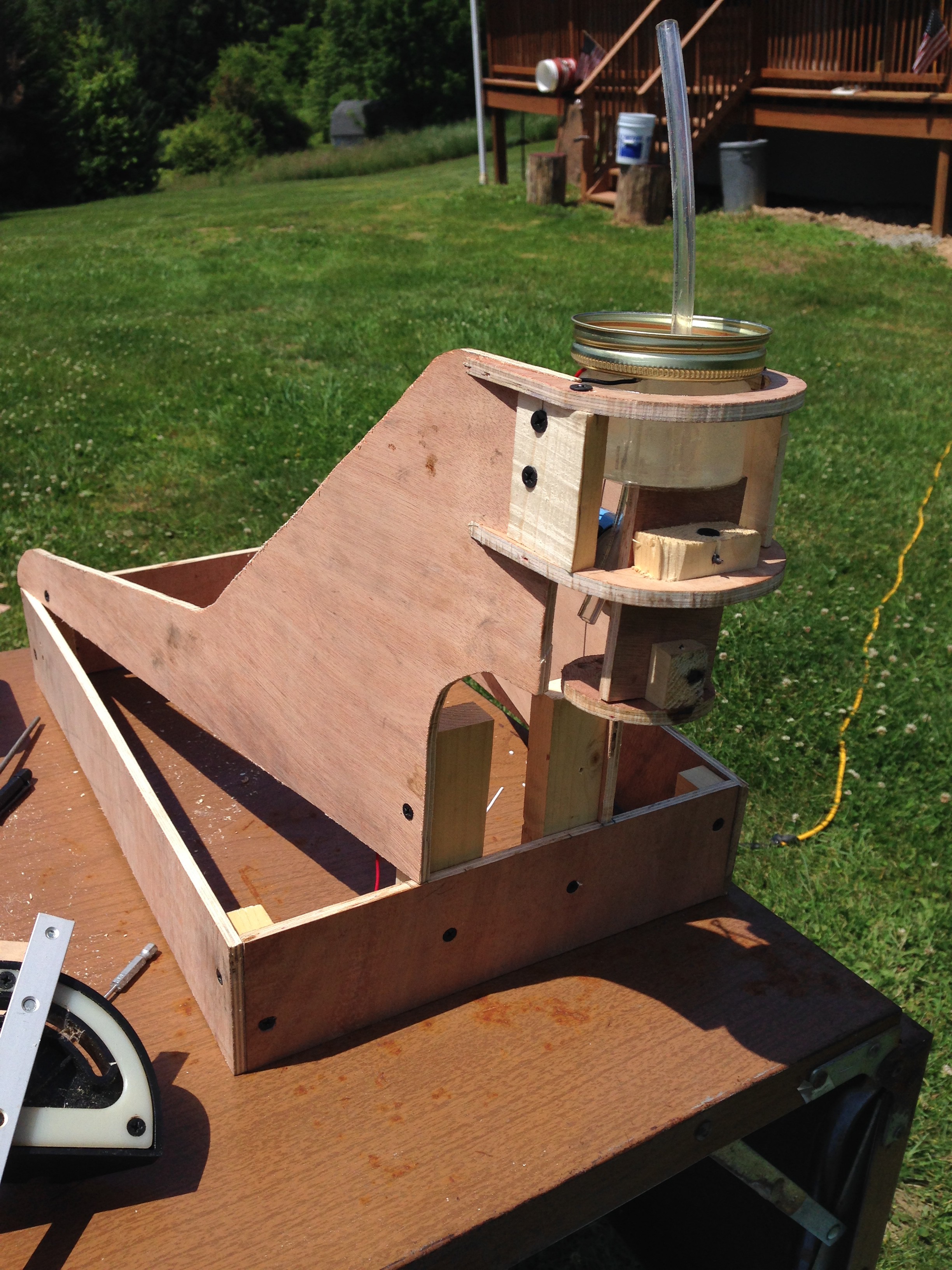
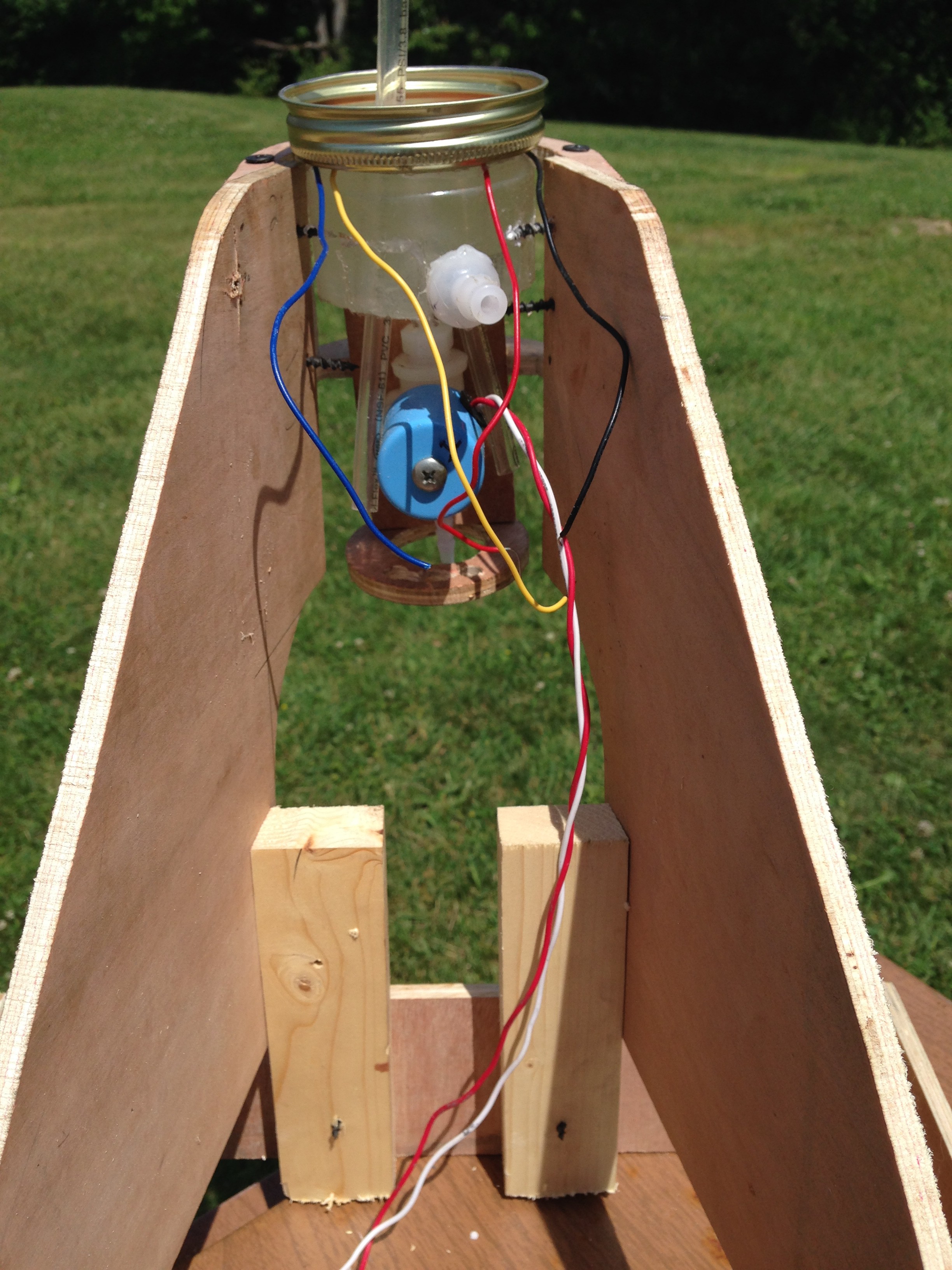
Finally, the last thing to do is empty the rinse solution from the mixing chamber, but we don't want to simply spit this stuff out of the drink faucet! In the Drain Rinse Cycle, the vacuum pump activates, but instead of the vacuum being routed to the top of the mixing chamber, the CHAMBER DRAIN (DRAIN RINSE) valve opens, along with the AIR (CHAMBER VAC RELEASE) valve. In this way, the rinse solution in the mixing chamber is vacuumed back into the rinse chamber for re-use. Now, obviously there may still be some drops of rinse solution that remain in the chamber, but this seems to be more acceptable than a sticky, strong tasting liquid. If water is the rinse solution, then the drink would be less contaminated than the effect from adding ice. It should also be noted that the mixing chamber is an easily removable container (in our case a Mason jar) for further periodic cleaning. The rinse tank is also removable so that the solution can be renewed. Now that we've talked about the plumbing system, let's look at what's controlling all of this.
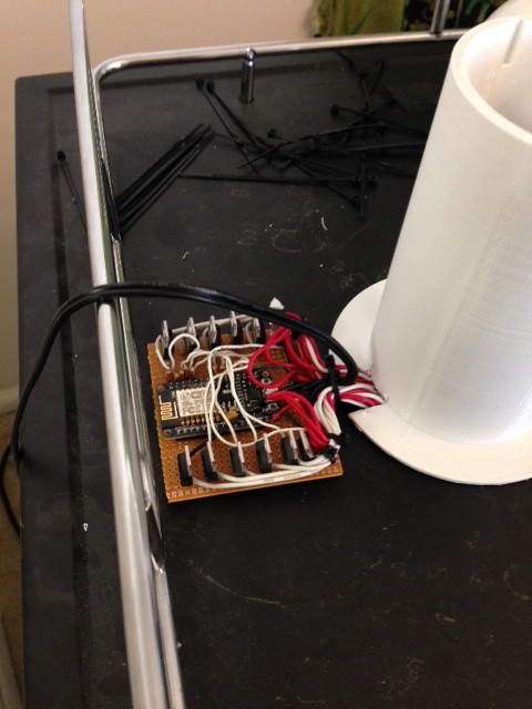
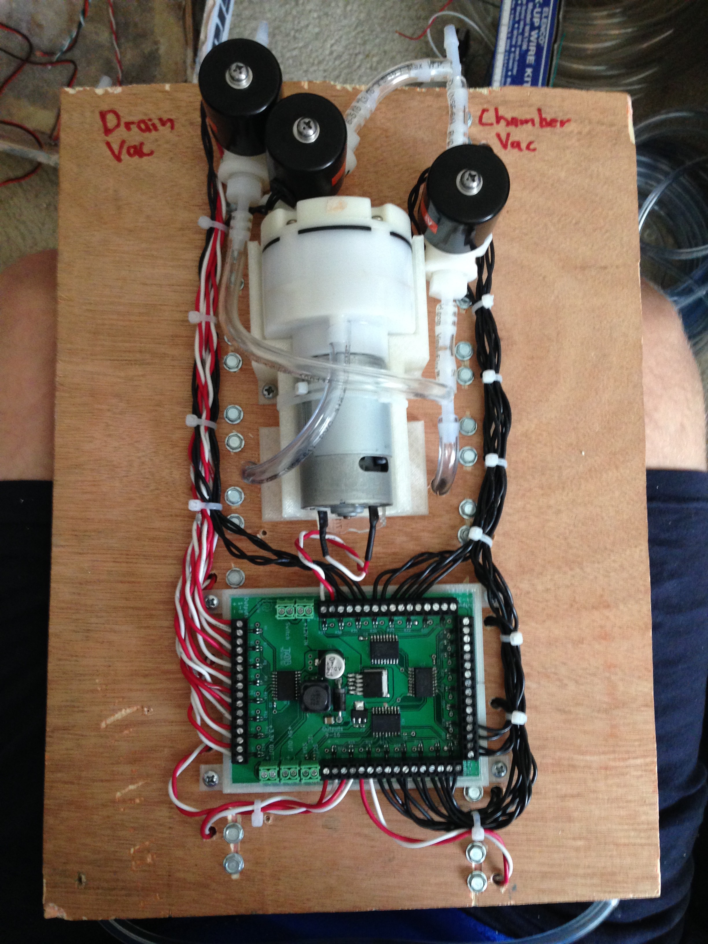
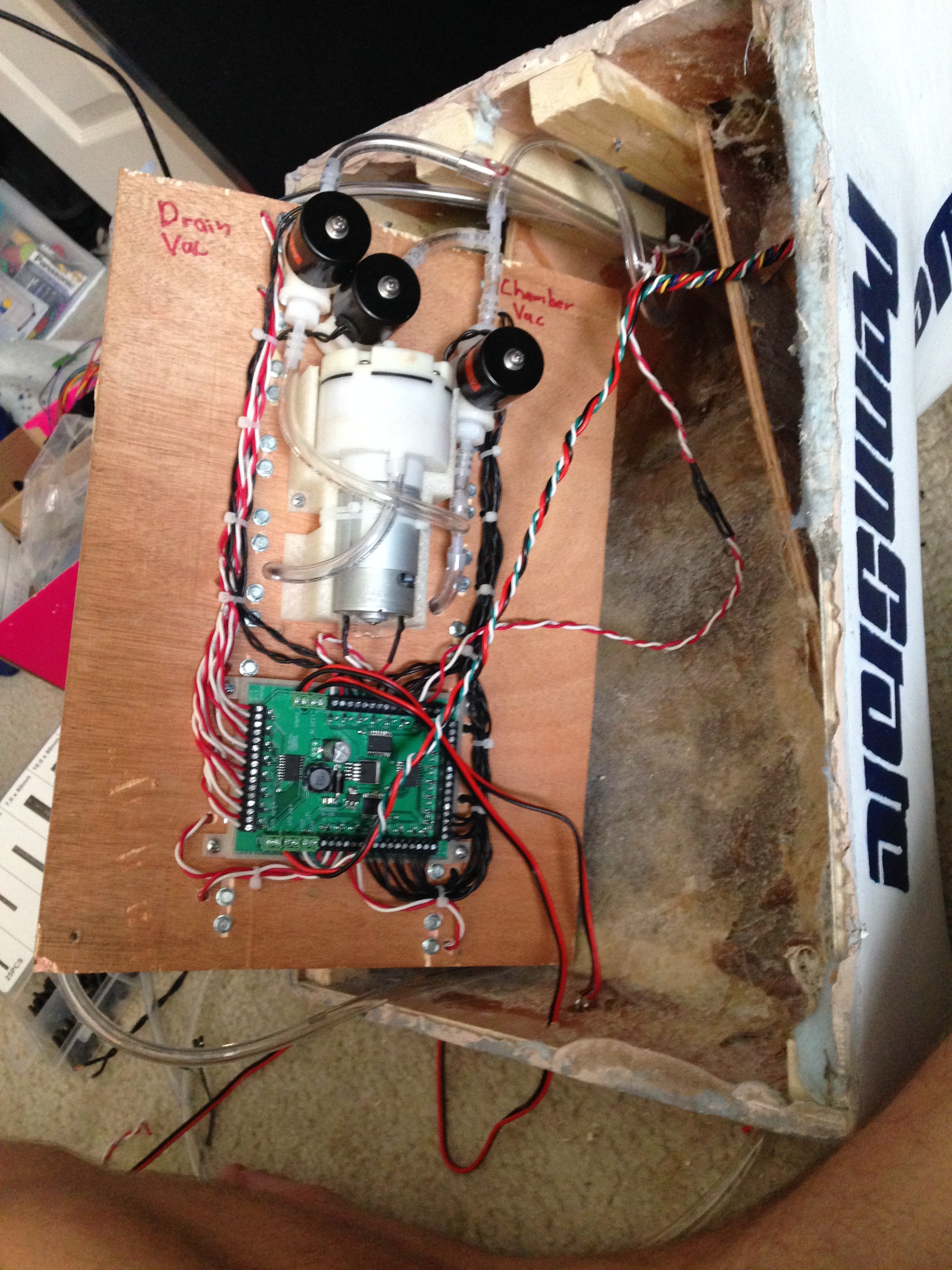
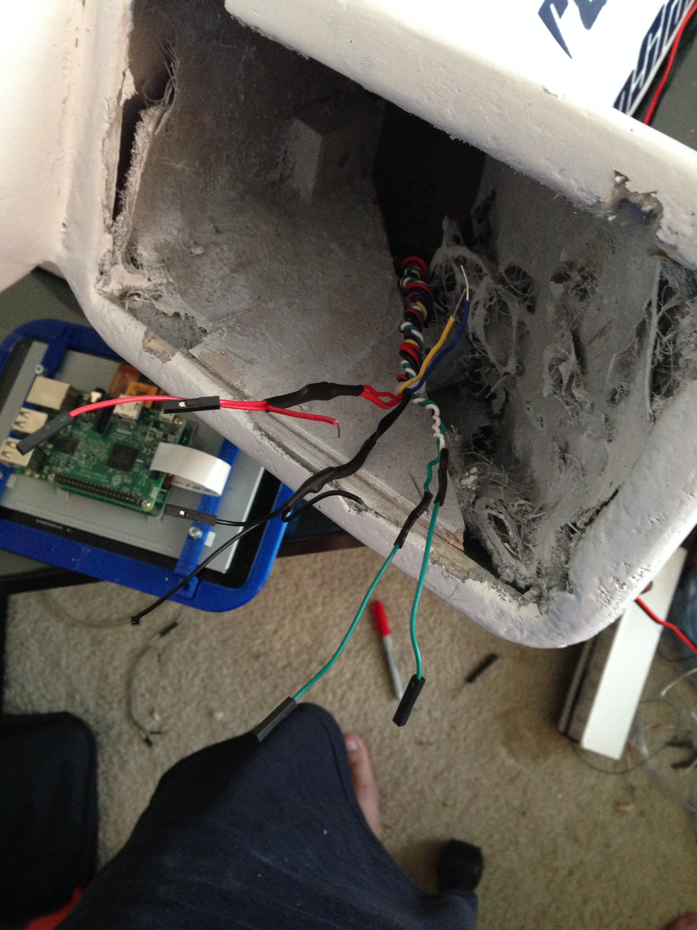
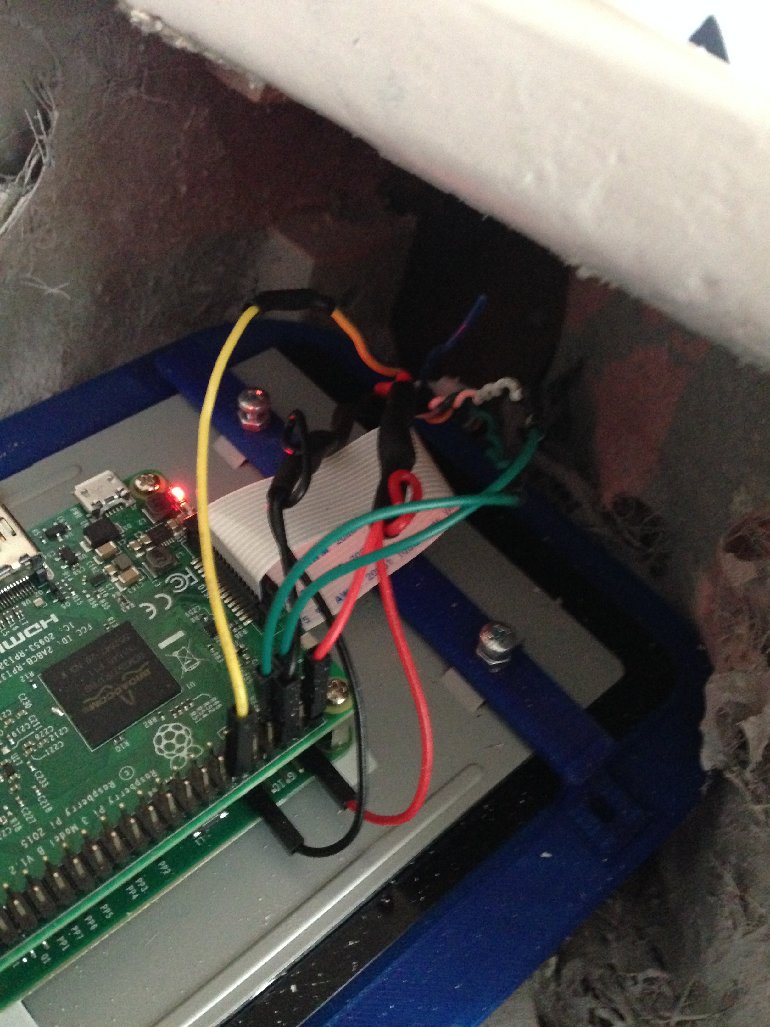
Since we wanted this to be a community project, we wanted to try and use familiar hardware. To have a capable system with several valves for ingredients, it was also necessary to have many GPIO. The best solution we came up with was to implement the GUI software and hardware control software on a Raspberry Pi 3. The Raspberry Pi 3 was paired with the standard Raspberry Pi 7" touchscreen to provide the user interface. To connect the valves and pump, we developed our own PCB utilizing MCP23008 I2C GPIO expanders connected to some Power MOSFETs. This PCB is powered by 12V for the pump and valves, but also provides a switching power regulator to provide 5V to the Pi. The schematic and Gerber files for this board can be found on the project GitHub page at https://github.com/theopenbar/PCB. The design was generated using KiCad. On GitHub, you will also find the Python hardware control program for the Raspberry Pi 3 at https://github.com/theopenbar/Controller.
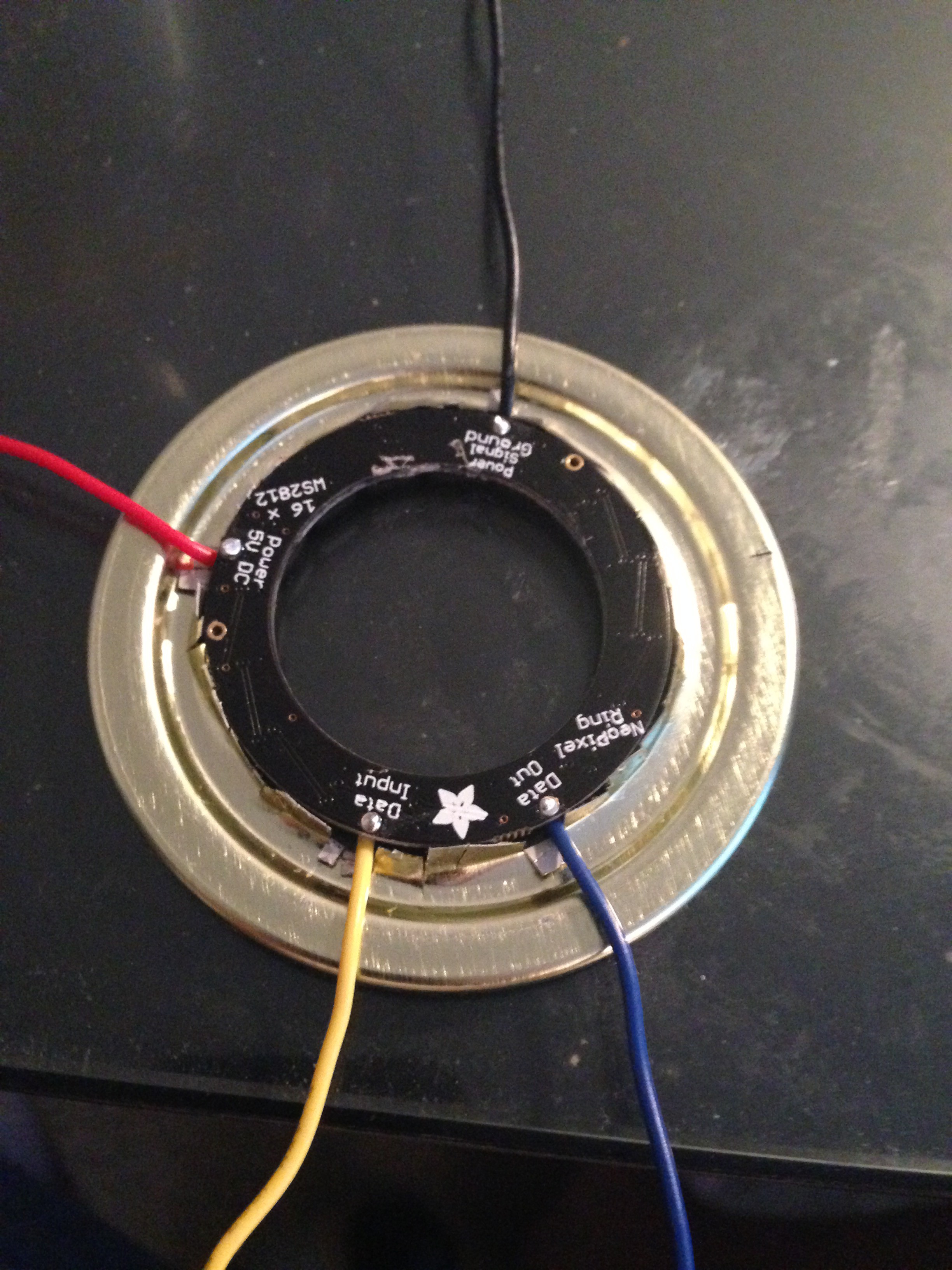
Another (optional) hardware piece we added to the system was a NeoPixel LED ring. These can be found on Adafruit here: https://www.adafruit.com/products/1463. We implemented the ring into the mixing chamber for some cool lighting effects during operation. Here is a simple wiring diagram of the system:
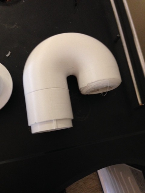
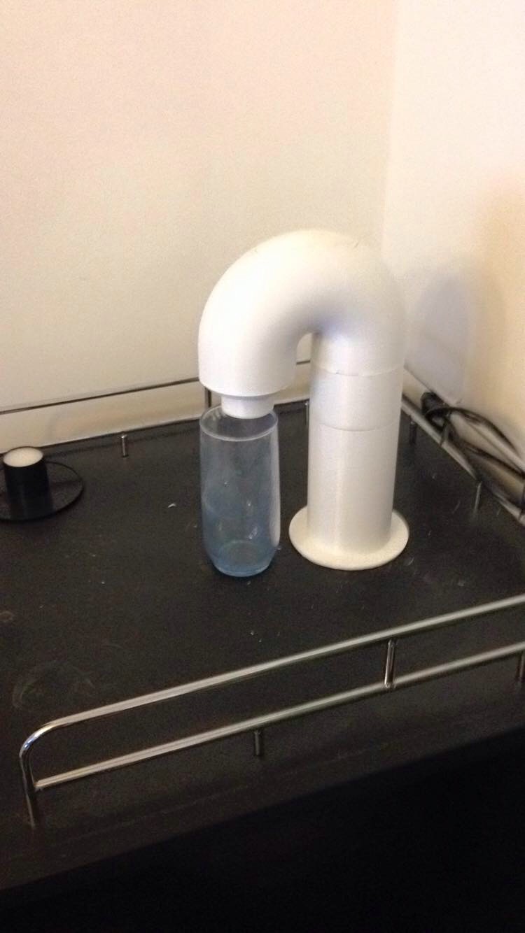
For the actual structure of The Open Bar, this is one area where we left lots of room for creativity. For our approach, we wanted to create a compact all-in-one "set-top box". The idea was that if the unit is small, compact, and contained, it could be mounted on top of a kegerator, mini-fridge, or even a cooler for tailgating or camping. The necessary modification would be routing the individual ingredient and rinse tank hoses inside the device housing the bottles. Most likely, this means cutting a hole in the top.![]()
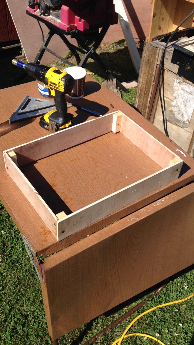
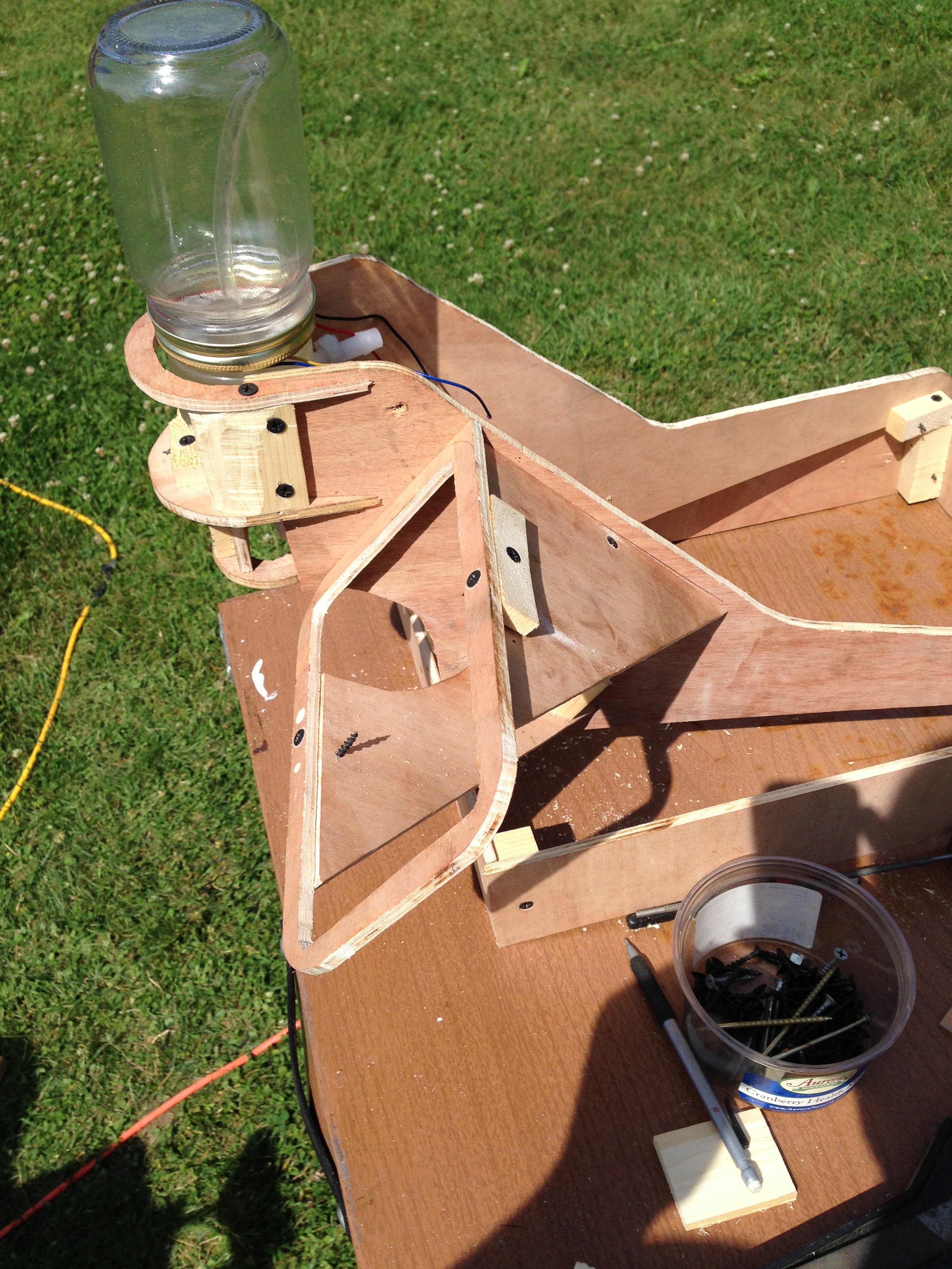
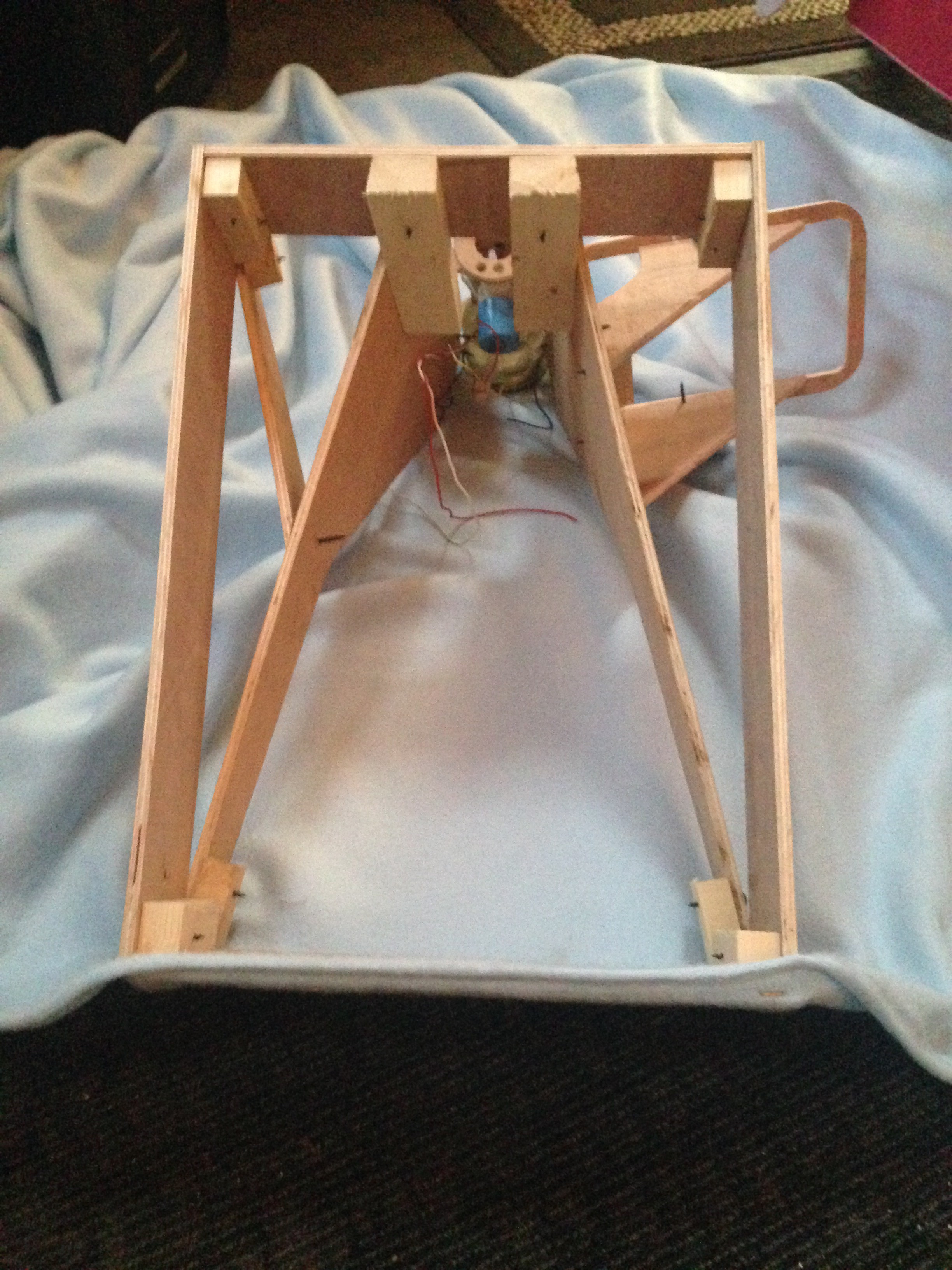
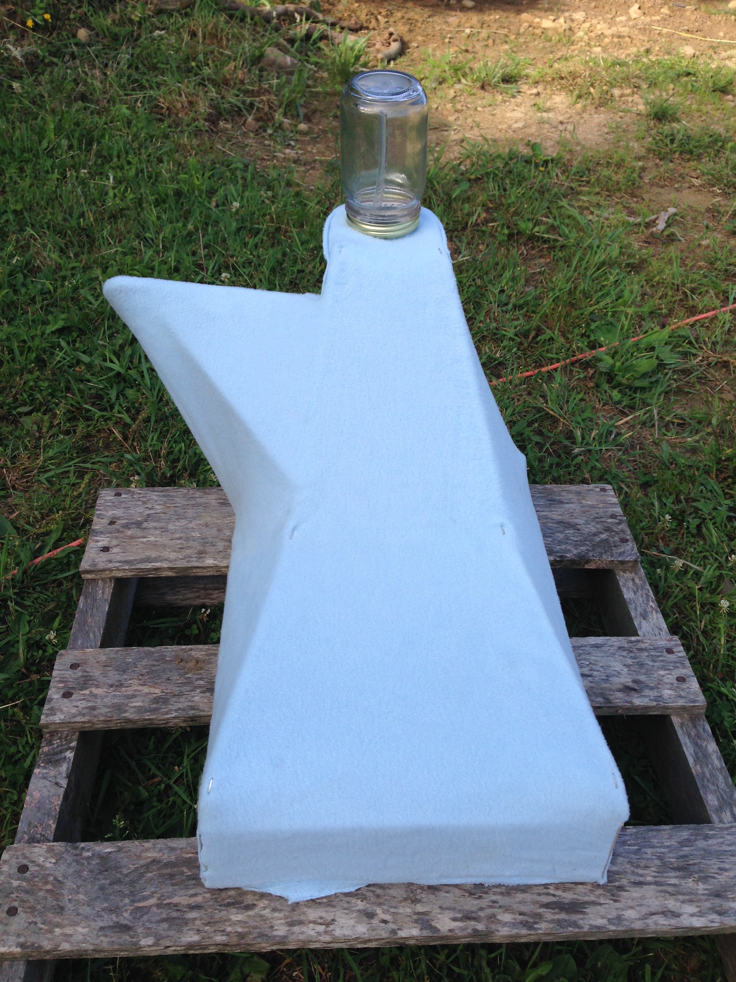
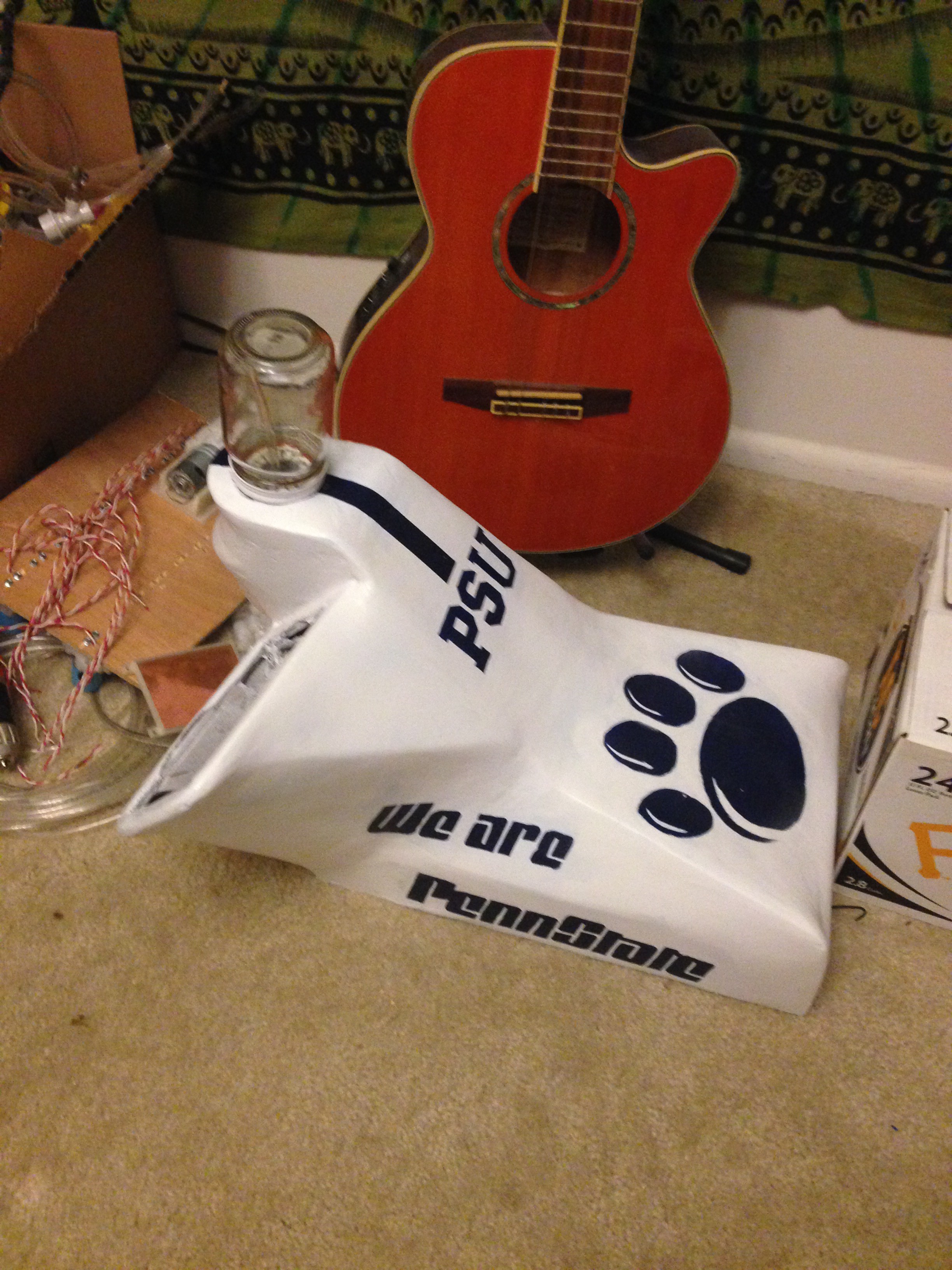
After watching some YouTube videos on people making various things from fiberglass, like boats and custom sub-woofer enclosures, I really wanted to try my hand at fiber-glassing. So for my implementation of The Open Bar, this is the route I took. Eventually, we're going to make detailed videos of a complete build, hopefully with a complete BOM and measurements. For now, here's a brief pictorial of my work constructing The Open Bar. This build was to prove the concept and sort out any bugs:
![]()
![]()
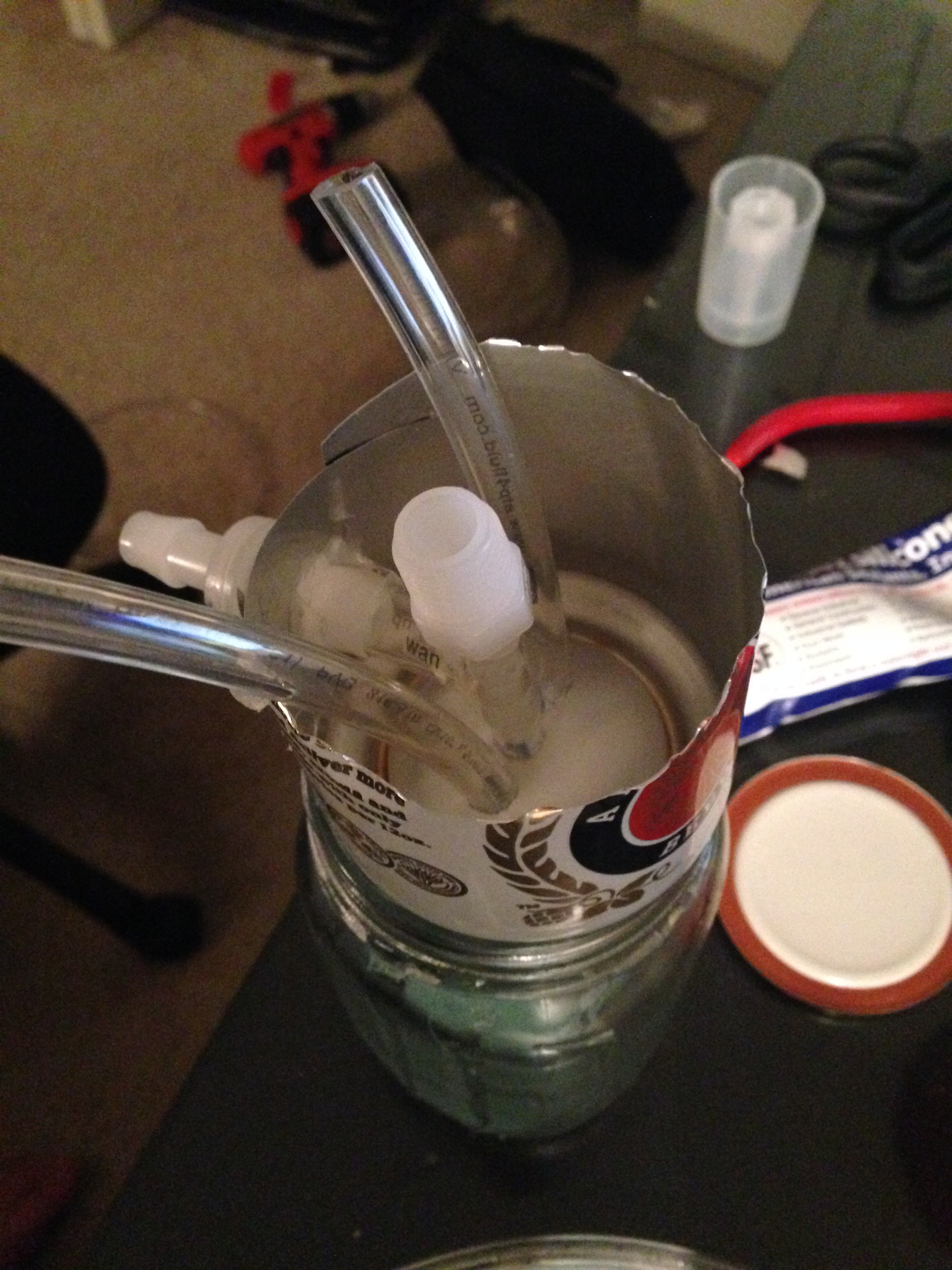
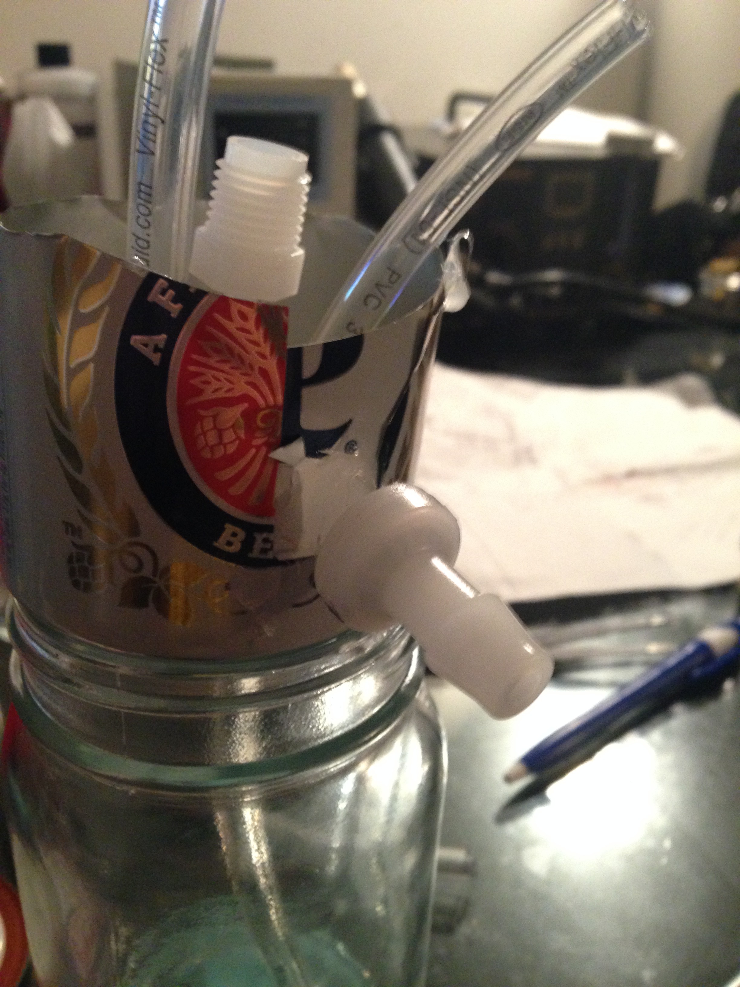
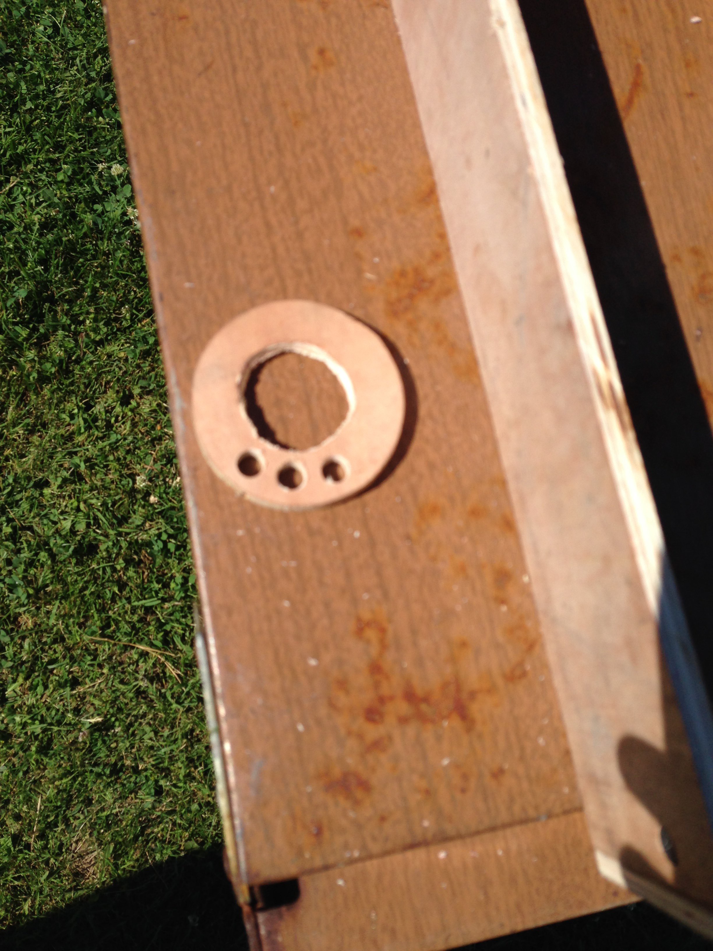
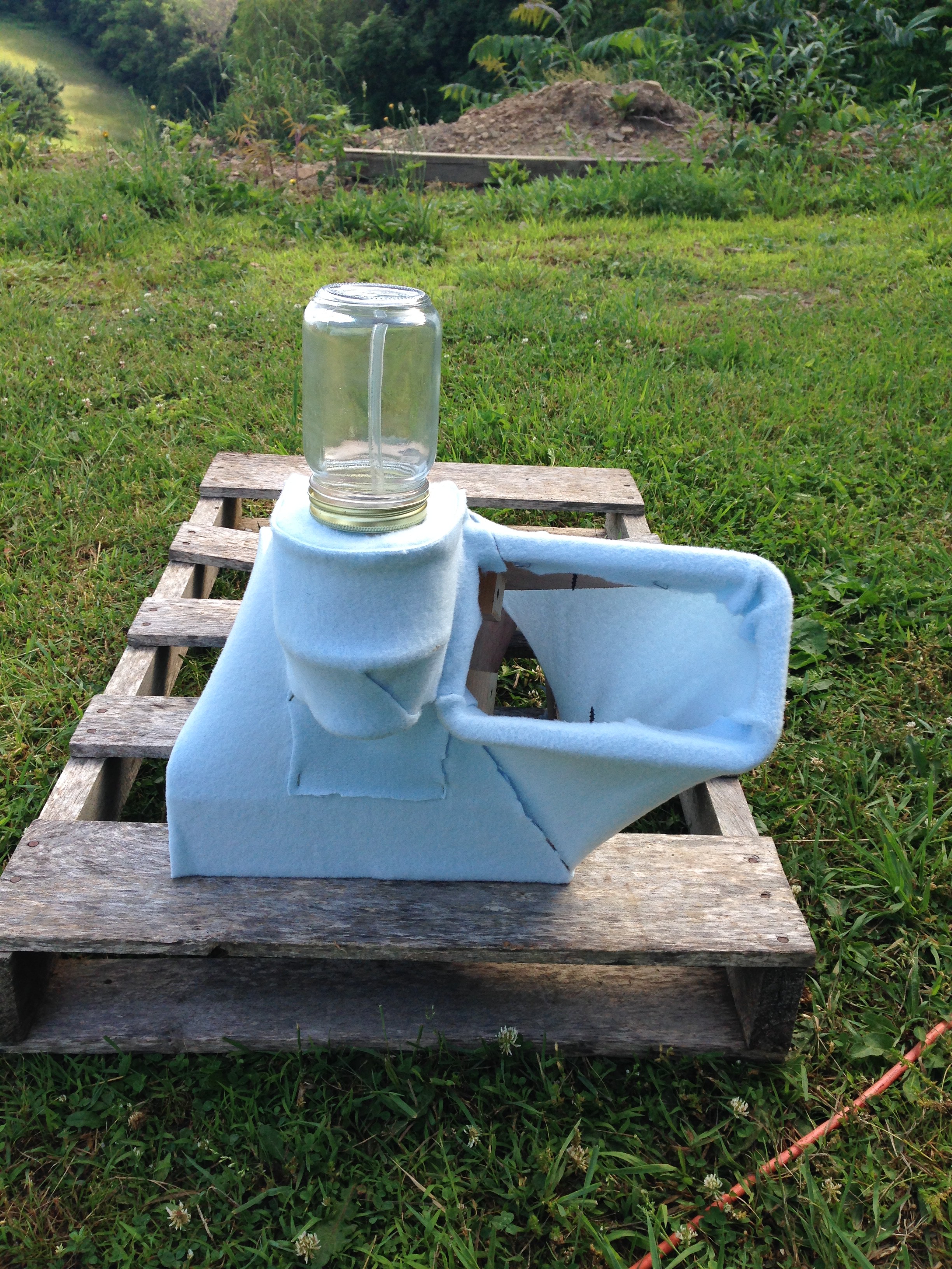
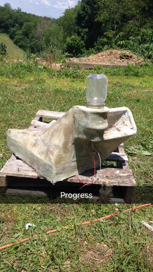
This is molding the first part of the mixing chamber base. It was molded inside an aluminum can with a hard-setting food-safe acrylic. It is upside-down in the above and below picture. The slight bowl in the bottom of the can will help to drain the chamber to the center drain hole. The drain valve will attach to the center NPT fitting. The two hoses are for the incoming ingredients and the vacuum connection. The other plastic fitting going out the side is a check-valve on the connection to drain rinse from the chamber. In the finalized design I decided to use a valve there instead. The Mason jar is just used as a support here.
![]()
![]()
![]()
![]()
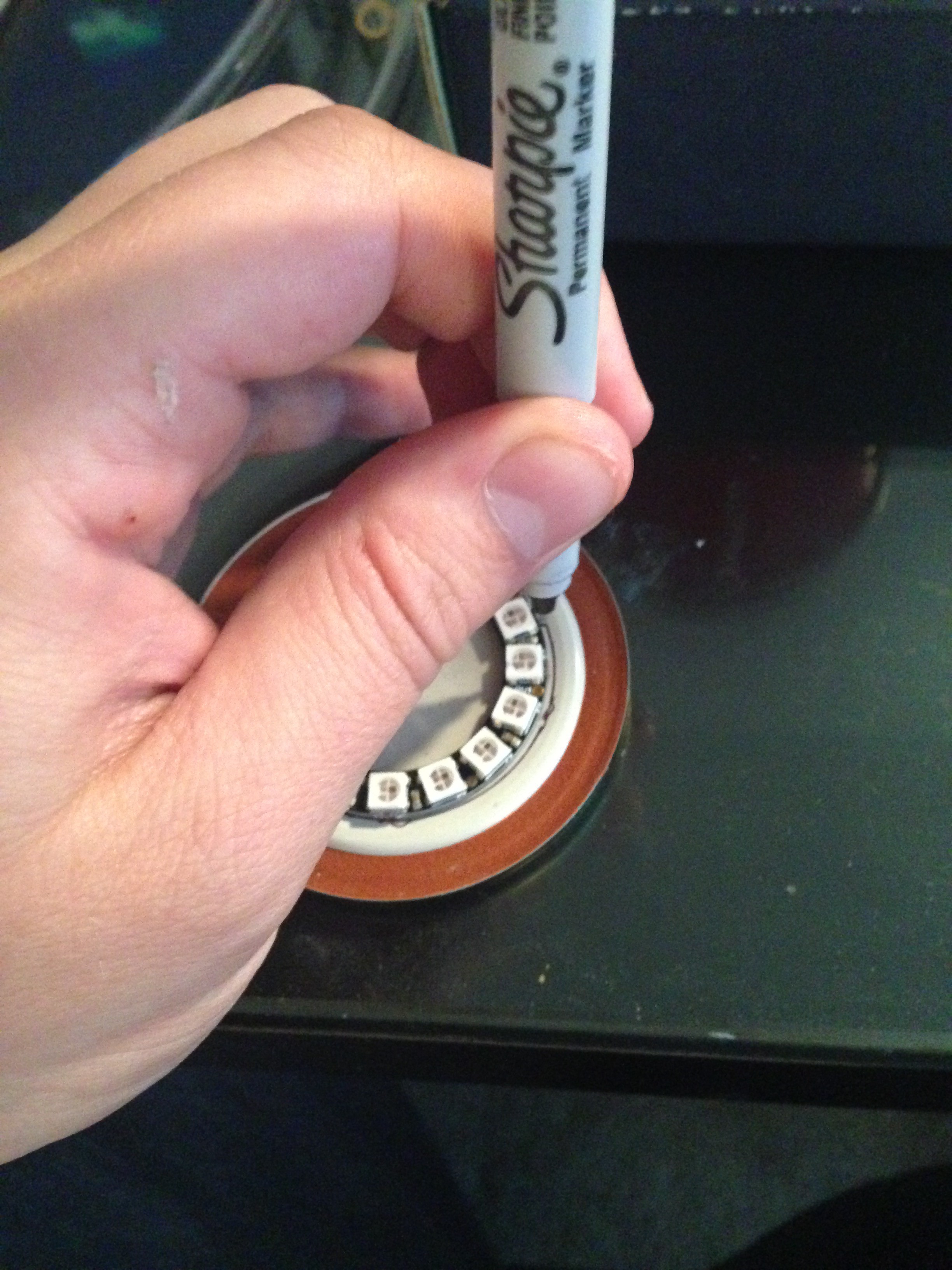
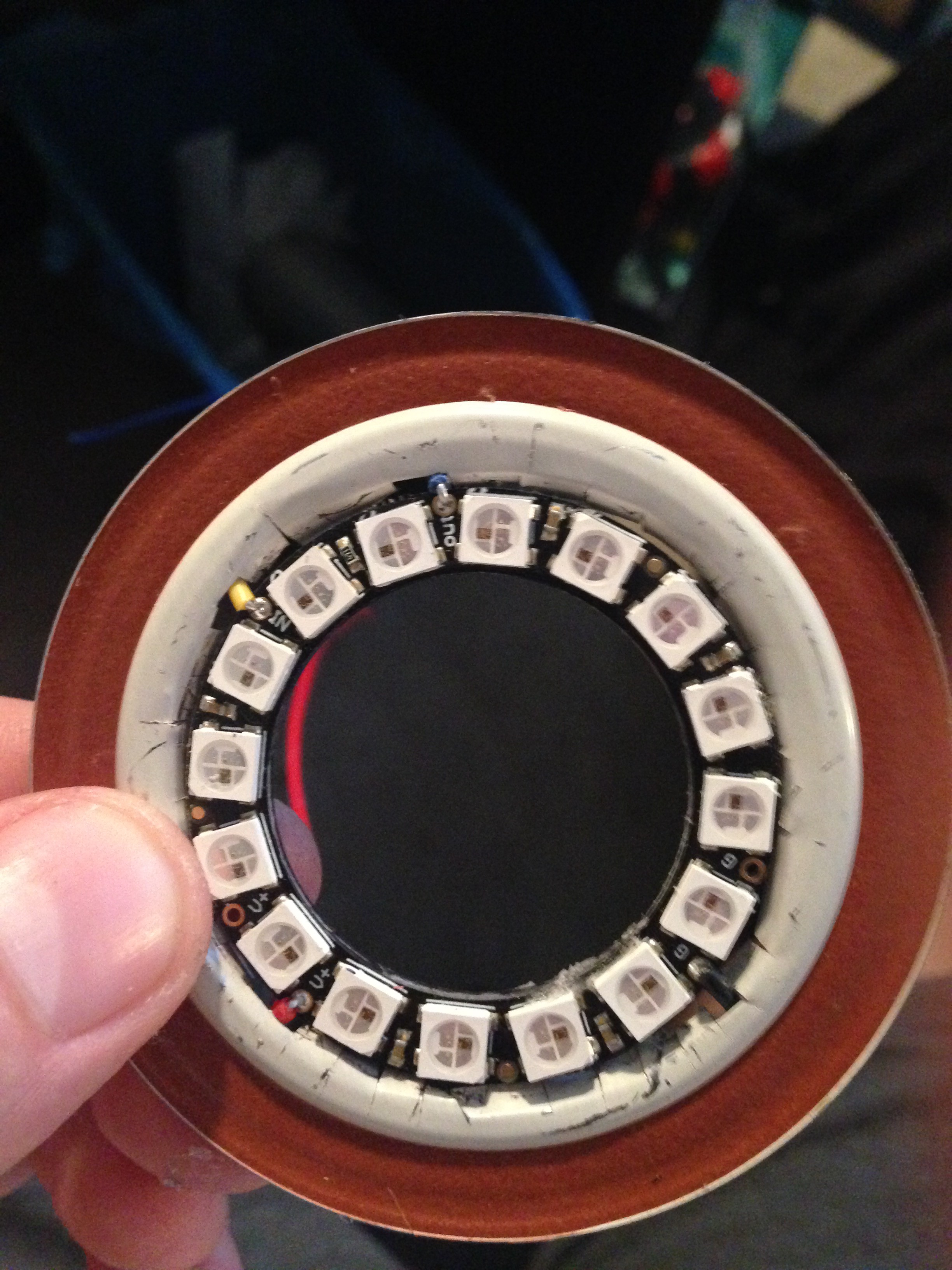
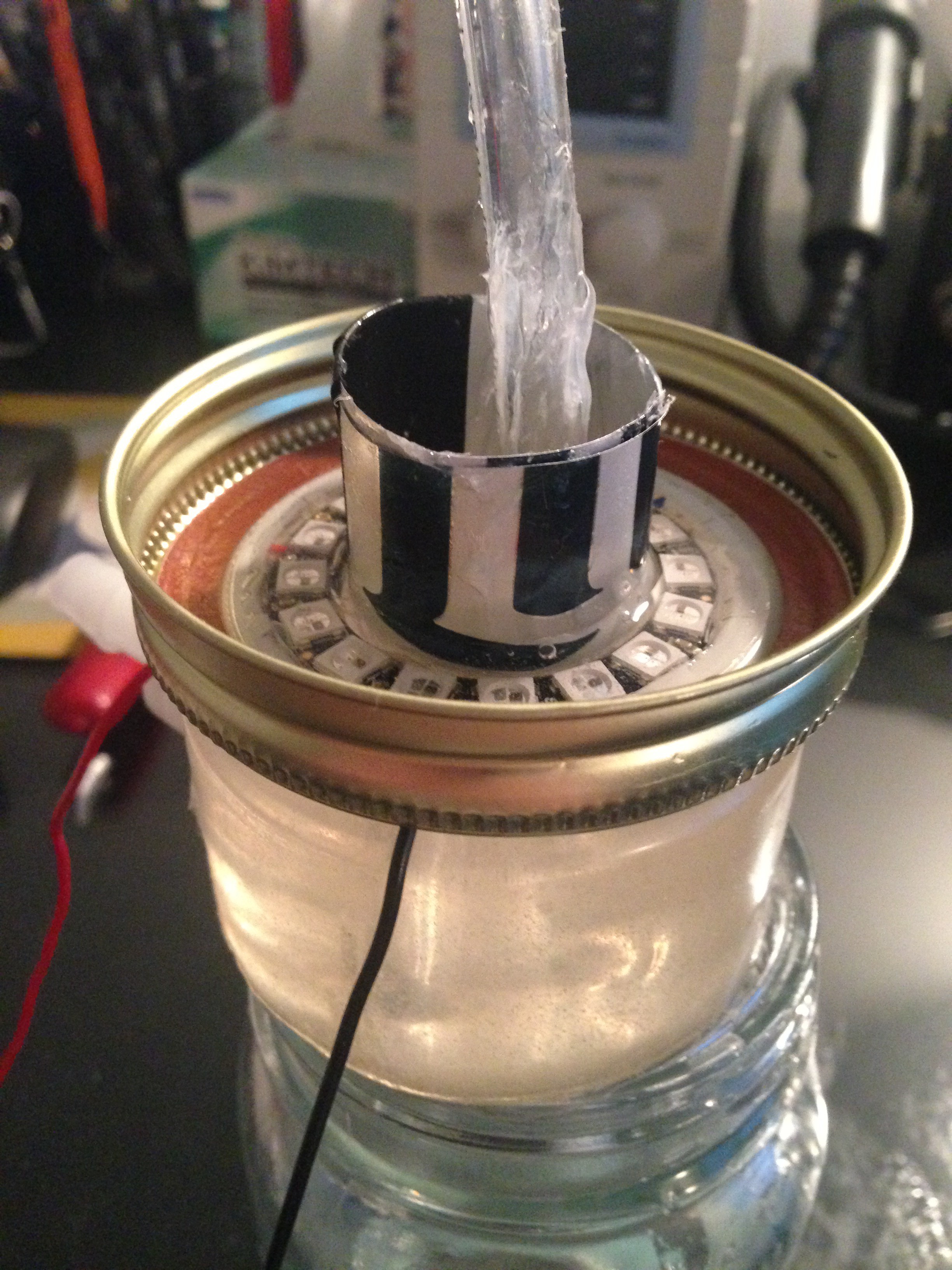
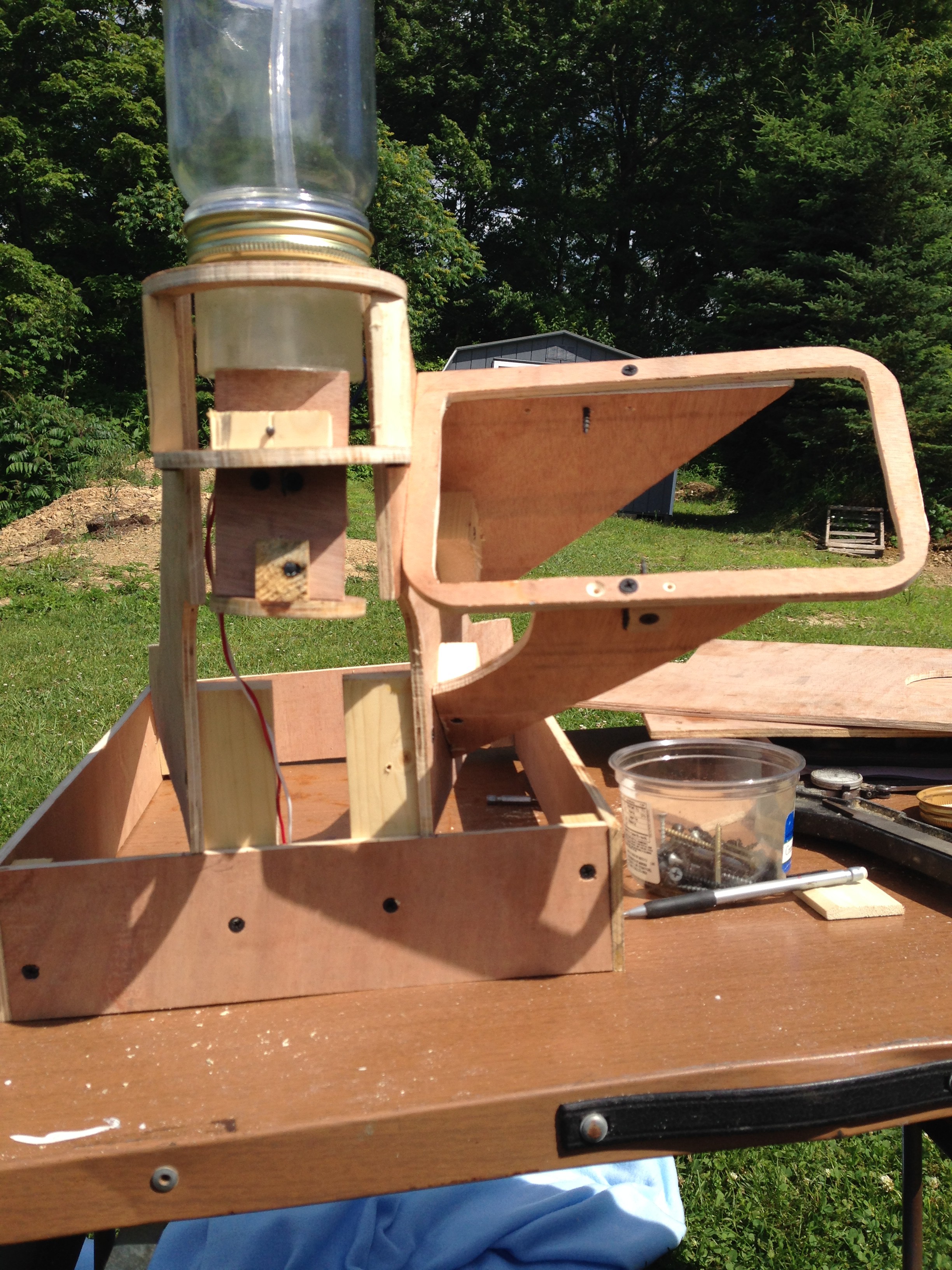
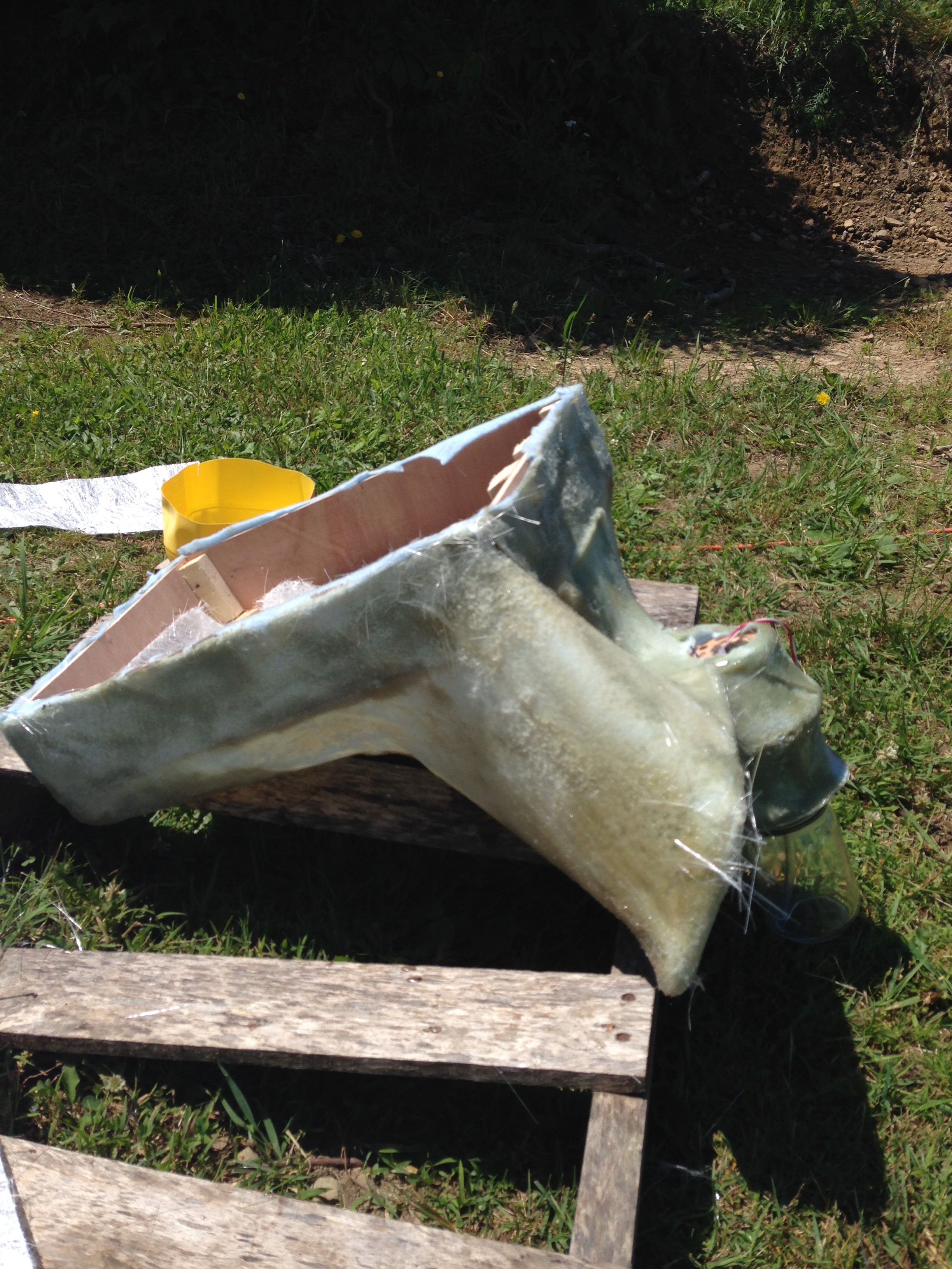
The NeoPixel Ring was placed inside a Mason jar lid. Food-safe silicon was placed around the lid and then set on top of the previous formed mixing chamber base. Then as show below, a cylinder formed from another piece of aluminum can was placed within the ring. The bottom of the cylinder had silicon around it to seal the base. This is to form a cylindrical riser from the bowl formed by the bottom of the aluminum can. I then poured more food-safe acrylic over the NeoPixel Ring to seal it and form it to the first part of the mixing chamber base. (Sorry I don't have more pictures of this. When we make another machine, we will make videos and be as detailed as possible.)
![]()
![]()
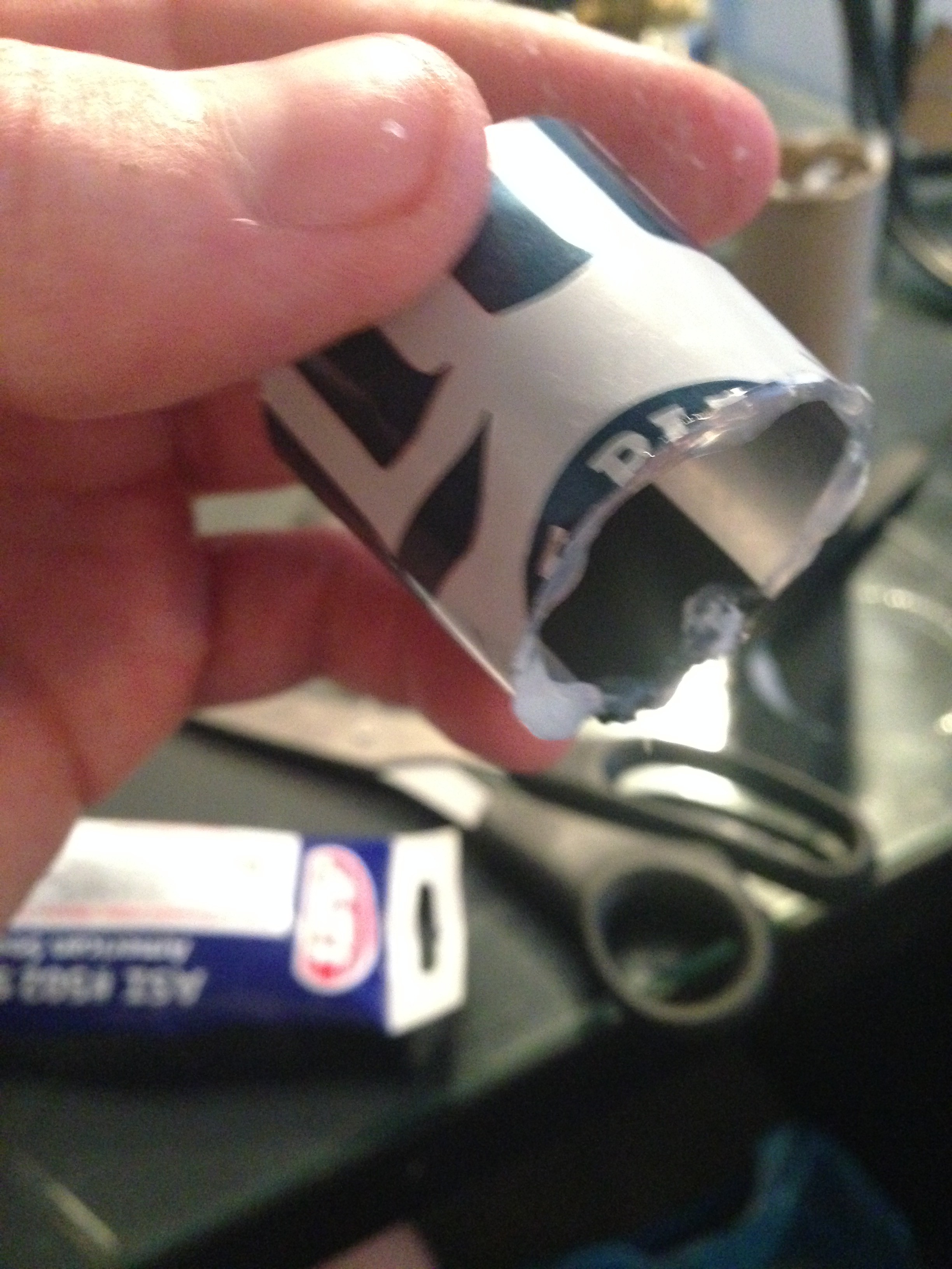
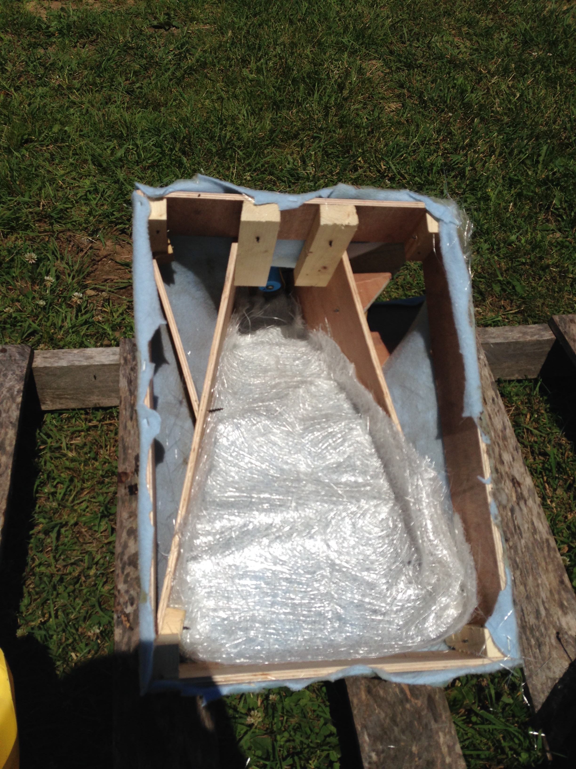
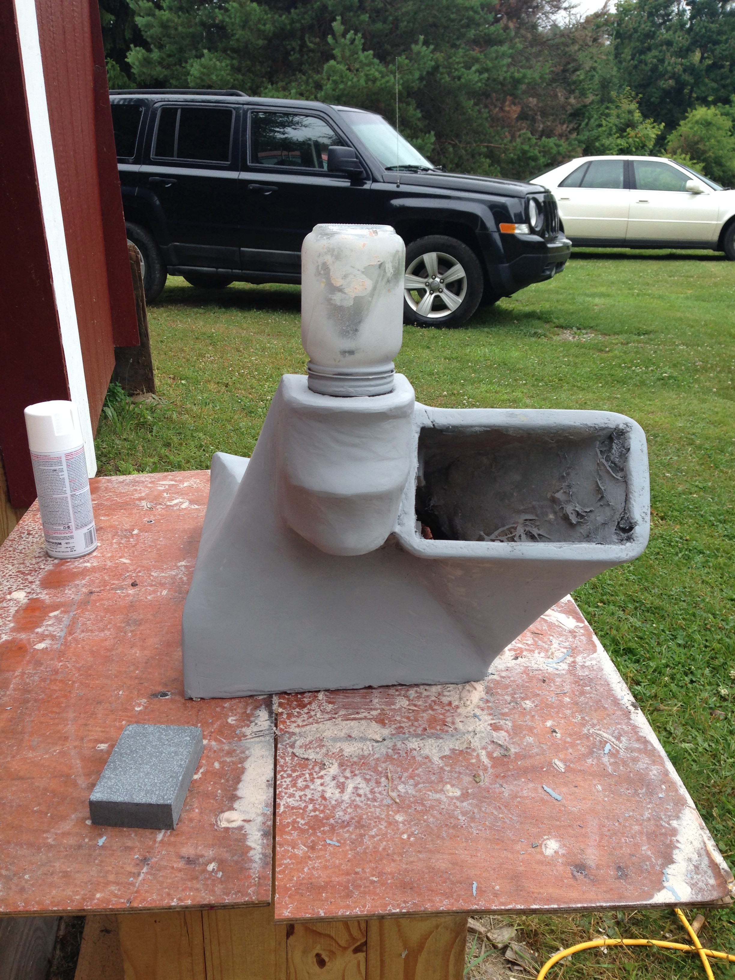
The above picture show the second part of the mixing chamber base consisting of the Mason jar lid, being formed on top of the first acrylic part. The clear food-safe acrylic covers the NeoPixel Ring from the inside part of the red rubber seal of the Mason jar lid, and the space in-between the aluminum cylinder and underneath the NeoPixel Ring. After the acrylic sets, the aluminum cylinder is removed, revealing a cylindrical cavity joined to the bowl shape of the first (bottom) piece of the mixing chamber base. The hose inside the cylinder is the vacuum hose that extends to the top of the mixing chamber. Again the Mason jar is just for support here.
![]()
![]()
![]()
![]()
![]()
![]()
![]()
![]()
![]()
![]()
![]()
![]()
![]()
![]()
![]()
![]()
![]()
![]()
![]()
![]()
![]()
![]()
![]()
![]() I tried to minimize 3D printed components so that they weren't necessary. I did cheat a little, but this just leaves some room for others to contribute ideas and get creative. For those that attempt this and do have a 3D printer accessible, I posted my 3D files on Thingiverse here: http://www.thingiverse.com/tylerh127/designs.
I tried to minimize 3D printed components so that they weren't necessary. I did cheat a little, but this just leaves some room for others to contribute ideas and get creative. For those that attempt this and do have a 3D printer accessible, I posted my 3D files on Thingiverse here: http://www.thingiverse.com/tylerh127/designs. -
The Hardware Story (Part 1: Fail)
08/08/2016 at 18:53 • 0 commentsFor The Open Bar hardware design, we started off with a simple approach. For the first iteration of the project, the idea was to use a CO2 tank to pressurize the ingredients that would be dispensed. Each one of the ingredients would have 2 hoses -- a pressurized hose from the CO2 tank regulator going in, and a hose from the bottom of the bottle going out to a solenoid valve. From the valve, another hose would go to the faucet of the drink machine. In this way, each ingredient would have a separate path, and to add more ingredients you just needed to add a valve and hose.
To control the valves, we tried using a cheap ESP8266 wifi module. In our application, the ESP module implemented a simple HTML server. The user GUI, implemented on another device in a web browser, would send a HTML "GET" request, passing a GPIO number and a number of milliseconds as parameters. The ESP module would then activate the specified GPIO for that amount of time. Each GPIO was connected to a TIP120 NPN Power Darlington Transistor through a resistor. The transistors provided open-drain current sinks, acting as switches for the solenoid valves. The valves were powered by a 12V rail supplied by an AC/DC power adapter.
Although the ESP worked as a controller, there were several limitations. One limitation was the number of GPIOs available. There were about 10 usable GPIOs on our ESP board. This gave us 10 possible valves for ingredients. There was a catch, however. On power-up, some of these GPIOs have specific pull-up and pull-down requirements. This led to some funky valve activation occurring anytime the ESP module was restarted. The solution was adding a switch to the 12V rail supplying the solenoid valves. This way, the valves could only be activated when the system was "armed" (when the 12V switch was turned on).
To dispense an amount of an ingredient, the valve would be activated for a calibrated amount of time. In theory, this approach sounded easy and simple to implement. This was the approach used in this initial setup:
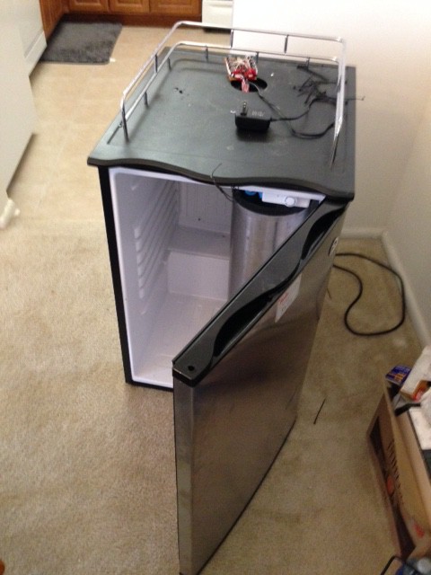
The following photos are a quick overview of our first design. Our initial concept was to retrofit a kegerator. The kegerator would serve as the storage place for all the connected ingredients. This is the kegerator with a small ball-lock type keg inside, popular with home-brewers:
![]() The first thing we designed was a 3D-printed spout that could lock into the hole already manufactured into the kegerator top. Here are some pictures of that:
The first thing we designed was a 3D-printed spout that could lock into the hole already manufactured into the kegerator top. Here are some pictures of that:![]()
![]()
![]()
This picture shows a close-up of the piece of the faucet which held the end of the hoses in place. They were simply pushed into the holes, which were slightly smaller in diameter. The piece itself fit into notches inside the end of the faucet.
![]()
The ESP8266 and TIP120s were wired up on a small proto-board that was mounted at the rear of the faucet:
![]()
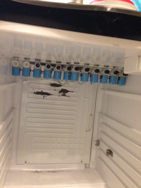
The valves were all mounted inside the kegerator on the ceiling for tube routing convenience:
![]()
As you can see here, the tubing was a tight fit to get through the hole with the wires:
![]()
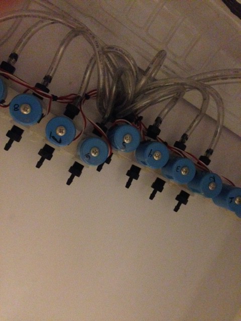
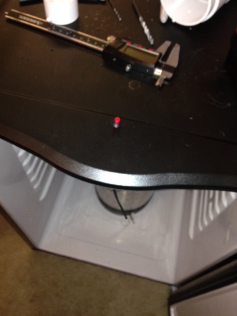
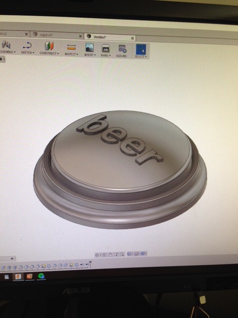
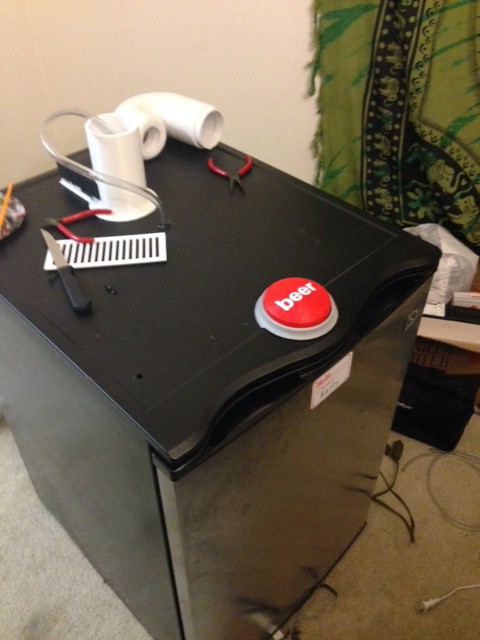
We chose to also have beer cooled in our kegerator. Since beer isn't mixed with anything we didn’t need to have beer dispensed automatically by the machine. For fun though, we made it dispense with the push of a button, where the button directly activated a valve for the keg. Here are some photos of the installation of the button. The 3D printed part was simply spot glued to the small red push-button I had lying around:
![]()
![]()
![]()
![]()
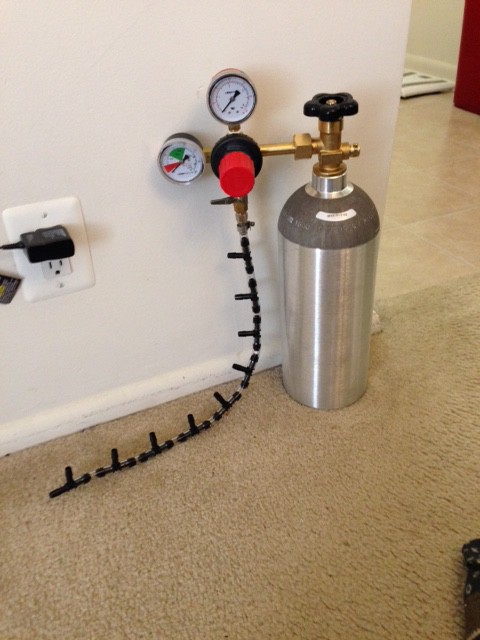
Here we have the CO2 tank and regulator. The pressure lines to the different ingredients were simply 'T' connections to the main output:
![]()
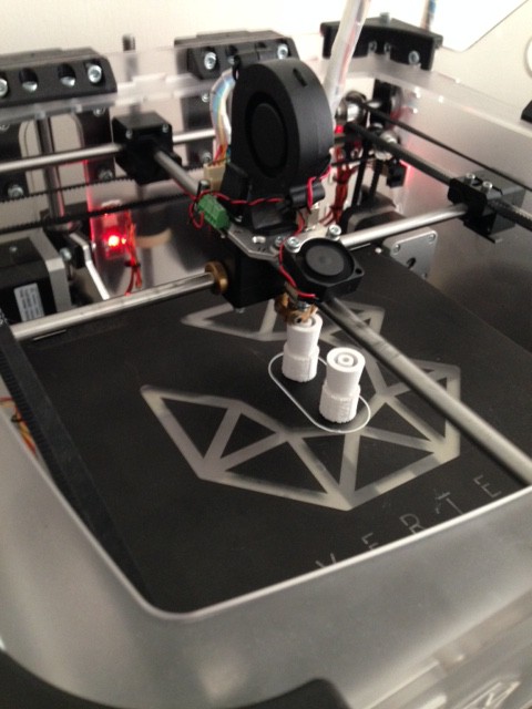
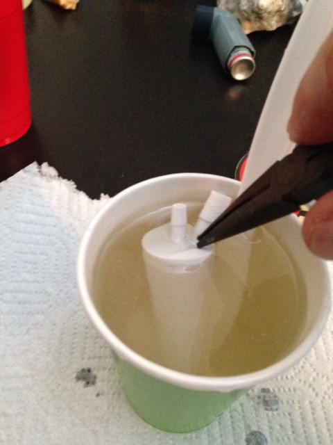
And then the main trouble we encountered, the bottle stoppers, are shown here. They were first 3D printed, then covered in a food-safe acrylic for strength and to make them air-tight. The outer surface had a molded covering of food-safe silicon to try and seal the 4PSI of pressure provided by the CO2 tank.
![]()
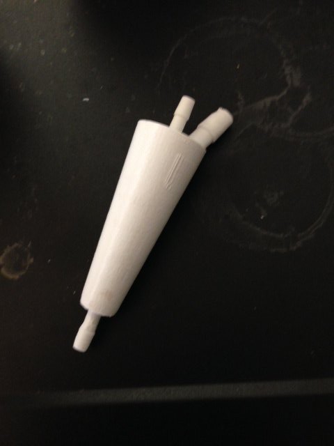
Here is the stopper before being coated in acrylic. The center, smaller barbed fittings are for the liquid and run through the piece as a solid pipe. A hose is attached to the bottom barb to extend to the bottom of the bottle. The pressurized gas line connects to the larger, angled fitting. The gas enters the bottle around the barbed fitting at the bottom of the stopper:
![]()
![]()
![]()
The approach worked, but there were several disadvantages and difficulties so we decided we needed to make some changes. We could only route hoses from 10 separate bottles in our setup, so this seriously reduced our system’s capability of making a large number of cocktails. The biggest problem, however, was coming up with a universal cap system that could be used on any bottle that was quick and easy to attach. Our attempt at a 3D printed stopper-like device with barbed ports for the hoses did not work. The problem was that we underestimated how easily the 4PSI used to pressurize the bottles could remove a cork.The silicon was too soft to provide a tight hold to keep the stopper from popping off the bottle. The CO2 was useful for keeping soft drinks carbonated, but a lot of CO2 would be wasted on ingredients that don't require carbonation, such as the liquors. This trouble, along with the aim to make the system as easy to make as possible for others, led us in a new direction.
The result was a complete redesign of the dispensing system and controller. The goals for the new design would be to use a vacuum system so that the bottles would not need to be pressurized and could be connected by just inserting one hose. The pressurized capability could still be used for special purposes such as 2-liter soda bottles, where a special cap could be used. Thus, carbonation would be preserved while providing a secure seal. Another aim was to minimize the requirement of any 3D-printed objects, since many people might not have access to such equipment. For revision 2, we wanted to use common DIY hardware and techniques as much as possible, while leaving room for creative implementation for those who would like to try their own implementation.
Part 2 will talk about the new Hardware Design.
-
A Collection of Web Pages
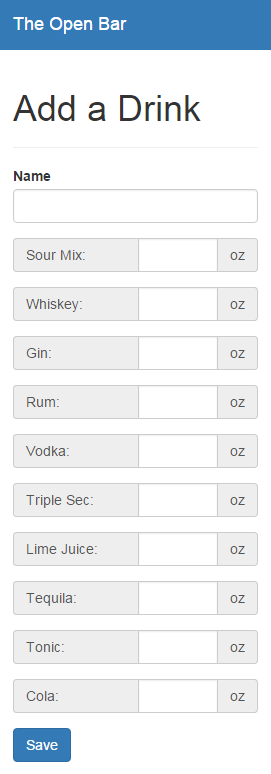
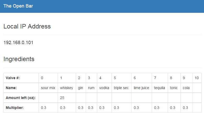
04/21/2016 at 20:41 • 0 commentsThis project has a collection of web pages where each handles a different part of the project. The main page links to the five pages that I have created. The “drinks” page simply calls the drinks API and lists all of the recipes that are stored in the MongoDB database. The “add-drink” page allows anyone to create a new drink to store to the database. When the station is known, the available ingredients are listed, so the user can just enter how many ounces of each they want in their drink and then save it. The “station” page lists some information about the station from its database entry. The station’s local IP address, all the valves and what they contain, along with the amount left in that container (to be implemented) and a multiplier (necessary for converting ounces in a recipe to time to pour that amount) are all listed.
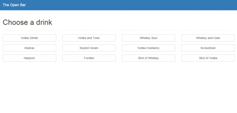
The “pour” page lists all available recipes. Clicking on one shows the required ingredients. The user can then pour that drink from this page. If any ingredients are unable to be added automatically by the machine, an info box will pop up asking the user to add the remaining ingredients.
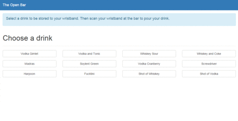
The “queuer” (a play on words for queueing a drink and using a QR code) page is the main interface option for patrons. They would scan the QR code on their wristband to open this page. The URL in the QR code will be appended with a unique ID that will behave as the user’s identification. If this is the first time the user has scanned their code, a helpful message will be displayed explaining how it works. Then the user can choose their drink, view the ingredients, and if they wish, store it to their QR code’s ID. The webpage will then update with the selected drink. The user will then go to the station and scan their QR code. The station will parse the ID from the QR code and query the database to find the selected drink. Then it will determine the recipe and pour the drink. The user could scan their QR code at the station again to pour the same drink, or scan it with a phone to choose their next drink.
-
Software Interface Decisions
04/21/2016 at 20:34 • 0 commentsEarly on, it was apparent that this project would require some sort of GUI so that the user can easily select a drink. We wanted something mobile-focused so that users can select their drinks from anywhere in the bar instead of waiting in line at some sort of kiosk. We decided to create a website instead of an app for a few reasons. Number 1, it’s a lot easier to get started using a website over an app. In our case, we have a QR code that, once scanned, loads the website directly, and uses a URL parameter to distinguish between users. We didn’t have any use cases that required the phone’s camera or bluetooth access, so we did not require the use of an app. This increases the user’s ability to get in quicker, because they do not need to get into their app store and download it first. Number 2, it’s a lot faster to implement changes and have all users up to date. This is really important in the early stages of development. And lastly, it will run on any device. Be it an android phone, iPhone, or tablet or any size.
I started on the software side of things at the beginning of 2016. I’ve had an interest in web development for a long time but have never created a large project on my own. I heard good things about the Angular framework, so I decided to use that. At the time, Angular 2.0 just started in beta so I thought it would be interesting to begin a new project with that. I followed the 5 min quickstart and tour of heroes tutorials and they were very helpful in getting started. I loved using TypeScript since it is a compiled language, which is very uncommon in web development. Atom is a great IDE with support for TypeScript. After completing the tutorials, I started on my own project. You can find that code on my personal Github. The branches on that repo are mostly the previously mentioned tutorials, but some of my new code is in there too. At the time, I was frustrated with the online support for Angular 2.0 and could not get very far with the project because I was so new to web development as a whole. I guess that is what happens when you decide to work with a project that is in beta. Due to my frustration, I made the switch to Angular 1. There are almost an endless amount of tutorials and help online for this framework, so I had no trouble progressing at a fast pace. I now feel comfortable enough with Angular that I think I could go back and work with Angular 2 on my next project, but I have no reason to change The Open Bar’s interface from Angular 1 to 2.
The source code for The Open Bar’s interface can be found on github. I started with the full MEAN stack because a coworker was using it for a project and he was very fond of it. Although I started by using Express for my page routing, I moved away from it and started using Angular’s built-in routing about halfway through the project. Right now it’s a Frankenstein of routing methods, but it would be too much work for hardly any benefit to move to exclusively using one. In the beginning when I was using express, I was also using Jade for my templating. I have a pretty extensive knowledge of HTML so learning a new language to do something that I already knew slowed me down. All of the recent view code is written in HTML and I have no reason to go back to Jade.
I also knew early on that I wanted to host using Heroku while the app was in development. I love that it uses a very similar command line interface as git, so I don’t need to learn something new to get working. I’ve also set my Heroku up so that it watches for changes in the master branch of the git directly and will automatically pull in changes as soon as they are available. This also enforces the use of branches in git for developing new code. I’m using a mLab MongoDB heroku add-on for my database storage. It allowed me to get started very quickly without any knowledge of databases. It’s a lot more powerful that I need for the simple databases that I have, but I appreciate how it’s linked to heroku.
Originally I was using Mongoose to query the database directly when I needed some information. It is incredibly powerful, and because of that, I had a hard time learning how to use it correctly. I only needed simple queries, so I moved to using monk and was impressed at how much easier it was to use for a database newbie. Eventually, I wrapped the monk database queries in an API. In a way, this slowed the application down because there was another layer of abstraction to the database queries, but I think it will allow more flexibility in the future (which I hear is bots in chat apps). I also wasted a lot of time changing my database’s JSON structures because I jumped into coding without really figuring out what I was doing first. For something as important as databases, I would suggest thinking through it a lot before getting started. Something that tripped me up for a while is the idea of accessing the database collections asynchronously. In my case, we have to access one collection using the user’s information, and then use some of the returned information to access another collection. I used Angular’s $q service for promises and deferred objects.
As I mentioned before, users have their own URL parameter that is stored in a QR code which acts as their access code to store their drinks. I spent a long time trying to keep the URL parameters in sync between pages until I found ngStorage, which I used to store the URL parameter locally, so it is persistent across pages. It was incredibly easy to use and very powerful and simplified my logic a lot.
As many other websites do these days, I used bootstrap to make my pages responsive. It’s super easy to use and just works. Unless you’re a designer, I don’t see why you would want to deal with all of the display logic on your own.
For a long time, I struggled with separating out the model, view, and controller. This is a very different point of view than I’m used to. After I wrapped my head around it, I loved the ability to create files that exclusively touched one part of the project and was able to link them together to create a pretty complicated puzzle. I could create a service that only deals with setting or getting the user, or only deals with the getting the drinks. The same thing goes for controllers that work to display only certain information. There’s a controller that displays the list of drinks which is used in two separate HTML pages by including that controller.
The Open Bar
A robot with a web GUI that can autonomously mix and pour cocktails
 To pour a drink, there are essentially 4 steps, using 3 different flows or "cycles". These cycles are identified in the diagram as the "Fill Cycle", "Drain Drink Cycle", and "Drain Rinse Cycle". The different cycles represent different states of the blue solenoid valves, creating different flows in the system. To elaborate, let me walk you through a complete drink pouring process.
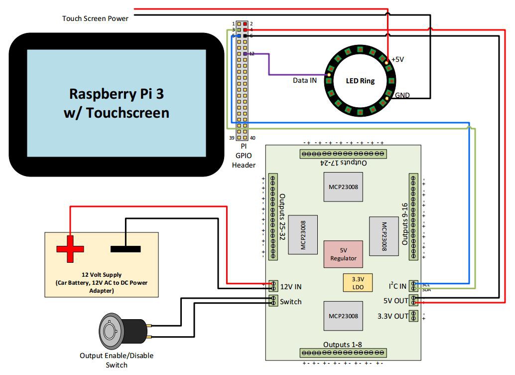


 The first thing we designed was a 3D-printed spout that could lock into the hole already manufactured into the kegerator top. Here are some pictures of that: