 MasterOfNull
Finished the remainder of the modeling work.
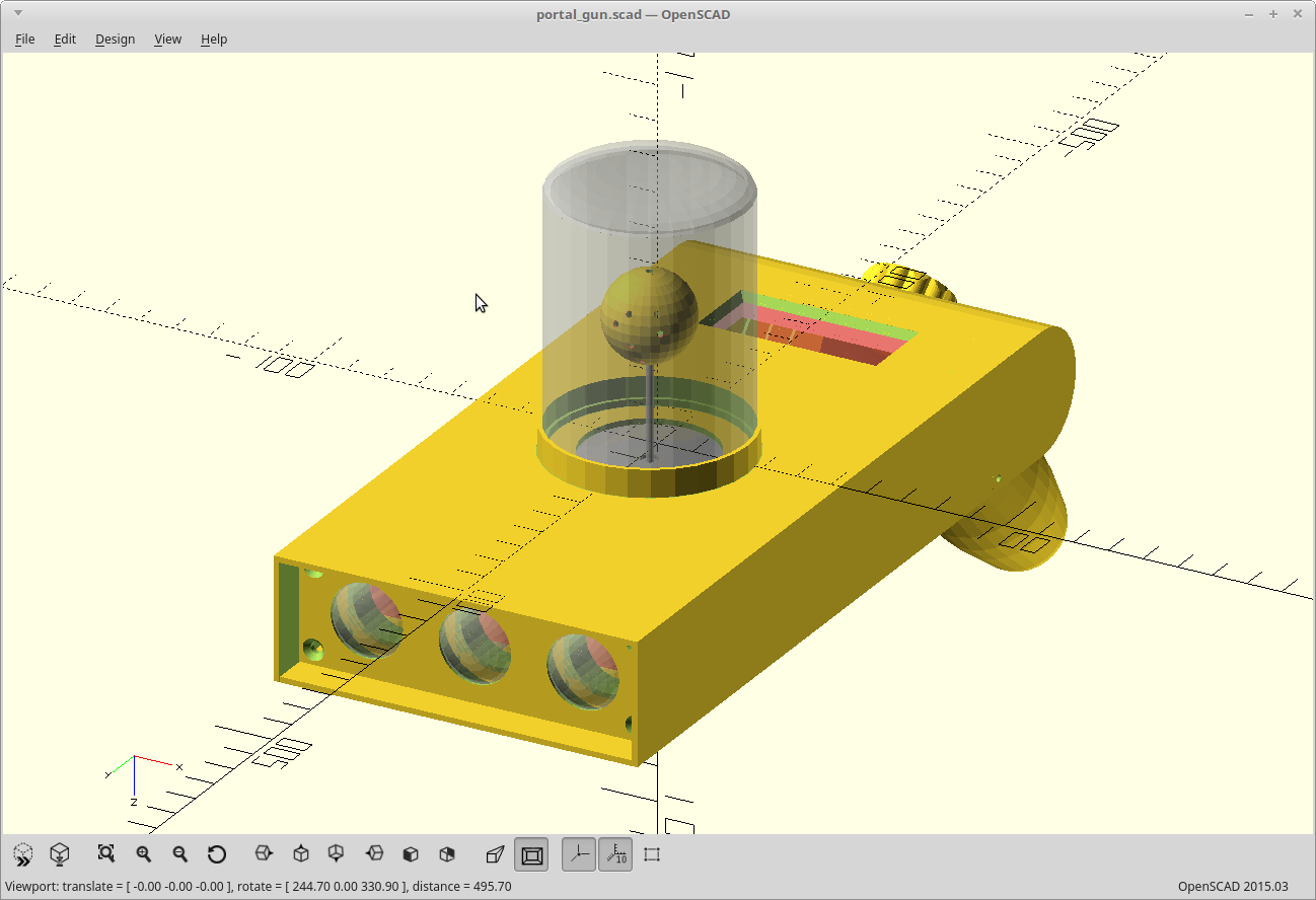
Battery mounts, encoder knob, encoder mount, fluid globe, display mount, and cover snaps done.
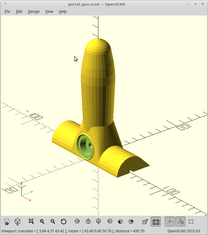
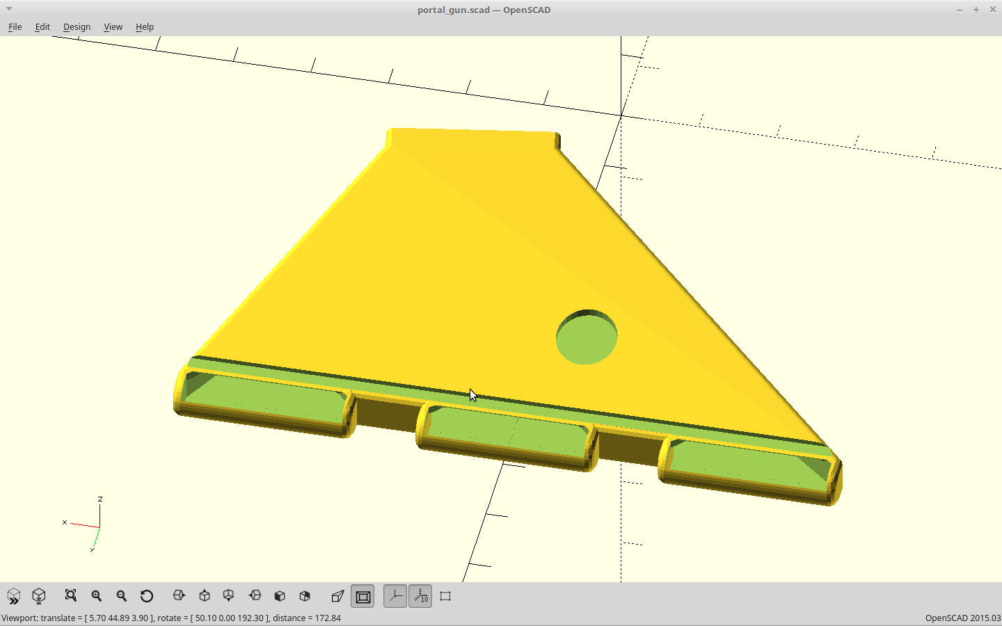
The handle got a recess so the encoder doesn't make the knob stick up.
The body had the battery mounts moved to the edges, and now I'm using 4 18650s.
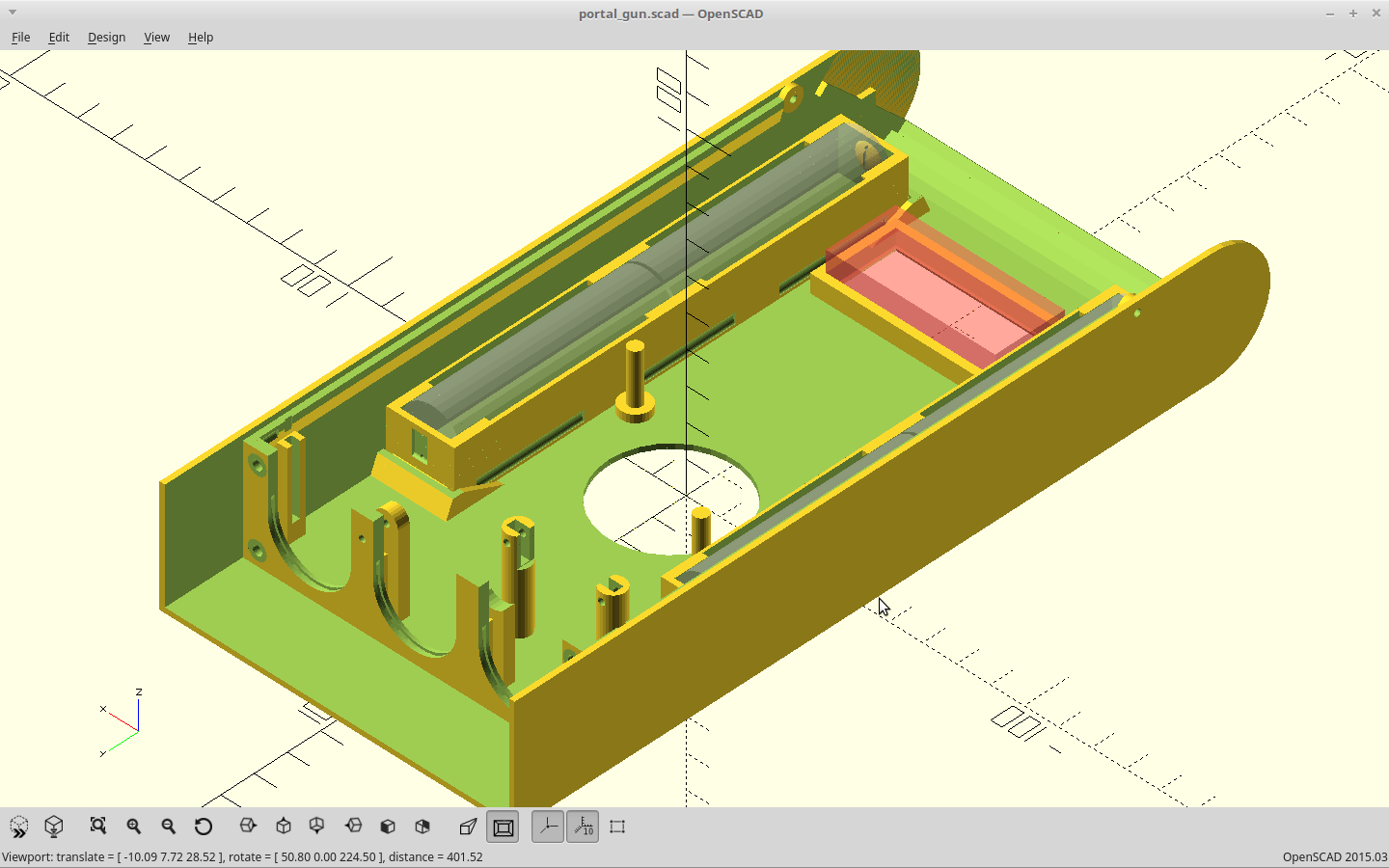
I sized the display cutout for a 4 digit .54 in LED display.
The top cover got it's snap closures and the speaker moved back a bit.
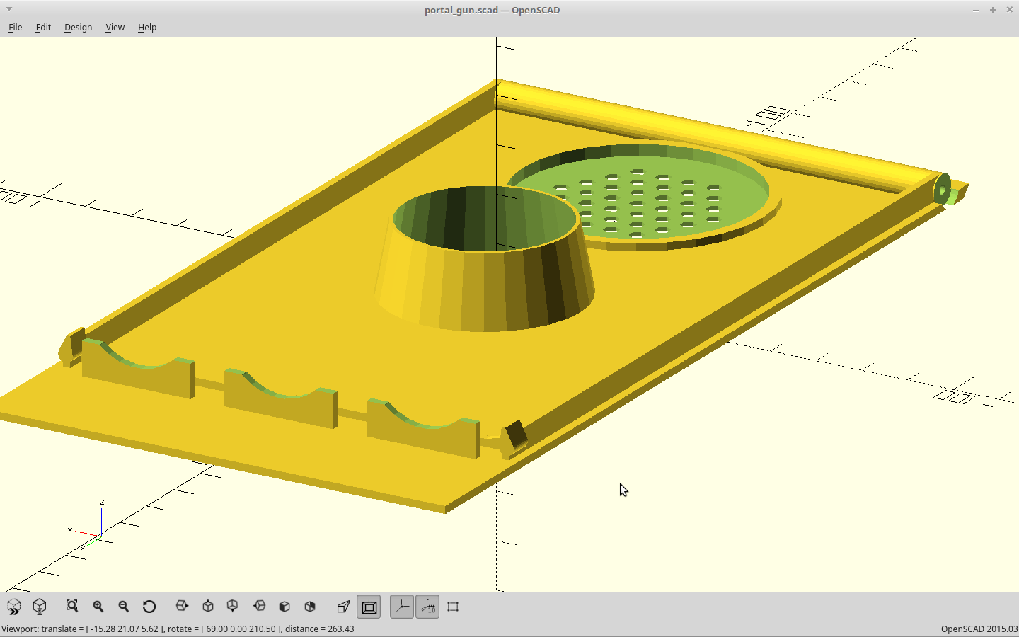
The fan duct got improved flow.
And.. the remainder of the parts with changes.
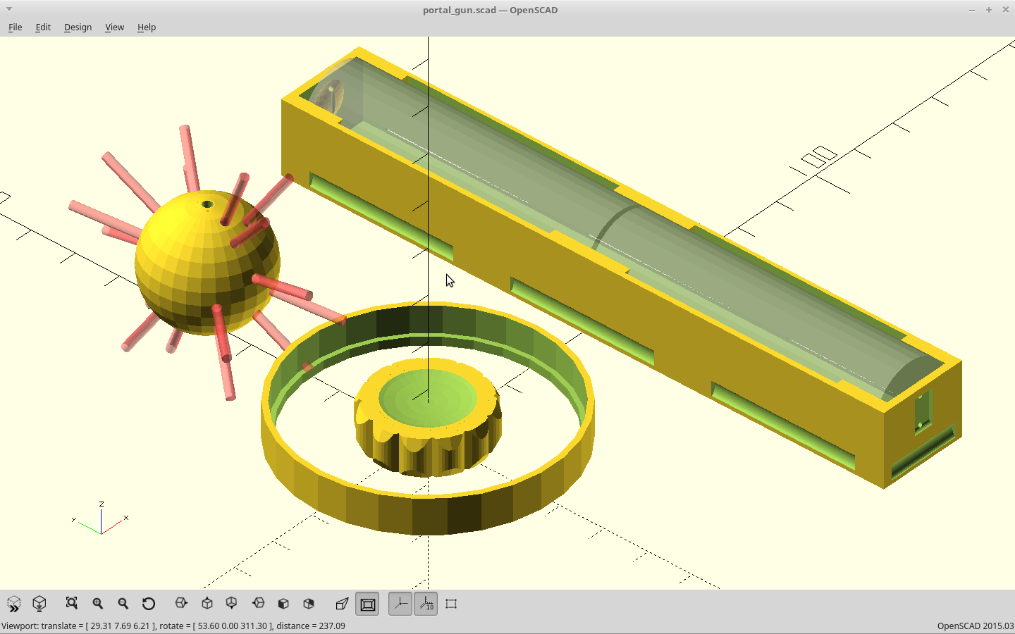
The spiky thing is the globe for the fluid simulation, the ring is the retainer for the fluid bottle, and the knob... well... is a knob now.
The battery carrier is now a 1x2 and I'll be using two of them, instead the old layout of a single 3x1 carrier. It fits better that way and leaves the middle largely open for the Arduino and mosfets.
Time to start printing, and on to the electronics.
Discussions
Become a Hackaday.io Member
Create an account to leave a comment. Already have an account? Log In.