Low Cost CO2 Laser Build
Goal: To assemble a working CO2 Laser from a minimum investment
using only tools one can find at your average home improvement store.
Goal: To assemble a working CO2 Laser from a minimum investment
using only tools one can find at your average home improvement store.
To make the experience fit your profile, pick a username and tell us what interests you.
We found and based on your interests.
Just thought I would post an update to this build as well as post some images of the plasma.
The first image is what happens when you have a leak, the tube glows a very bright purple and the plasma fills the chamber. This is a bad sign and meant that I had to check every seal to find the leaks in the system.
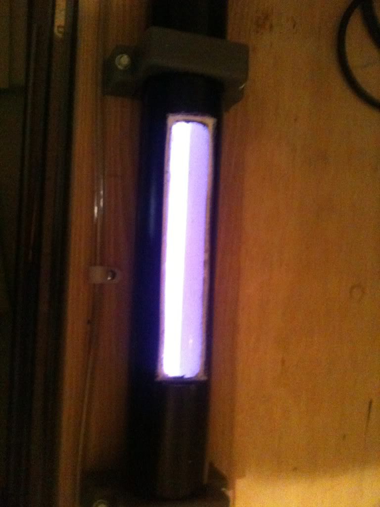
After some tinkering to check all the seals, this was the result and what I wanted to see ^^
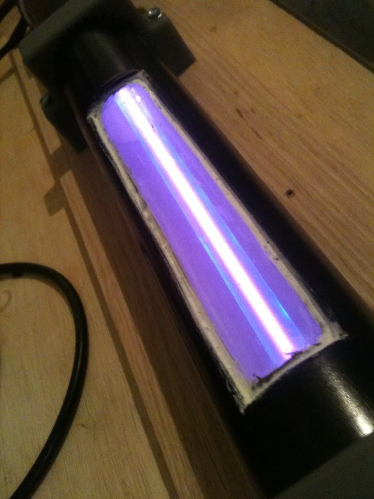
The plasma inside was a shade of pink, which was so bright I had issues taking an image to post here. My camera kept dimming itself to compensate.
Some of the issues I have found are the inner chamber cracking where the tube reaches the end of the water cooling jacket. This was solved by slowly powering up instead of a more "instant on". The bright flash of light and small explosion scared me the first time ^^;;
The laser itself does function and I wish to continue working on this project as I have time, as of this writing, the ternary computer project has most of my attention.
In other news, I have also received a number of different optics to experiment with at a future date as well as am considering building a much larger CO2 Laser.
Thank you everyone! :)
~ThunderSqueak
PVC Cooling Jacket for CO2 Laser
The adventure begins while I was walking around the local home depot looking at ideas on how to build the laser. I was sort of making it up as I went. Mapping things out in my mind. I wanted to keep the construction costs to a minimum and adapt things to work without having to order new or special components. Keeping in mind that simply buying a laser tube these days is actually pretty cheap (ebay as of the time of this writing has them for about 300 dollars).
The Purpose of doing it myself lets me tweak it, and to experement. It gives me the freedom that I cannot really get if I simply buy a sealed tube from ebay or another website.
For the Cooling jacket, I chose PCV. I did consider CPVC for its thermal characteristics but decided that a standard 2″ PVC would suffice. Thinking back, I could have easily gone with a smaller diamater but this way I can possibly keep it cooler or at least give me a small cushion of time if the pump were to quit working to turn it off before it overheats.
The Window I put in it used a tube from an old aquarium vacuum that I had recently replaced, it was a larger 2″ one that fit perfectly inside the PVC

The first step was to cut it to length, and then using my dremel I cut the window in the middle as shown in the photo. I then drilled two 1″ holes. One in the top, and one in the side. The reason for this is to allow the water to flow through the pipe, if they were both in the top water wouldnt flow at all, and if they were both in the side, there would be no place for the air bubble that would form to escape.
I had aquired the 12mm glass tubing from the neon guy in town. This turned out to be close to a half inch. With the drill, I made two holes in the endcaps of the pipe.
The final step was to use the PVC primer and glue. ONE NOTE, do this outside, the stuff stinks … and stains lenolium !!!! (Don’t ask me how I know this -.-;; )
Sorry I dont have construction photos for this part of the build. I didn’t think to take pictures of it as I went along until I was done assembling it.

I then coated all joints with JB weld. The glass tubing is in it and I tossed on two gromets, one on each end to keep it in place and safe from being broken while I constructed the rest of it. The grey clamps holding it are from the electrical department, for electrical conduit. The hose clamps around it were there to apply a little pressure to the clear tube inside it while the epoxy cured.
I then went over the whole thing with a black PVC paint to cover up any imperfections such as purple staining.
Be sure you use a plastic PVC safe paint.
5 coats later, with a light sanding between each coat. I simply suspended it while it dried overnight between coats. I would have left it outside but it started snowing.
This step is complete!
Mirror Mounts… where to begin, in many ways… these are the make or break it for this project. These have some very high tolerances and requirments. Especially considering I am doing this all by hand, after all, the goal of this project is to see if I can do this with as little as possible.
To start off… walking through the home improvement store I began looking at ways to create an electrode as well as alow gas to enter and exit the tube AND be able to adjust the mirrors in any direction or angle. Lots of ideas came to my mind, many of them were WAY to complex for this project. In the end, it hit me… I can simply pump the voltage through the mirror mount itself… and if I used a simple sharkbite T fitting I had a ready made way to pump gas in. For the mount itself, washers with some creative drilling and soldering was in order.
In the beginning, the main concern was a way to get the whole thing square and flush.
When I got home, I cut off the last barb on the sharkbite fitting, the washer I selected had a slightly to small center hole, so using a rat tail file I filed this out carefully to create a VERY snug fit… it was so snug a rubber mallet had to be used to get it into the fitting. The next step was filing down the end that would fit into the tube. For this I used a dremel, a fine file, and find sand paper. I test fit it as I went into the glass tubing, be sure you cut the end off the tube as they fire polish them and the diameter will be a lot smaller there. For a proper fit, you have to cut the ends


The next step was to drill holes for the mounts. Pick a drill bit that is slightly larger than the bolts you are going to use. You need them to be able to spin freely in the holes. The easiest way is to somehow stack all 4 larger washers, I simply used some zip ties. Put a mark along the edge of them so you can line them up again after… trust me on this. Then using a drill press if you have one… or being VERY careful if you dont, drill 3 holes through all 4 washers at the same time.


The next step was to solder some nuts over two of the washers over the holes you drilled. The easy way to do this is to simply thread the nut onto the bolt through the hole, this sort of autocenters it then also get a couple small bolts to solder face out. I didnt do this until the last step, in retrospect it would have been a lot easier to do it when I did this step. Best part of DIY stuff is making it up as you go :D
I also took the time to notch the washers that I put over the end of the T fittings. This was to make room for the bolts as you can see later. I sanded each surface to rough it up a bit, applied flux, then heated each with a toch and soldered. In the end, the result was as you see below.


After a while, and some major thinking… there was a problem… How to hold on the optics while the vacuum formed inside the tube. I needed a mirror mount.
This is where I had to solder on the small bolts as shown in the final product. then after, you make a loop of wire and using nuts simply tighten it down over the optics. If you are worried about slippage or damaging the optics, put some heat shrink onto the wire. I put a gromet into it to form the seal that will be needed later.

And there we have it, fully assembled mirror mounts ! :D
======
Nope… not quite, today while walking through the hardware store, I got a great idea upon seeing some pipe fittings and hose fittings! I picked up these, with the hopes to make my own lens focus for this unit. For the OC I plan on using a gold mirror with a hole drilled in it and a ZnSe window, just a flat plain old window. Why? Because they are cheap. Then I will use a convex ZnSe Lens that I have and make my own variable focus :D

The next step was soldering it to the adjustment, I removed the old screws that I had soldered onto the mirror mount. The next step was centering the hose fitting and soldering it on. The excess solder on that one side is from the old retention bolt, I didnt bother to remove it. I did verify that the joing was 100% sealed with the use of flux and then testing under water as before. So far so good.


After this, I remounted it to the laser and installed the gaskets for this system. after which I took the pictures of some possible configurations. :D Lots of possibilities with this system AND it should make a nice heatsink for the optics.
Total cost of this addition, 6 dollars per side. I do need to go pick up the parts for the other side now, and a standard solid “plug” to allow for better contact and heat disipation. Note: Do NOT over tighten! You will break the optics!


And now for the possible lens configuration.
Fist screw in the large one to retain the OC, then use the smaller one with a lens mounted in it. I can do a few possible configurations with this setup. Not sure if it will work or not, but that is the point of it. To experement and learn :D

on a side note, I need to adjust the screws to fix the alignment, it is crooked ;)
And NOW finished! … almost ;)
And now for assembling the laser tube itself. Things needed for this will be a bit of JB weld, a long thin dowl that fits inside your mirror mounts. This will help align them, much better than eyeing it. You will also need some 3/8th inch tubing and a few sharkbite fittings. Also, having a blow drier will help things out a LOT.
For the base of the laser I used oak. The reason for this is that it is already cured, very resistant to warping, and heavy, also it is a LOT stronger than MDF when you are screwing things to it. ALWAYS remember to predrill all holes.
Cut your glass tube to length, the easiest way to do this is score it using a file all the way around it. I simply went around it a few times until I could feel the score with my fingernail. After that, wet the score and with your thumbs positioned on the sides of your score, snap it like you were breaking a twig. Glass is actually pretty easy to work with as you can see. Just be careful to not burn yourself.

Make the glass a length so that when you put it inside the cooling jacket, about a quarter inch sticks out of each end. Mix up some JB weld and apply it to the smooth secion of your mirror mount, leave about a quarter inch on the end untouched by epoxy as this will also serve double duty as an electrode and we dont want epoxy insulating it. Put the dowl through the whole tube … all the way down the shaft. The reason for this os to hold the mounts ABSOLUTELY straight while the epoxy cures. Make sure you put enough in to form a good seal. Make sure the position of the gas input is in a position for easy access, I chose to place them straight up. Then epoxy around the glass and the end of the PVC cooling jacket to seal that. Leave this for about 24 hours to cure before going further.


The important thing is to make sure that you seal it. There can be NO air leaks, NO liquid leaks. To test this, after it is sealed, I filled up my bathtub, put a couple rubber stoppers in each end installed the tubes and litterally blew into it while it was submerged. I looked for air bubbles, I had none.. YAY! :D
To install the tubing, since it is a tight fit, warm up the tubing slightly with a hair drier. It will slip on easily and should shrink tight as it cools.
The next step was to run the lines and mount the tubing as well as install the connectors for attatching the vacuum pump and gas system. For the Electrical, I am going to simply use aligator clips (well insulated of course) and clamp onto the mirror mounts or the T fitting. I may come up with something else such as runing lines to terminals, but for now, I think simple is best.


This is how I am going to mount the Optics, I simply made a wire loop with some heat shrink, I am waiting on the optics to arrive as of this writing, so I put in a nylon washer that I had sitting on the bench to show how it holds. Seems to work really well :D K.I.S.S. Keep It Simple, Stupid! I am a firm believer in keeping it simple :D

Laser Tube is Complete!… sans optics
Create an account to leave a comment. Already have an account? Log In.
pls some one send me this project pictures. If you can see them
really amazing for CO2 laser (home edition)... but if you need not so powerful and massive device you can simply put a Endurance diode laser on any CNC router or 3D printer
Regarding mirrors, I've had GREAT success using a metric hole saw and used hard-drive platters to cut replacement mirrors for my 60W Epilog Helix. Been in operation for over a year with no measurable (with my laser "PowerWiz" tool) decrease in power.
I did this way back in 1980. Part of the book Laser experimenters guide did by a high school kid. I used a 1/2inch pipe flange, inserted a nipple, soldered, and machined flat. The nipple was an electrode. I still have the gold mirrors in fine shape. 12k 100 ma neon sign former, 20 amp variac, freezer compressor as vacuum pump, dry ice, TV stacked diodes for bridge ckt, high voltage wire, jbweld will outgas and give you problems. Sputtering will happen. I used a glass tube and a water jacket. 10 micron, fun stuff. I can build that $10 laser for $300. Who can resist.
Did you get this to work? Is there a YouTube video? What is the wavelength and power?
Great project and innovative thinking. Well done.
Become a member to follow this project and never miss any updates
 polyfractal
 David H Haffner Sr
 Jack Pearse
Hi,
I really like your project and build something similar myself right now.
Therefore, I have two questions where I really struggle.
1. The output coupler. You used 1. A mirror, 2. A flat znse window and 3. Another convex lense (probably independently of the tube, just to focus the beam to cut/engrave material), correct?
2. How did you align the mirrors towards each other? How can you set them perfectly parallel to each other?
Thanks a lot.