-
Display and Microcontroller
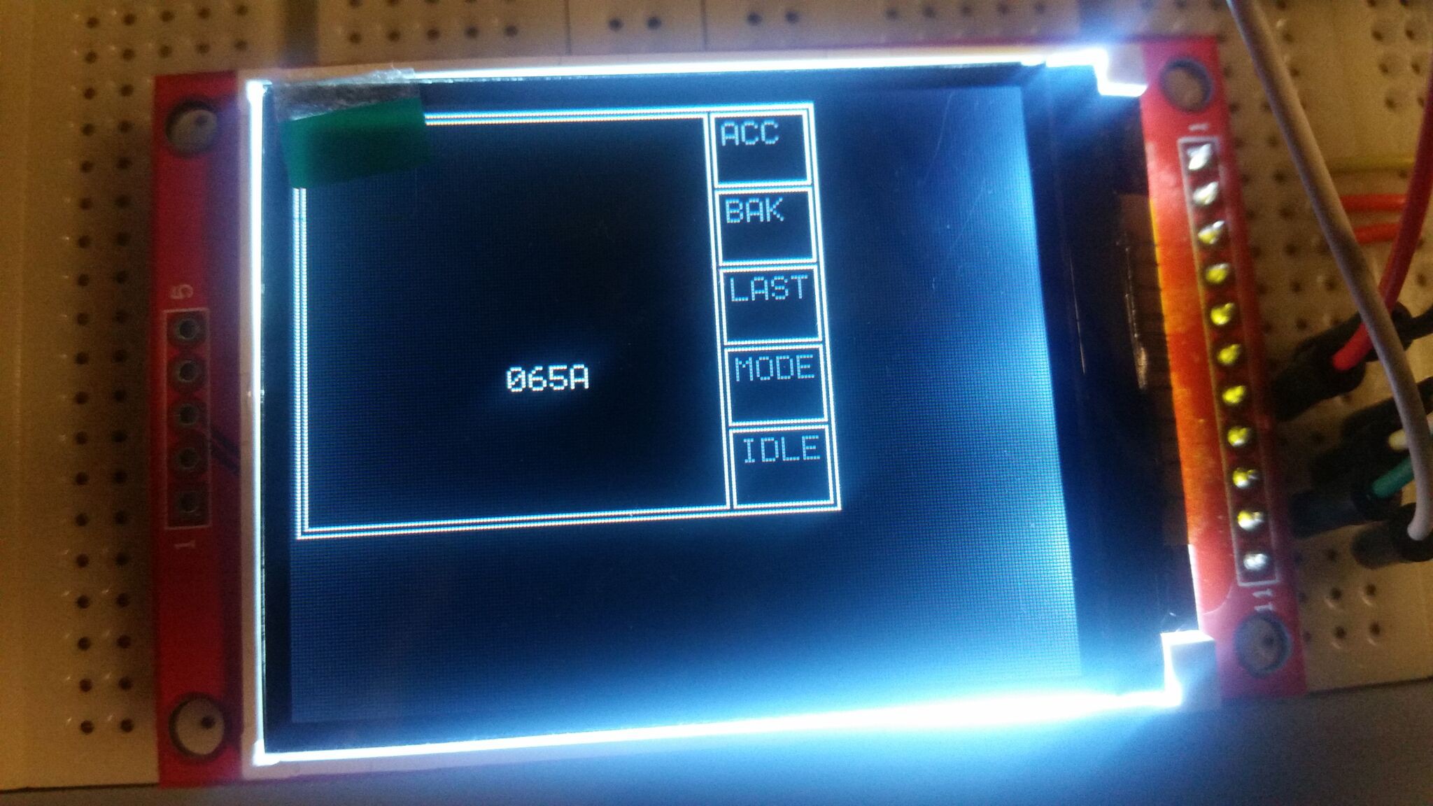
11/29/2016 at 19:17 • 0 commentsDuring the last months we have experimented with some hardware. We found a cheap 2.2 inch display on Ebay with a 176x220 pixel resolution called ILI9225. It was the cheapest display we could find (about $4) that had enough pixels to display the TIS-100 GUI.
We also bought some AVR ATMEGA328P-PU microcontrollers, the same one as the Arduino UNO R32 uses, but we ended up using an Arduino board for the tests so far.
The next step was to try out the display. We assumed that since the display seemed popular, there would be many graphics libraries that supported it. It turned out to not be widely supported. We found the u8glib library that had a nice API and supported many displays (but not ours). We tried to add a driver for our display to it and actually got it working. However, the limited clock speed of the AVR MCU combined with the design of the library made it very slow for us. The framerate was less than 1 Hz.
The u8glib library supports drawing many kinds of graphics (text, polygons, etc) using a limited amount of memory. It does so by running the graphics code multiple times. Each time it masks away everything except a few lines, an thus only needs to use memory for those lines. Our driver was also using an inefficient method to send pixel data, but we did not know that yet. For our uses it made the wrong trade-off between CPU and memory.
We then decided to write our own code for just what we needed: a matrix of characters, and a character to pixels mapping (that is, a font), dirty rectangle handling, and a way to turn rectangles of pixels into SPI commands. After some optimization of how we sent the pixel data and extensive debugging, it worked! We got an update rate of about 30 Hz.
![]()
-
Basic Communication Timing
03/16/2016 at 21:05 • 0 commentsWhen we were thinking about how the communication between the modules should work, we realized that we did not know how TIS-100 behaved in certain cases.
The first unknown was when reads and writes to neighboring nodes occur during a machine tick. For example, is it even possible for a node to read and write during a single tick? Consider the following program:
Node A              Node B

MOV 1, RIGHT      | MOV LEFT, LEFT
ADD RIGHT         |
Its behavior can be described like this. Each game tick can be divided into a read phase and a write phase. Each instruction first executes its read operation (if any). If no value could be read, the node stalls for the whole tick and tries again in the next read phase. Then the instruction executes its write operation (if any). This signals to a neighboring node that data is available to read. Since writes occur after reads, the writing operation can never complete during its first tick. This "wasted" tick is not counted as idle time by the game.
The behavior of the code above can therefore be described as follows:
Node A                         Node B

1R -                         | 1R No value to read
1W Signal value available    | 1W -

2R Transmit value            | 2R Receive value
2W -                         | 2W Signal value available

3R Receive value             | 3R Transmit value
3W -                         | 3W -
Since Node B has no value to read for the first tick, it is idle here. This means it has 33% idle time, which is consistent with the value shown in the game. Both programs turn out to take exactly three ticks per iteration.
This cleared up our intuition for a while. Then we thought about ANY... Stay tuned for the next post!
 Rasmus Svensson