-
Keep going...
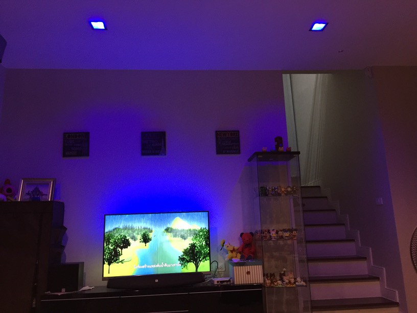
03/25/2016 at 18:02 • 0 commentsA few day ago, I tried some demo of the SkyLight. The result was vary POOR.
The Big problem was some glitter after SkyLight is enable. RF module used more time to send packet that make some serial packet from raspberry pi lost in the middle of Adalight packet train. There is a weak point of Adalight protocol that is not check a complete of the whole packets. Rx buffer was increased to make it better however arduino uno also reached their limit.
I've surveyed another solution founded this : Hyperion-Controlling multiple devices. That is a good idea to separate Ambient light and SkyLight controller.
- Conventional ambient light is controlled by raspberry pi directly.
- SkyLight is controlled via arduino uno exclusively.
The surveyed document which is in the link is very clearly, I, however, take a time to experiment.
----- MAY THE FORCE BE WITH ME -----
-
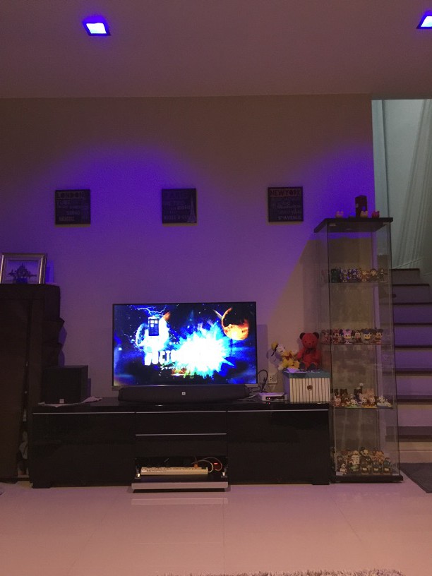
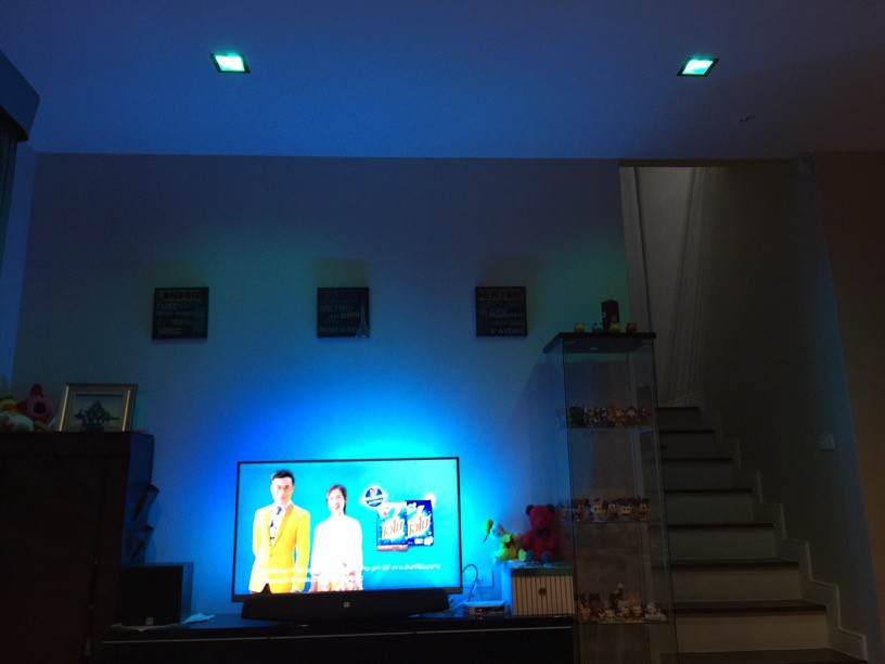
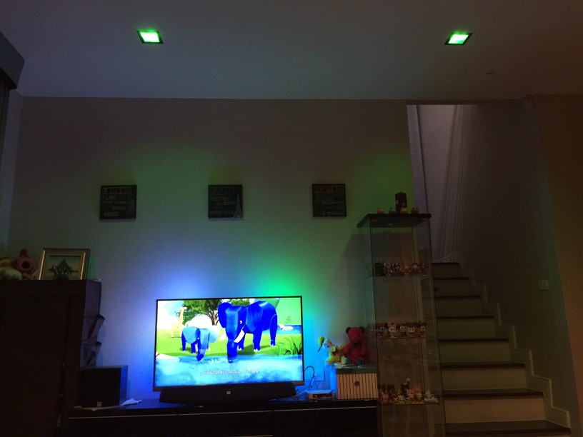
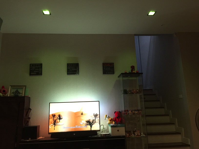
First Demo
03/23/2016 at 16:44 • 0 commentsDetail will come later :-)
It's look good.
I need more time to calibrate color mapping of bulb.
-
Rewrite code with FastLED + Gamma Correction
03/21/2016 at 18:59 • 0 commentsToday, i rewrite a code of ambient light of arduino module applied FastLED library carefully. Why? there are 3 important thing, 1) the legacy code of adalight is based on SPI that is used by a RF module too. I think move pin in code of adalight from HW to SW is not complicated. 2) FastLED library support many LED brand. Finally, Gamma Correction is applied.
/* This SkyLight Demo used Adalight(From octows2801 lib) + FastLED lib  */

#include "FastLED.h"

// How many leds in your strip?
#define NUM_LEDS 50

// For led chips like Neopixels, which have a data line, ground, and power, you just
// need to define DATA_PIN.  For led chipsets that are SPI based (four wires - data, clock,
// ground, and power), like the LPD8806 define both DATA_PIN and CLOCK_PIN

//--- SPI ---
//#define DATA_PIN 11
//#define CLOCK_PIN 13

//--- Software ---
#define DATA_PIN 2
#define CLOCK_PIN 4
#define GND_PIN 5

// Define the array of leds
CRGB leds[NUM_LEDS];

// Gramma Correction (Defalt Gamma = 2.8)
const uint8_t PROGMEM gammaR[] = {
    0,  0,  0,  0,  0,  0,  0,  0,  0,  0,  0,  0,  0,  0,  0,  0,
    0,  0,  0,  0,  0,  0,  0,  0,  0,  0,  0,  0,  0,  1,  1,  1,
    1,  1,  1,  1,  1,  1,  1,  1,  1,  1,  1,  2,  2,  2,  2,  2,
    2,  2,  2,  3,  3,  3,  3,  3,  3,  3,  4,  4,  4,  4,  4,  5,
    5,  5,  5,  5,  6,  6,  6,  6,  7,  7,  7,  7,  8,  8,  8,  9,
    9,  9, 10, 10, 10, 11, 11, 11, 12, 12, 12, 13, 13, 14, 14, 14,
   15, 15, 16, 16, 17, 17, 18, 18, 19, 19, 20, 20, 21, 21, 22, 22,
   23, 24, 24, 25, 25, 26, 27, 27, 28, 29, 29, 30, 31, 31, 32, 33,
   33, 34, 35, 36, 36, 37, 38, 39, 40, 40, 41, 42, 43, 44, 45, 46,
   46, 47, 48, 49, 50, 51, 52, 53, 54, 55, 56, 57, 58, 59, 60, 61,
   62, 63, 65, 66, 67, 68, 69, 70, 71, 73, 74, 75, 76, 78, 79, 80,
   81, 83, 84, 85, 87, 88, 89, 91, 92, 94, 95, 97, 98, 99,101,102,
  104,105,107,109,110,112,113,115,116,118,120,121,123,125,127,128,
  130,132,134,135,137,139,141,143,145,146,148,150,152,154,156,158,
  160,162,164,166,168,170,172,174,177,179,181,183,185,187,190,192,
  194,196,199,201,203,206,208,210,213,215,218,220,223,225,227,230 };

const uint8_t PROGMEM gammaG[] = {
    0,  0,  0,  0,  0,  0,  0,  0,  0,  0,  0,  0,  0,  0,  0,  0,
    0,  0,  0,  0,  0,  0,  0,  0,  0,  0,  0,  0,  1,  1,  1,  1,
    1,  1,  1,  1,  1,  1,  1,  1,  1,  2,  2,  2,  2,  2,  2,  2,
    2,  3,  3,  3,  3,  3,  3,  3,  4,  4,  4,  4,  4,  5,  5,  5,
    5,  6,  6,  6,  6,  7,  7,  7,  7,  8,  8,  8,  9,  9,  9, 10,
   10, 10, 11, 11, 11, 12, 12, 13, 13, 13, 14, 14, 15, 15, 16, 16,
   17, 17, 18, 18, 19, 19, 20, 20, 21, 21, 22, 22, 23, 24, 24, 25,
   25, 26, 27, 27, 28, 29, 29, 30, 31, 32, 32, 33, 34, 35, 35, 36,
   37, 38, 39, 39, 40, 41, 42, 43, 44, 45, 46, 47, 48, 49, 50, 50,
   51, 52, 54, 55, 56, 57, 58, 59, 60, 61, 62, 63, 64, 66, 67, 68,
   69, 70, 72, 73, 74, 75, 77, 78, 79, 81, 82, 83, 85, 86, 87, 89,
   90, 92, 93, 95, 96, 98, 99,101,102,104,105,107,109,110,112,114,
  115,117,119,120,122,124,126,127,129,131,133,135,137,138,140,142,
  144,146,148,150,152,154,156,158,160,162,164,167,169,171,173,175,
  177,180,182,184,186,189,191,193,196,198,200,203,205,208,210,213,
  215,218,220,223,225,228,231,233,236,239,241,244,247,249,252,255 };


const uint8_t PROGMEM gammaB[] = {
    0,  0,  0,  0,  0,  0,  0,  0,  0,  0,  0,  0,  0,  0,  0,  0,
    0,  0,  0,  0,  0,  0,  0,  0,  0,  0,  0,  0,  0,  0,  0,  1,
    1,  1,  1,  1,  1,  1,  1,  1,  1,  1,  1,  1,  1,  2,  2,  2,
    2,  2,  2,  2,  2,  2,  3,  3,  3,  3,  3,  3,  3,  4,  4,  4,
    4,  4,  5,  5,  5,  5,  5,  6,  6,  6,  6,  6,  7,  7,  7,  8,
    8,  8,  8,  9,  9,  9, 10, 10, 10, 10, 11, 11, 12, 12, 12, 13,
   13, 13, 14, 14, 15, 15, 15, 16, 16, 17, 17, 18, 18, 19, 19, 19,
   20, 20, 21, 22, 22, 23, 23, 24, 24, 25, 25, 26, 27, 27, 28, 28,
   29, 30, 30, 31, 32, 32, 33, 34, 34, 35, 36, 37, 37, 38, 39, 40,
   40, 41, 42, 43, 44, 44, 45, 46, 47, 48, 49, 50, 51, 51, 52, 53,
   54, 55, 56, 57, 58, 59, 60, 61, 62, 63, 64, 65, 66, 67, 69, 70,
   71, 72, 73, 74, 75, 77, 78, 79, 80, 81, 83, 84, 85, 86, 88, 89,
   90, 92, 93, 94, 96, 97, 98,100,101,103,104,106,107,109,110,112,
  113,115,116,118,119,121,122,124,126,127,129,131,132,134,136,137,
  139,141,143,144,146,148,150,152,153,155,157,159,161,163,165,167,
  169,171,173,175,177,179,181,183,185,187,189,191,193,196,198,200 };


void setup() {
  // sanity check delay - allows reprogramming if accidently blowing power w/leds
  delay(500);
  //FastLED.addLeds<WS2812,DATA_PIN,RGB>(leds,NUM_LEDS);
  //FastLED.addLeds<WS2801, RGB>(leds, NUM_LEDS); // --- SPI ---
  FastLED.addLeds<WS2801, DATA_PIN, CLOCK_PIN, RGB>(leds, NUM_LEDS); // --- Software ---

  Serial.begin(115200);
  Serial.setTimeout(500);

  // --- LED test ---
  pinMode(GND_PIN, OUTPUT);
  digitalWrite(GND_PIN, LOW);

  for (int i=0; i<NUM_LEDS; i++)
    //leds[i] = CRGB(128,128,128);//half White
    leds[i] = CRGB(128,128,128);//half White
  FastLED.show();
}


unsigned int state;
int32_t lastResponse;
int32_t now;

unsigned int count=0;
unsigned int total=0;


void loop() {
  unsigned char buf[3];
  if (!Serial) {
    while (!Serial) /* wait */ ;
    delay(20);
    Serial.print("Ada\n");
    lastResponse = millis();
    state = 0;
    count = 0;
  }

  now = millis();

  if (state == 0) {
    if (Serial.available() == 0) goto wait;
    state = (Serial.read() == 'A') ? 1 : 0;
    lastResponse = now;

  } else if (state == 1) {
    if (Serial.available() == 0) goto wait;
    state = (Serial.read() == 'd') ? 2 : 0;
    lastResponse = now;

  } else if (state == 2) {
    if (Serial.available() == 0) goto wait;
    state = (Serial.read() == 'a') ? 3 : 0;
    lastResponse = now;

  } else if (state == 3) {
    if (Serial.available() < 3) goto wait;
    Serial.readBytes((char *)buf, 3);
    if ((buf[0] ^ buf[1] ^ 0x55) == buf[2]) {
      count = 0;
      total = buf[0] * 256 + buf[1] + 1;
      state = 4;
    } else if (buf[0] == 'A' && buf[1] == 'd' && buf[2] == 'a') {
      state = 3;
    } else if (buf[1] == 'A' && buf[2] == 'd') {
      state = 2;
    } else if (buf[2] == 'A') {
      state = 1;
    } else {
      state = 0;
    }
    lastResponse = now;

  } else if (state == 4) {
    if (Serial.available() < 3) goto wait;
    Serial.readBytes((char *)buf, 3);
    if (count < NUM_LEDS) {
     //leds.setPixel(count, (buf[0] << 16) | (buf[1] << 8) | buf[2]);
     buf[0] = pgm_read_byte(&gammaR[buf[0]]);
     buf[1] = pgm_read_byte(&gammaR[buf[1]]);
     buf[2] = pgm_read_byte(&gammaR[buf[2]]);
     leds[count] = CRGB(buf[0], buf[1], buf[2]);
    }
    count++;
    if (count >= total) {
      //leds.show();
      FastLED.show();
      state = 0;
    }
    lastResponse = now;

  } else {
wait:

    if (now - lastResponse > 1000) {
      while (Serial.available()) Serial.read();
      Serial.print("Ada\n");
      state = 0;
      lastResponse = now;
    }
    if (now - lastResponse > 15000) {
      //allColor(0);
      for (int i=0; i<NUM_LEDS; i++)
        leds[i] = CRGB(1,1,1);//black + small light
      FastLED.show();
      lastResponse = now;
    }
    if (now < lastResponse) {now = lastResponse;}
    return;
  }

}
This code is not link any part of SkyLight yet, keep cool.
-
Test bulb functions
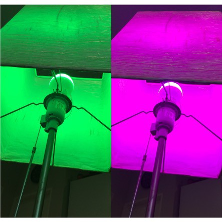
03/20/2016 at 18:28 • 0 commentsFirst, I install a bulb into floor lamp in a speed of light, at the same time pushing the buttons of remote insanely. OK. it work fine. I found it have 2 mode that is "RGB" and "warm white". they are independent. see this picture. Centre is a receiver circuit. Inner LEDs are RGB and the rim is warm white. they do not active at the same time. I think RGBW and RGBWW are identical inner RGB.
![]()
Second, Sniff RF signal from a IR remote using arduino and nRF24L01 breakout board. The method is on http://fablab.ruc.dk/controlling-the-mi-light-from-arduino/. They used Guino to interface an arduino with this sketch, However it worked on RF24 Library from "Reverse-Engineering the milight on-air protocol". Thank you.
Last, I observe for a while. found this:
- Control signal is 7 words = 3 ID, 1 Hue, 1 Brightness, 1 RemoteButton and 1 Incremental number. that is noted in above reference.
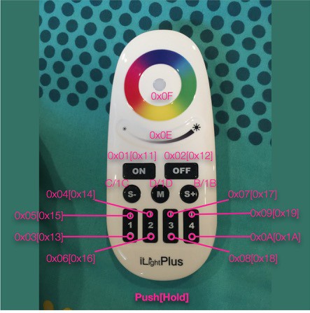
- Every button have own button key and hold button key for example press "ON" -> get 0x01, press "ON[hold]" -> get 0x10 (push key + 16 or +0x10). Remote key finally show:
![]()
- Hold "OFF" button is USELESS key, there is not functional. I plan to use this key to ENABLE and DISABLE the SkyLight.
- Colour wheel is base on HSL format. they only have 256 colour which is mixed of 2 major colour, R&G, G&B and R&B (No R&B&B simultaneous). The colour information is definitely lost then converted from RGB (24bits) to HSL(16bits, bulb protocol). Switching mode of RGB and WW is an alternative to avoid this effect if a transition is fast enough. I'll try.
- Control bulb from GUI, they work only parameter from matching RemoteButton. For that reason, control words is required 2 words, first is Hue, second is Brightness sequentially.
- Change mode, "M button", make a first ID value change. My remote that i have has ID which is [(176-184) 62 32]. The first ID can rotate 9 value = 9 mode.
Next, Control bulb from RGB signal via arduino.
 Songkord Thirachai