Quinn
Quinn-
THP Entry: System Design Document, Video and Requirements
08/21/2014 at 03:27 • 0 commentsThis log is intended to make clear all the entry requirement specifics in one place. Other log entries provide more details on the project and design.
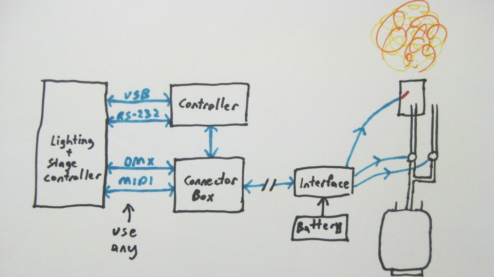
A block diagram of how it all connects is shown here: (System Design Document)
![]()
The controller schematic is shown in this project log.
The first prize video is also linked on the main page links, and here.
Some comments on the contest requirements:
This is hardware and software project where a completed functioning system will be built.
The system is connected in that is uses a variety of interfaces to connect to a stage and lighting control system. Interfaces supported are DMX, MIDI, RS-232 serial and USB. This allows a show operator to sequence the firing with other lighting and sound effects in a performance.
This project is being documented here, in build logs, parts lists and eventually build instructions. Schematics, software and images are provided here. Please see the extensive documentation provided in project logs.
This project is fully open hardware and open software, with everything needed to recreate it located here on hackaday.io
While the system as implemented here has safety concerns that make it an advanced project, several of the elements described are quite usable by many hackers, and can be used in a wide variety of other projects. Specifically, the sequencing controller, stage control system interfaces, prop construction and robust electrical control over long wires. Some examples of other projects could be a model rocket launch system, DIY dance lighting, and haunted house effects.
The dual stage propane poofer is an innovative technique which can produce more voluminous fireballs with a smaller outlet size than existing poofer designs. The smaller outlet allows more economical and easily available plumbing parts to be used. No prior instances of this technique could be found in the burgeoning fire art or theater pyrotechnic communities.
See the details section of this project above for an index to the topics covered in the many project logs. -
More details
06/13/2014 at 23:47 • 0 commentsThe ceremony control box:
![]()
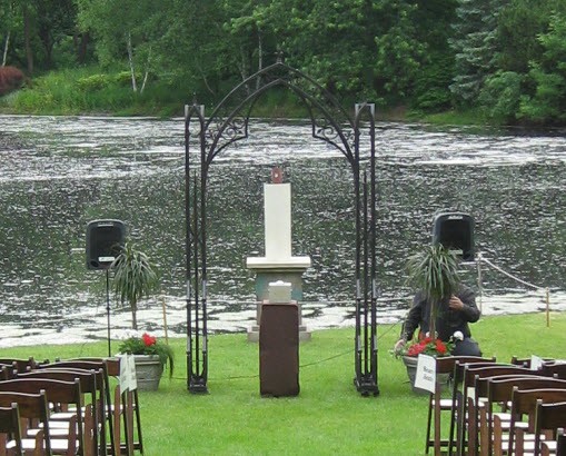
The candle in this case is 3 feet high and 12 inches wide on top of a 3 foot stone pedestal, located about 15 feet beyond the ceremony space. The pedestal is made of insulation foam, cut and screwed together, with decorative paint to make it look like stone. The backside is open to allow installation and access. The candle on top is made of a section of galvanized steel ducting with an opening in the back for installation and to allow air to flow up through the shield.
![]()
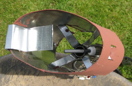
This is actually only a decorative shell to a two stage release propane poofer. A common propane poofer releases the contents of an accumulator tank past a flame to ignite it. To increase reliability, and prevent the visibility of the open flame pilot, Hot Surface Ignitors were used. These are off the shelf parts used in the electric ignition on many gas furnaces and water heaters. A pair was used for redundancy, though in testing, a single ignitor always worked. The ignitors were mounted in a wind shield at the top of the primary accumulator output pipe which served prevent the wind from cooling the ignitor, as well as to shield the ignitors from any propane coming out of the second accumulator output pipe. The most noteworthy difference of this from most poofers is the use of a second output path that is not ignited. This allows the release of propane into the air above the poofer prior to ignition to create more of a burning fireball effect than a jet.
![]()
The basics of a propane poofer involve a propane tank with regulator the passes "high" pressure gaseous propane and fills an accumulator tank. In this case, the accumulator is filled to 60psi.(a standard regulator for a propane grill is 0.5-1psi) The accumulator tank has a high flow path for the propane to release under the control of a solenoid valve and out the top to be ignited. A 3/4" pipe path is used here as it is the maximum output size of the easy to acquire accumulator tank, and can empty the entire tank in about 1.5-2 seconds. The poofer is fired by opening the solenoid valve which quickly releases the stored propane in the accumulator to create the fireball burst. This system of using an accumulator is required because a standard liquid propane tank has a limited rate of evaporating the liquid into gas to be released and burned. This allows high volume bursts to be released very quickly. Further discussion of the principals of a poofer is left to the reader to research elsewhere.
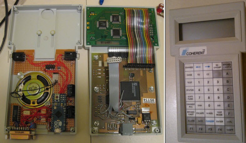
The remaining part of the system is a controller which implements safety features as well as runs programmed sequences to correctly time the two solenoid valves. This was built from a surplus hand controller, with an arduino micro, additional buttons, and IO drivers and protection built in. This was designed to be very tolerant of electrical noise, spikes and electrostatic discharage without damage or incorrect operation.![]()
During operation, there are several safety features. At the accumulator tank, there is a ball valve which can quickly close off the output as one emergency shutdown. At the controller, removing the cable functions as another emergency shutdown. The rest of the safety factors are for the flame effect operator and located at the controller. The primary is the positive manual enable. For the system to fire, an arming button must be held, which allows the operator to continually watch for site safety, and release if there are any issues. Releasing this button will prevent firing, as well as stop and shut down any sequence that is running. This arming button only makes the system active, as the keyswitches and main button for the couple actually fires the sequence. This allows the operator to be responsible for operation and safety of the system, while allowing the couple who are not responsible for the system to fire it. The controller also implements password protection, with it locked at powerup, as well as a single button to lock it.
-
Success!
06/13/2014 at 20:00 • 0 commentsThe wedding was this past weekend, and was a great success! I'll have a video, a summary and maybe some more pictures up soon, but wanted to get this out there.
I setup bright and early in the morning, getting everything installed and ready before returning later in the day better dressed. The minister gave a great lead up to the ceremony, explaining that this unity candle was a bit different, reflecting the background of the bride and groom. The guests were mostly unaware of what exactly the unity candle was. Actually, let me just quote D:
"To symbolize the joining of families and communities, we use the metaphor of a unity candle. Lit together, it joins two flames into one, representing lives and passions joined into one. Of course, given our bride, and our groom, our candle is a little more elaborate than some, and holds some special significance. It is represented by this box, which you probably can't see from where you are, but it has two key holes, one on each side. The key is somewhere in this room... no.(laughter) The keys represent the complex array of life experiences, of personality, of desires, and strengths, Maggie and Scott each of you bring to this relationship. Once the keys are in place, the bride and groom will, together, press the button at the center of the box, right on top. A symbol of their joint and unified purpose in their coming lives."
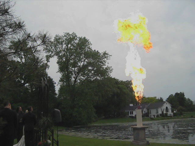
The bride worked at it, and eventually managed to find the key in her dress to much chuckle from the guests. The groom simply pulled the other out of his pocket, to even more laughs. Listening to the recording is great, because from the guests you could hear quite a few shocked reactions the moment it went off, followed by an energetic round of applause, while in the video you can see the couple grinning overjoyed, chuckling to themselves :)![]()
Sorry it isn't a great picture, it is a screen capture from a video which wasn't the best. I'm collecting another video or two, and will see what I can put up. The photographer knew all about this, so should have some good pictures as well. I'll share some of those as well if I'm able. Actually, funny thing about that. This was kept mostly a secret from the guests, though obviously I've been putting up logs here for some time under the assumption that no one was likely to come across this. Apparently when the couple had emailed the photographer that they were going to have a "unity fireball" along with a description, she was doing her own prep research and stumbled across this log. Sure enough, "unity candle fireball" in google points right here ;)
Overall, the bride and groom were overjoyed at how it all worked out, and the lasting memories they, as well as their family and friends will have.
Special thanks to M&S for asking me to do this for them, to A, K and J for helping create and decorate the decorative shell, to A for hand painting the box, A and J for code reviews, to D who helped bury wires, helped with multiple setups and tear downs, and was my safety backup in case of my illness, as well as to S who helped me take everything down after the ceremony.(formal wear is not so conducive to this sort of work)
To answer a question that was frequently asked, yes, the bride and groom did actually fire the candle flame. I stood in the wings with the controller to unlock and configure the system, as well as to hold down the positive manual enable button as long as the area was safe to launch, but the couple pressing the button actually did fire it. -
Putting it all together
06/11/2014 at 13:48 • 0 commentsAll the pieces were made with some flexibility in setup, as grass is never even, and at this site, there is a notable slope towards the pond. One of the primary techniques used was to drive stakes into the ground, then attach pieces to them at the right point to make things level.
The shell was installed first, by driving three stakes into the ground, and using some helpers to hold it level. Once it was determined in the correct spot, screws were driven through the stakes into the foam. The stakes are in the inside, so not seen. This robustly held the shell in place. A similar method was used for the tall table the button box was setup on.
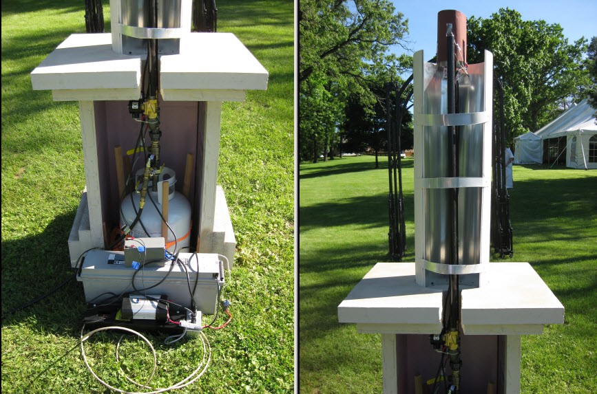
The accumulator tank obviously couldn't have screws attached, so instead, three stakes were driven into the ground around it, and a ratcheting tie down strap(in orange) was wrapped around and tightened. This allowed me to tip the tank to be vertical, despite the uneven ground. Once the strap was tightened, the tank was rock solid. Here is a picture of the backside of the setup from the rehearsal:![]() Behind the shell was a large industrial deep cycle battery(grey). This powered an AC inverter(black and grey, up front of the large battery) to power the hot surface igniters. I didn't measure the HSI's, and they didn't come with a datasheet, but both were powered fine with a 400w inverter without causing an overcurrent on it.
Behind the shell was a large industrial deep cycle battery(grey). This powered an AC inverter(black and grey, up front of the large battery) to power the hot surface igniters. I didn't measure the HSI's, and they didn't come with a datasheet, but both were powered fine with a 400w inverter without causing an overcurrent on it.
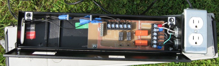
Also placed behind is the box with the relay card and switched AC outlets(at bottom, up front of the battery). There is a smaller 12V battery(grey, on top of larger battery) to drive the control system as I didn't want to tap into a battery capable of driving that much current for the long, smaller gauge wiring.
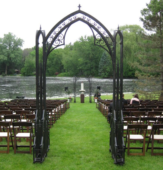
All of that is simply tucked behind the shell. The guests were all in one direction, so the workings were not visible to any of them when seated. I put up some stakes and a rope to keep anyone who arrive early away from the candle, and took it down prior to the ceremony. Here is how it looked from the front during the rehearsal:![]()
The propane line is shown in those pictures from the rehearsal, but for the actual ceremony, the accumulator tank was filled during setup, and this line as well as the LP tank were removed so they wouldn't be in pictures. This meant only one blast could be fired, which is all that was needed.
I only got one picture from the setup prior to the ceremony, though this does show where it was all located in relation to the guests.![]()
![]()
-
Installation wiring and connectedness
06/10/2014 at 16:09 • 0 commentsTo keep unsightly wires out of pictures, the wires between the button, controller and candle were surface buried. This was done by sinking a spade about 4" into the ground, prying at an angle, pushing the wire into the slot, then pulling the shovel out. Takes a bit of time, but with two people worked fine and made for a much nicer look. The wire was scrap, a 6 pair 22 gauge solid shielded outdoor rated cable. Not technically rated for direct burial, but plenty fine for several days.
Because of this, wires were run, cut to length and wired in place. To make this easier, all three points had screw terminals, so the ends of the cable were just stripped and wired in, without needing to worry about connectors.Inside the button box:
![]()
The button box has just the top lighted button, and two key switches on the side, with a simple terminal strip glued to the bottom.
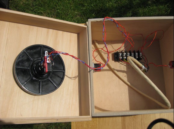
Candle relay box:![]()
This has the previously described relay board for controlling the solenoids and HSIs. When that board was designed, I simply used screw terminals for the inputs. This picture shown prior to connecting the inputs on the left of the circuit board.
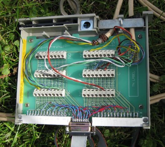
Controller breakout:![]()
I used a scavenged terminal module for this. The terminal board was originally a module to plug into some old test equipment, and was simply a set of screw terminals wired to a card edge connector. It was a great base because already had the terminals, had a screw clamp for securing the wires coming in, and a plastic case with a quick release cover screw.(cover not shown) To make it work for this application, I simply cut a channel into the [no longer used] card edge connector to mount a DB15, which I wired into the board. A simple ribbon cable connected between this and the controller.
As can be seen in the pictures, I doubled up the wires, stripping and twisting together both wires of a pair to act as one. This was not required, but I had the extra wires, and it reduced the resistance in the long wires. Approximately 200ft of wire was used.
I also wanted to take a moment to talk about connectedness. Being made up of multiple independent units, this project is inherently a connected device, passing communications between these blocks. Further, though not shown here, the controller supports serial communication both through USB as well as through an RS232 level UART.The USB serial connection is intended to load and save sequences. This allows a more convenient method for visualizing and programming sequences as well as performing backups.
The RS232 level UART is intended to communicate with other smart blocks in the system. For instance, this allows the project to be connected to a stage and lighting controller for firing in sequence with other effects.
-
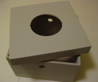
Ceremony Button
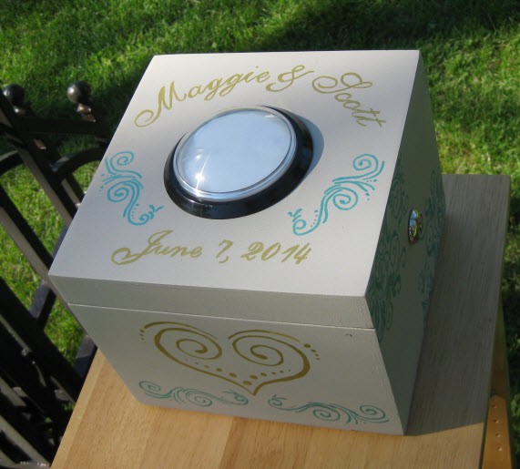
06/10/2014 at 02:37 • 0 commentsThe control for the couple was made out of a simple wooden box, like the sort found at craft stores. It was painted flat beige, and A. drew on a lovely design in the style of wedding and invitations. The box will serve as a memento for the couple afterwards, and I'm sure they'll wire it up to activate something in the future.
![]()
The key switches were mounted with simple holes in the side. I originally got the small key switches sold at Sparkfun, but found that they were just too cheap. I knew they were not real tumbler key switches, but was ok with that given these are more symbolic than for security. However, the physical feel and size of them just felt too much like a toy. I ended up ordering a set of real key switches from C&K.
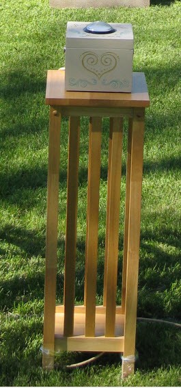
The firing button on the top is one of the "massive arcade buttons" from Adafruit, though Sparkfun also sells them. I wanted to reduce the black rim around it, so instead of just drilling the smaller 1" hole for mounting, I used an adjustable hole cutter, and mounted it flush. I simply used a file to create the two notches which prevent the button from spinning.![]() The box was placed on top of a tall table(a plant stand I believe) in the ceremony space. This picture was from the rehearsal. For the actual ceremony, the table was covered in a table cloth matching the wedding colors, and the wire was buried. The table was also attached to a pair of stakes to make it level.
The box was placed on top of a tall table(a plant stand I believe) in the ceremony space. This picture was from the rehearsal. For the actual ceremony, the table was covered in a table cloth matching the wedding colors, and the wire was buried. The table was also attached to a pair of stakes to make it level.![]()
-
Robust Electrical Control
06/09/2014 at 21:57 • 0 commentsThis project includes electronic control of things which are inherently dangerous. While there are a number of physical elements which improve safety, it is still controlling a large open flame. Because of this, there is little to no room for electrical issues causing accidents, and elements were incorporated to support this. Further, the use of long cabling introduces potential issues due to EMI. Plus ESD damage to chips really puts a damper on a project. This whole topic is commonly ignored in electrical projects because it doesn't always seem necessary. When it works, you'll not even notice it, when you don't include it, you'll likely notice the failures when you least want them.
Electro-Magnetic Interference can affect any electrical circuit, but longer wiring can work as an antenna which exacerbates potential issues. These lines can have spikes of voltage that seem to appear out of nowhere which can falsely trigger things. I incorporated a number of elements to combat potential issues.Surge protection and isolation in the controller. As discussed in the sections about the controller, Transient Voltage Surpressors were used on almost all lines going out of the controller. These, along with series resistance will block most of these spikes from entering the digital ICs, preventing their damage from EMI spikes, or ESD. These cannot handle the largest spikes as might occur from a nearby lightening strike, but will be able to handle most other situations. The digital input signals did not go to TVS's, but instead drove the emitter side of Opto Isolators. The Opto's prevent any surge spikes from getting past and into the ICs. The power line into the controller was fed through a diode to prevent reverse polarity, and into sizable capacitors to take most spikes. Past the capacitors were linear regulators, so most deviations will not pass through.
The surge protection and isolation prevent damage, but don't prevent errant signals. For instance, if there is a high input, a spike could be read as an brief low input, which may cause accidental triggers. One way to help mitigate is to require the signals to have a higher current drive. A normal digital input frequently requires less than 1mA of current to change the state, which EMI spikes can easily cause. To mitigate, higher current was required. Going into the Opto's, a 15mA minimum current was required to flow in order to pass the signal, which will block a larger number of the spikes. Software debouncing was also used as a second stage. On the outputs, the controller used a darlington array to drive open drain signals. This had sufficient drive to directly drive the relays at the candle. These relays required 60 and 100mA to toggle, which EMI is almost never going to be able to cause. Further, due to the slower switching time of relays(about 4ms in this case), there is sort of a basic "debouncing" in play, or looked at another way, a low pass filter. The relays also require sustained current to maintain operation, so even if a spike was able to activate them, they would just as quickly turn off.
It has been asked why I didn't use wireless instead of going to the effort of burying the wires. The simple reason is reliability. The hard wiring is going to work 100% of the time, while wireless is less reliable. Certainly wireless can be made more reliable, and robust communication protocol used to prevent accidental triggering, but it takes a lot more work, cost, and brings with it other issues of possible missed messages, and interference.
Though long wires were used(in this situation, about 200ft was used) and can really amplify the EMI levels received, the wiring I used was shielded and grounded at one end(candle only). The wiring was further buried for most of the length, which also helps.(well, except for a lightening strike traveling through the ground)The other key thing on robustness was in code review. I had two professional programmers review the code for safety issues, or possible failure states, and any concerns were addressed prior to use. Thanks to A and J for their help!
No ESD damage, or errant behavior was ever observed with the system. -
Rain Shield
06/09/2014 at 15:37 • 0 commentsGiven the nature of needing this to work, and the fact that it is constructed for an outdoor wedding, I needed to prepare for possible rain. The electronics could all be wrapped up in plastic, but I was concerned that rain falling on the hot surface ignitor could cool it, and prevent it from getting hot enough to ignite the propane. Or possibly worse, and crack it due to rapid change in temp. I cut a simple rain shield of of scrap sheet metal which just clips over the top to cover one of the HSIs. I ran this through testing, and though it does deflect the flame a little at an angle, it ignited fine.
![]()
-
Heat and cost estimates
06/05/2014 at 16:36 • 0 commentsI ran some estimates in a prior log about the heat output from this. The accuracy of this was restricted by some assumptions, namely that the pressure in the accumulator remains constant, and it assumed that only 1 valve was open. I had calculated this by using the flow rate of the valve from a datasheet. Instead, with some test data, we can recalculate based on the before and after pressure of the accumulator tank to determine the propane actually released.
The accumulator tank has a water capacity of 47lbs, which converts to 5.7Gal, and then to 0.76ft^3, I'll ignore the volume of gas held in the plumbing.
The average energy density of propane at room temp, atmospheric pressure is about 2450 BTU/ft^3.
Starting accumulator tank pressure is 60psi
Ending tank pressure estimated at 10psi
To calculate, we are going to figure out what volume the pressurized tank would need to be expanded to in order to get to atmospheric pressure. Rearranging Boyle's law, new volume = old pressure * old volume / new pressure = (60+14.7)*0.76 / 14.7 = 3.86ft^3
This is the atmospheric pressure volume of the entire accumulator worth at 60psi. Calculating again for the remaining gas after launching = (10+14.7)*0.76 / 14.7 = 1.28ft^3. This means that we released 3.86 - 1.28 = 2.58ft^3 at atmospheric pressure. With 2450 energy density, this means the output is 2450*2.58 = 6321BTU. This is actually remarkably similar to the original estimates. With 6321BTU of propane released in 1.5seconds, it could be compared to 15,000,000BTU/hr. If we take the burn time, (estimating 0.75sec burn time, it's probably a bit less), it would be 30,000,000BTU/hr when comparing to a furnace, so 300 times an average furnace in a 2500ft^3 home in the northern US. That is of course only sustained for that 0.75sec, as this system cannot maintain that rate due to evaporation rates of a 20lb tank, and the tank freezing.
For those curious, running the numbers suggests that a full 20lb tank of LP will last for about 55 of these blasts. Looked at another way, it is about US$0.50 in propane per blast. -
Parameter adjustments
06/04/2014 at 18:52 • 0 commentsWith the electronics done, they needed to be tested with the system, and I was now able to see timing affects of various delays, and tank pressure.
To simplify this description, we need to remember that there are two outputs of the tank. One vents straight up with nothing in the way, and no ignitor. This will vent the propane, and not ignite it. I will refer to this as vent. The second output has hot surface ignitor's at the opening which will ignite the propane that leaves. I will refer to this as ignited.
The sequence I started with, opens the vent, then after a 750ms delay, opens the ignited. Both are left open for another 750ms, then both shut off. The purpose of this was to get a volume of propane in the air above the candle before igniting. Being able to do this was a design feature from the beginning, which I came up with from researching. All of the examples I found on the web produced higher velocity flames, some even approaching "flame thrower" type looks. I've never found any examples of this pre-ignition venting technique, so as far as I know I came up with it just from thinking of various techniques for achieving the appearance I was after. This is part of the reason I wanted to log this project, to share the idea to others.
This 750-750 sequence worked well right off the bat. The accumulator tank pressure after running was <10psi(gauge is not very detailed below that), meaning nearly the entire volume was released, a positive sign. I went through a bunch of pressures, and when it came down to it, higher pressure was better for flame height and size as expected. I had a concern that high pressures would lead more readily to the flame thrower effect, as well as make the result quite loud. Given the pre-ignition vent, this wasn't a problem. In the end, I decided on running at 60psi.
Shortening the vent time reduced the flame size and height, and trended towards more of the flame thrower effect. Lengthening it didn't seem to help as I could tell that it ended up reducing the accumulator tank pressure a lot prior to the ignition release. I suspect this also would be impacted by too much of the vent propane drifting away and not being used.
The ignition time at 750 also seemed pretty good. Going up to 1250ms made for an obvious flame thrower effect at the end, which was undesirable in this situation. Shortening made for smaller flames. In the end, I ended up at 850ms as maximized without getting the flame thrower effect. That also points to the actual time that there is flame in the air.
The resulting effect is quite impressive. The flames reach more than 30ft in the air, and do look like the desired fireball. At about 30ft away, you easily feel the heat. The couple were present for some of this testing, and squeed with joy when they first saw it. I'll try to get a video up soon.
It is also noted that the dual stage release means that the accumulator tank is at a lower pressure before ignited release. This probably also has a large help avoiding the flame thrower effect.
At the higher pressures, it is noted that there is an extra delay prior to ignition, perhaps in the order of 250ms. That is, the ignition propane is released, and 250ms later, it is actually ignited. I believe this is due to needing to end up with the correct propane-oxygen mixture at the HSI. Possibly due to some of the high velocity propane falling back down or swirling down towards it. I think it may be a good idea to mount the HSI higher up than I did. I will look at modifying the mounting of the second HSI to be higher.
Though not yet tested in stronger breezes, I think it is best to substantially reduce the vent time as most of that propane will just be blown out of the area before ignition, and not serve any purpose.
The no wind/slight breeze sequence I intend to go with is: open vent, 750ms delay, open ignited, 850ms delay, close both.
The stronger breeze or more sequence I intend to go with is: open vent, 100ms delay, open ignited, 850ms delay, close both.
In testing, probably 20 nearly full accumulator tank releases over about 20 minutes, and the source LP tank was starting to slush up and the evaporation rate observed to be reduced. (The tank was about half full during this testing)


 Behind the shell was a large industrial deep cycle battery(grey). This powered an AC inverter(black and grey, up front of the large battery) to power the hot surface igniters. I didn't measure the HSI's, and they didn't come with a datasheet, but both were powered fine with a 400w inverter without causing an overcurrent on it.

 The box was placed on top of a tall table(a plant stand I believe) in the ceremony space. This picture was from the rehearsal. For the actual ceremony, the table was covered in a table cloth matching the wedding colors, and the wire was buried. The table was also attached to a pair of stakes to make it level.