Quinn
Quinn-
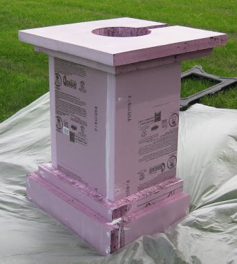
Candle shell
06/03/2014 at 14:25 • 0 commentsThis project is not only going to be up front of the couple, and the attendees, it is likely going to be in the background of many wedding pictures. Because of this, it cannot look like a propane tank with plumbing on it.
With some help, I created a decorative shell to look like a stone pedestal, with a large candle on it. The proportions were so that it would appear like a scaled up standard unity candle.
The shell is made from 2" thick insulation foam. This is a great, quick material to work with for decorative projects where you want bulk. This was done with a single 4x8' sheet, with cuts made with a hot knife foam cutter. Pieces were then screwed together with 4" long drywall screws. Given the nature of the foam, it is not super strong, but ends up more so than you'd expect. Care must be taken when screwing into foam as you cannot put much pressure on the screw going in, just letting the drill do the work. Screw heads, and gaps were filled with caulk. The design is simple, and is mostly just stacked pieces to look like a traditional stone pedestal. The top layer has a large hole to hold the candle piece which rests on the next layer down. It stands 3' tall, and is 28" wide/deep. Many thanks to K. and A. who helped me cut out and screw the pieces together.![]()
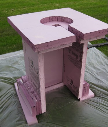
The pedestal is open on the back, with a slot in the top to allow it to be placed around the tank and plumbing. This also allows easy access to the valves. In our case, it will be placed next to a lake, so no one will be viewing it from the back.
Back side:![]()
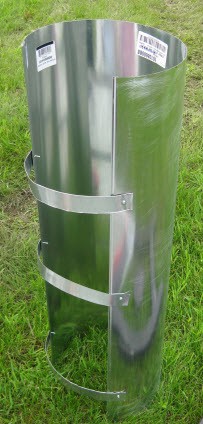
The candle is made from a 3' segment of 8" ducting, with some steel strips to hold a spacing to make it approximately 12" in diameter. This was done instead of purchasing 12" ducting because I wanted the large open strip in back to allow air to flow up past the nozzle and HSI when activated.![]()
The base was painted with a cream color base paint and speckle spray paint on top to make it look like stone. Note that you can only use some kinds of paint on this type of foam. Brushed on standard house latex paint works fine. You cannot use any spray paints, as it will dissolve the foam. With the base layer down, using the spray speckle on top was fine. Many thanks to the wizardry of J. for the skills to make it look real. On top of this was hand painted a segment of design copied from the wedding invitations in one of the wedding colors. Again thanks to K., K., and A. for their hand painting and design skills.(all tasks I couldn't have done)
The candle was sanded for paint adhesion, and painted with a flat off white. The shell still needs some artificial ivy and flowers added to it, but looks great!![]()
Though no of the guests should be able to get a close look at it, even when standing right up front of it, you cannot tell it is foam and steel. In total, it stands about 6' high which will allow the wind shield to just stick out the top by several inches. The wind shield was painted brown, as another wedding color, and to look sorta like a candle wick. -
Code
06/02/2014 at 14:22 • 0 commentsPretty much all code is now written and mostly tested. The biggest problems I had were around the serial data from the arduino into the philips microcontroller as characters would be dropped. As the original interface port was wired with hardware handshaking, it is possible that the philips microcontroller cannot actually keep up with 9600 baud. I wasn't going to add hardware handshaking, and didn't care enough to prove this was the case(nor find out if what I was seeing was signal integrity issues that are being covered by the parity being used in the serial), and just broke up strings and added delays. It seems highly reliable now.
Code here: https://github.com/Quinn-D/SequencingController
[add reverse link back]
Given how many buttons I had available, I was able to make the UI quite simple with a main screen, and sub-menus simply accessed via dedicated buttons. This greatly simplifies the code, and quickness of the UI as the user doesn't have to drill down in multi-tiered menus. Supported features/menus:
Lockout. Prevents any operation until passcode is entered. Boots up into this state.
Basic/Detailed display modes. Toggles between cleaner display and maximum data display.
Load/Save sequences. 6 saves, stored in EEPROM.
Passcode update. Stored in EEPROM.
Display the current sequence. Prints the sequence out in compact form, paging 3 lines at a time.
Reset the arduino.
Toggle state of aux outputs. In this case, the two HSIs, as well as the unused output.
Edit the sequence in memory.
The left side button illuminates when the system is ready to run. This turns off when ever a submenu is entered, or in lockout. Pressing the left side button arms the system. It must be held to allow firing.
The right side button blinks when the system is armed. Pressing this button when armed will fire the sequence.
When in lockout, both side buttons blink.
In testing, I found one bad connection with one of my pull resistors, and the speaker no longer worked. The pull resistor was replaced, and I debugged a bit on the speaker to see that the FET driving it appears to have failed. I don't have time to mess around with replacing it right now, and it isn't actually needed, so left it. Not clear why it failed, but I suspect either static damage, or I'm missing something on the impact of my additional input(which I never actually drove) which damaged it. It's also possible I damaged it during reflow of the 7805 regulator, though I am generally pretty careful with temperature when doing this.
I also found that I mixed up the lighted push buttons, so that the red one was on the left(arming), and the green one on the right(firing). Thankfully the leds are removable from the button, given that I glued it with epoxy to the circuit board. So those were pretty easily swapped. -
Added circuitry
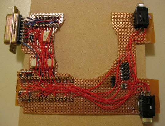
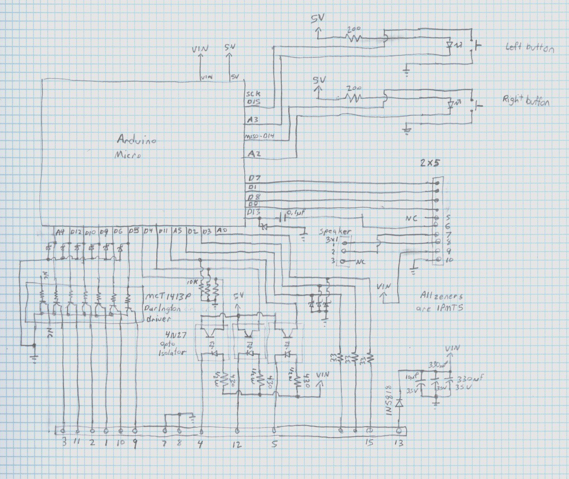
05/28/2014 at 12:29 • 0 commentsThe added circuitry is reasonably simple, mostly just a bunch of IO with lots of protection. Features were put in place to protect against damage due to electrical spikes or static discharge. This is especially important given that in this application, I expect to have 50ft of wiring connected to some of the IOs, and wanted to be able to support larger lengths.
![]()
![]()
Six of the arduino lines run past 5V zener transient voltage surpressors. I am using 1PMT5 devices because I had a bunch scavenged from another board, and they are really good devices, if not the most convenient package. Past these, they run to the base inputs of a darlington open collector driver chip, an MC1413, again used because I had a couple on hand scavenged from something else. The collector pins run to the DB-15(bottom in schematic). These will serve as the primary outputs for driving relays, etc. The open collector choice was intentional as it means the different outputs can be pulled to different voltages depending on the need.(ie, could use 5V, 12V relays or other loads) 4 of these are on PWM pins in case that feature is ever desired.
Three of the arduino lines are connected to 4N27 opto isolators to serve as the primary inputs. Given the high isolation already afforded by these, I didn't bother with the TVS's. The other side of the opto's have the led anode connected via resistor to the power input, and the cathode to the DB15. This allows the external input to simply switch this pin to ground to activate the input. The resistor is a 430ohm, 1/2W, chosen to allow functioning within specs of the opto, for the entire 8-20V power input range.(at 8V, this is 13mA minimum, and at 20V is 32mA.
The UART pins of the 32u4 are wired to the philips uart to communicate with the keypad and lcd.
Two pins were wired to the RS232 level converter. Pins chosen to have the pin change interrupt capability on the RX. This will allow a software UART to run on the arduino out the connector on the bottom of the controller if ever desired.
The I2C lines(D2/3) were wired past 5V TVS's, through 33ohm resistors and to the DB15 as a possible expansion for the future. The resistors will have negligible affect on the slow edge rate I2C, and better allow for any possible surge dissipation. No pullup was added to allow 3.3 or 5V operation supplied by the slave device(s).
One PWM output is wired past a 5V TVS, and through a 0.1uF ceramic capacitor. This feeds into the hand paddle board. The paddle already had an output of the philips microcontroller feeding through a capacitor into a FET which drives the speaker. The output of my capacitor will also be tied into the FET gate, which will allow either microcontroller to drive it. The purpose of the zener is to take positive and negative spikes which will result from this arrangement. It is a bit redundant because the 32u4 already has protection diodes on it's ports, but better safe than sorry.
Two pins connect to the installed arm/firing buttons, and two more wire to the LEDs built into those buttons.
One of the analog inputs is wired past a 5V TVS, through a 33ohm resistor, and to the DB15, again as a possible future expansion.
I took care to not create conflicts with the SPI port, leaving MOSI and SS unconnected and MISO and SCK only connected to the pushbuttons. As the pushbuttons are NO, as long as the buttons are released, the SPI port can still be used for programming the 32u4.
DB15 pinout was chosen to provide 2 grounds, with the analog signal between. It and the I2C channels are also separated from the darlington outputs and opto inputs by the power line, also for a bit of shielding.
A 2x5 header(center right in schematics) was mounted to create a removable connection to the original circuit board in the controller. A 1x3 header was placed to relocate the speaker connector as the original location on the original board took up too much height and prevented my board from fitting.
I used mostly surface mount parts because I find them so much easier to fit into projects, and they really are not much harder to use. Especially resistors, with the common 0402-0805 sizes easily bridging between two 0.1" spaced pads, taking up practically no additional space, unlike leaded resistors. This was also very useful here as the back of the circuit board needed to remain completely flat to fit into the case, which only had a thin space for me to work in. Everything is topside placed and wired.
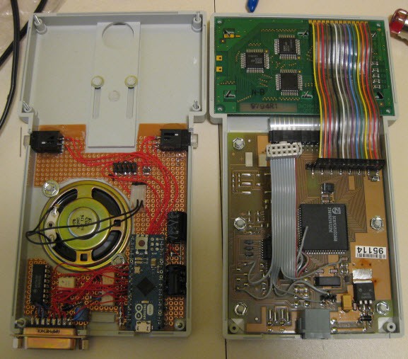
A ribbon cable segment was wired into the appropriate points on the backside of the original controller, with a 2x5 conector to mate with the new board. Here are both boards, mounted in both halves of the case, ready to be closed up.![]()
I also added a local decoupling cap on the original controller board at the input, at the input of the DB15 connector(after protection diode), as well as a pair of large capacitors on the right which serve as a quick hold up in case of momentary power loss. -
Controller Modifications
05/13/2014 at 16:45 • 0 commentsI probably could use the paddle board pretty much as is, and reprogramming the existing SC87C451 microcontroller. There look to be extra GPIO pins available that I could use for my other required inputs and outputs. That said, I don't have the tools(compiler or programmer) for doing it, and given my time constraints, am not particularly interested in re-inventing the wheel. I tend to be more of a hardware person than a software person, so anything that makes software easier, I usually go for.
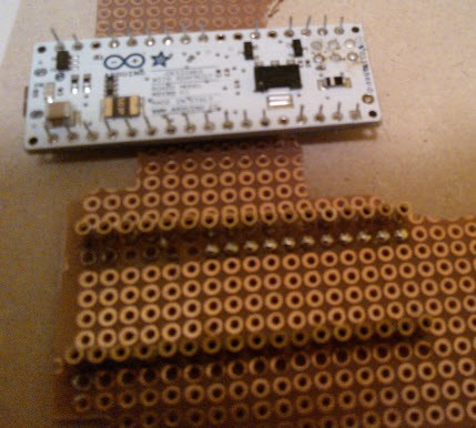
In this case, I'll leave most of the original circuit intact, add a new microcontroller, and simply have it communicate via serial. Given my aforementioned preference for simplifying software, and desire for getting this done quickly, I'll go with the arduino environment and bootloader on an AVR. Digging through the available boards, I settled on an Arduino Micro, as it allows me to use it's hardware UART to connect to the SC87C451, while still leaving the USB port for development, or any other future purpose.
It occurs to me that this sort of controller may be useful in a lot of other situations than just this one, so I'll endeavor to include extra features and make things more flexible where it's reasonable.
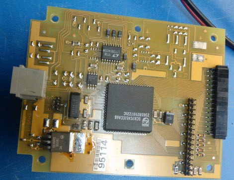
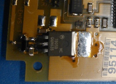
The first modification to the original circuit board is to convert it to run on 12V. I wanted to do this because it is far more robust to feed a semi-unregulated 12V into this than a regulated 5V. Using a DPAK2 7805 linear has plenty of capacity to power both the original circuits as well as the micro. As mentioned before, There were already pads for a 7805, so I soldered one down(hot air rework to get a good thermal pad solder joint), and included a diode to prevent reverse voltage across the regulator(I know the datasheets say this is only required for higher voltage, but I've had these fail, and there were already pads to place it). I didn't have a surface mount one, so just used a leaded one, with the leads bent back and trimmed off as shown in the picture.![]()
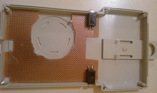
Next I moved to the rest of the case for adding the extras I needed. I decided to use add a circuit board to the inside of the back panel, with all top side connections. This paddle is rather thin, at only 3/4" thick, which means I need to be careful to get it to actually fit. I normally use through plated perf board for my circuits, but had a couple single sided perf boards sitting around I never used. Given that this is all top side work, I figured I could use one of those up. This sorta turned out to be a nuisance because it isn't an FR4 board, instead a phenolic board(FR2). I miss my FR4 already, but it's ok, and will work fine. I used a rotary tool(dremel) to cut out a piece that would fit in, and attached using the existing zip screws that held down the speaker on the back panel. I also cut out space to mount a couple lighted pushbuttons so that they could be flush with the back panel. These were mounted by soldering two of the leads directly to the PCB, and epoxy applied to the edges(after sanding the surfaces) to re-enforce. I cut notches in the sides of the case for the buttons. I think this mounting will be sufficiently mechanically strong to take a lot of hard presses without breaking loose because they are backed up by the PCB itself. These buttons will form the two buttons for arming and firing the system. I'll use the LEDs to indicate arming state.![]()
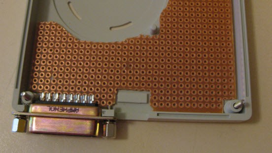
Next came mounting for an additional connector to serve as the system inputs and outputs. I opted for a DB15 as it just fit in the bottom, and is relatively easy to get additional connectors for to be able to use the controller in other applications. I notched out the plastic with the rotary tool, and fastened it by drilling pilot holes, and taping them for 4-40. A standard set of screw/standoffs(not sure what these are actually called) was then threaded into the tapped holes to hold it in place, and allow the connecting cable to be screwed in if desired.
![]()
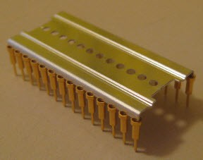
The last case modification comes from the opening for the Micro USB connection of the Arduino Micro. I opted to socket the micro. I did this by using single pin sockets, soldered to the PCB. This allows wiring to go underneath the Micro. A pin socket is what is used in the nicer IC sockets, just without any sort of plastic frame. They come on a metal mounting frame that is used to align and hold in place during soldering, then the mounting frame is removed. I ended up with a large stash of these(probably diving again) so use them frequently. They accept IC pins, not the larger header pins, so I used an Arduino Micro without headers, and soldered in short lengths of steel wire as pins.
The pin sockets in mounting frame:![]() In place, next to the Micro:
In place, next to the Micro:![]()
With the Micro mounted, I simply cut a notch in the case for the micro USB cable.
I mentioned that the paddle is pretty thin, so it was a tight fit to get things in there. Though I ordered the Micro without headers, it still comes with the ICSP header. Many people struggle with desoldering headers like this. I don't like solder wick on through plated holes as it never seems to get everything off. I frequently use hot air rework as my go-to desoldering, but given the small board, I opted to go with the more simple method. The plastic frame that holds a pin header together is not very high temperature. Because of this, if you don't need the header, you can actually just remove one pin at a time. Use an iron to heat up both ends of the pin for a while. Not only do you need to melt the solder in the hole, you want to partially melt the plastic frame. Using a pair of needle nose pliers, you can then simply pull the pin out of the hole and frame at the same time. When you remove the last pin, the remnants of the frame come with it. A good board stand helps with this. -
Controller and reverse engineering
05/08/2014 at 15:42 • 0 commentsI need a controller which can implement the required sequencing, implement the positive manual enable, and a lock system to prevent unauthorized use. A convenient way to do testing while adjusting parameters would also be helpful.
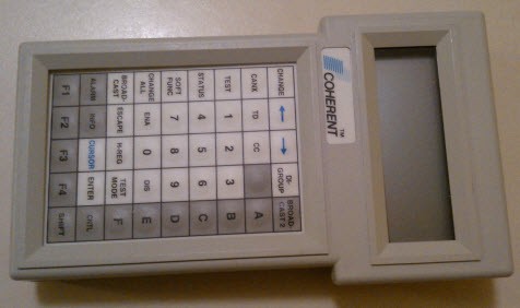
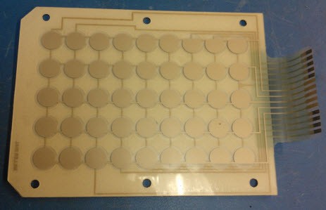
Digging in my parts bins I had hand paddle which was originally used with some sort of networking equipment. Not sure where I got this, but probably from a little dumpster diving. When I got it, I opened it up, and was glad to see that it used a common HD44780 LCD module, instead of integrating the LCD controller into the main electronics, so I knew it would be a good starting point to hack.![]()
Initially I figured I would just replace the control electronics in it, wiring the LCD and membrane keypad to a controller of my choice, but I decided to do a bit more poking around. It was pretty easy to reverse engineer the circuit, and identify the connector pinout and power requirement which I didn't know and couldn't find on the web.
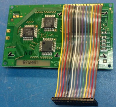
The insides:
![]()
![]()
![]()
(The main circuit board has only top side placement so the bottom is completely flat, as it forms the mechanical backing to the membrane keypad.)
A Linear Tech LT1281 is connected to the RJ11, and is a RS232 level shifter. For lines are connected. The main component on the board is a Philips microcontroller, SC87C451. From it's datasheet, it is easy to identify the UART RX and TX which connect to the LT1281. This allowed me to identify which of the RJ11 pins is TX and RX. The other two go to GPIO, and presumably are for RTS/CTS. Again, using the LT1281 datasheet identifies which is which.
The other two pins were power and ground. Ground was easy to identify and traced back to the ground pins of the devices. The power line went over to an area of the circuit board which was mostly unpopulated, but had a 0 ohm resistor place to connect it to another fill, which could be traced back to the 5V pins on the components.
Wiring up a RJ12/25-DB9 adaptor, wiring in 5V, and powering it up seemed successful. Pressing keys resulted in characters in a terminal window, and sending from the terminal window resulted in characters displayed on the LCD, however all quite garbled. I tested a bit with different baud and bit settings, without success, then just put a scope on the TX line out of the paddle. This confirmed 9600 baud, though it took a bit more analysis, and different button presses to determine that it is using an uncommon configuration, with 7 data bits, even parity and 1 stop bit. Switching the terminal over to this, and it worked much better. Characters sent were displayed on the LCD, and button presses on the keypad had mostly reasonable bytes sent back. I used RealTerm in debugging, which was a fabulous help as not all the button presses were printable characters. I had never used it before, but in the past occasionally had need for serial terminal program which supported other binary transactions. RealTerm was perfect! I went through all the keypad presses and came up with the mapping of which buttons send which bytes, including the shift and control versions. They mostly don't make sense to what the keypad is labeled, but it doesn't matter because I can just use the mapping in my program.
Given this, the paddle is actually usable pretty much as is, just needing an additional controller, inputs and outputs.
Digging around the rest of the card shows a large unpopulated section in the upper left which is presumably intended for an inverter to power an EL backlight for the LCD.
Just above the RJ11 are pads for some sort of surge device. At the left edge are pads for a surface mount SIL header with pins for power, ground, and RX/TX. There are also pads which would allow the placement of 0 ohm resistors instead of the LT1281 level shifter which would make it 5V communication on the RJ11. On the lower right was placement for a standard 7805 linear regulator in a DPAK2 package. In the above picture, I've already removed the 0 ohm jumper and placed a 7805 to convert the board to run at 12V. -
Sourcing Components
05/06/2014 at 13:46 • 0 commentsA number of the parts used in this project are hard to acquire, specifically the regulator and solenoid valves. After much scouring, I decided to place an order for the harder parts from Poofer Supply and I was extremely pleased with them. I ordered the 100psi regulator, the 3/4" solenoid valves, the POL fitting, pressure gauges, LP hose, and several fittings. Not only were they very quick, they quickly replaced a gauge that broke in shipping, and their pricing was actually equal to, or better than anywhere else I could find parts. Plus, they are a small business supporting the maker community(fire arts specifically).
As I noted in an earlier post, some of the 1/4" black pipe fittings were a bit hard to source locally, though I did end up finding everything by going to a number of home centers. I'd recommend finding all the pieces you need in advance, so you can add the other fittings you cannot find to your orders. I had figured that local would be cheaper, but turns out I was wrong.
The only note I had about poofersupply is that their website order processing didn't seem to work under firefox. I had to use another browser to actually place the order.
The HSI I ordered from a supplier on Amazon, though you may be able to source locally from a HVAC supplier or repair company.
Most of my electronics components I had in parts bins, etc. I did order an Arduino Micro and large push button from Adafruit(a fantastic company). I will likely order the keyswitches from Sparkfun(another fantastic company). -
Initial testing
05/05/2014 at 23:11 • 0 commentsI took out the setup for some initial testing. This is using the manual controls, not the controls which will implement precise sequencing. First steps were to connect it all, and open the pressure on the LP tank(but not the inlet to the accumulator), and use the leak detect fluid to check for leaks on the joints I couldn't test before. No leaks found. (Overall, the 1/4" connections didn't seem to have any issues, it was the 3/4" ones that were harder)
Testing was done in a wide open area with a slight breeze.
At this point, the accumulator has atmospheric air because I used a standard air compressor for leak testing. This is problematic because adding propane will result in a mixture of propane and oxygen. This means that the propane could ignite inside the accumulator and explode. Normally this isn't possible because with just propane and no oxygen, ignition cannot happen. One of the reasons the air fitting was added was to purge the tank with an inert gas, such as CO2, Nitrogen or welding shielding gas. Though commonly available at welding shops, brew-n-grow places and beverage supply houses, I don't yet have a tank of this, mainly because I need to purchase a tank and regulator.
Instead, given the location, I purged with the propane itself. I did this by filling the accumulator, then venting it with the ignitor off so ignition wouldn't happen. I did this a couple times, waiting a bit between each for the propane to dissipate. In the future I will need to get a tank of gas to purge, because I'll want to purge the propane out of the accumulator for long term storage and transport.
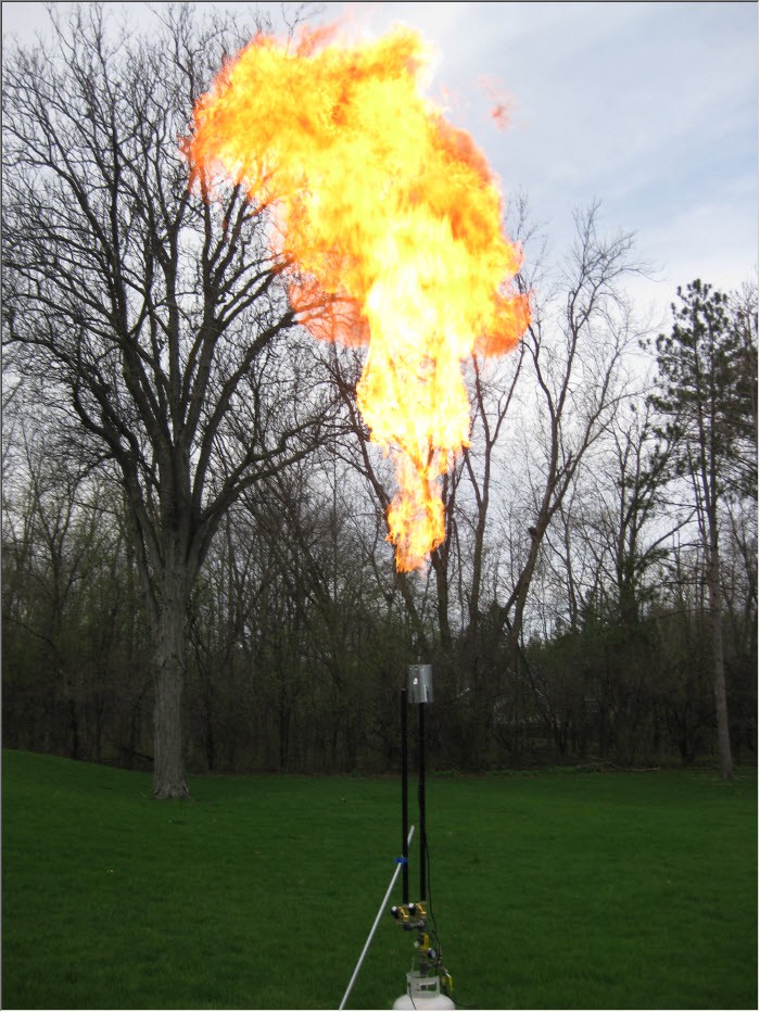
I turned on the HSI and gave it a couple minutes to heat, and let a test fire go, nothing. But second try was a success! (I guess the HSI wasn't hot enough the first time)![]()
This picture was taken in daytime, and is a 1/160sec exposure just manually pressing the shutter release a moment after hearing a helper pushed the button. That is, this is not a long duration exposure. The top of the flame is 15-20ft high.
I spent a while experimenting with different timing, different pressure, and sequencing the two barrels. The second barrel prelaunched without ignition definitely helps create more fireball at lower pressure, and a better effect. I never got above 35psi as the LP tank was down to that by the time I got up to that pressure; it was mostly empty at the start anyway.
It is a very impressive display, and definitely puts out quite a bit of heat from 20ft away. Running the calculations, given the Cv value of the valve used(7.6), the specific gravity of propane(1.52), and the average energy density of propane(2516 BTU/ft^3 as a gas), a 1 second burst is about 6500 BTU. This is obviously a burst type device, but that would equate to 23,000,000 BTU per hour. (A 2500ft^2 home might have a 100,000 BTU furnace) Flow through the regulator is estimated at a bit less than 1/10 of that, so it would take 10-15 seconds to repressurize the accumulator after a 1 second burst. During testing, it didn't seem quite that long to repressurize, but it was at least reasonably close.An LP tank usually cannot sustain that sort of flow because the propane will freeze in the tank. After about 15 min of testing (maybe 80 bursts), it did start to freeze as rocking the tank revealed the tell tail signs of slush inside. The outside of the tank was forming ice. This was probably exacerbated because the tank was very low. Some other large projects using this type of system will actually heat the tank with a hot water bath to prevent this, though in my use case it shouldn't be a problem. It may just limit how much testing I can do in a given session.
I will continue working on the sequencing controller, and get the LP tank refilled for testing next time to determine the desired timing, and trying out higher pressure. -
Ignitor
05/05/2014 at 18:58 • 0 commentsIgnition is handled using a Hot Surface Ignitor. These are frequently used in modern gas driven furnace's and hot water heaters, and are available on the parts market, around 30-50 USD. Simply power them to rated voltage(some are 120VAC, some I believe are 80VAC), and they will heat up glowing red hot. The surface will exceed the ignition temperature of propane, so when propane and oxygen contact it, they will ignite.
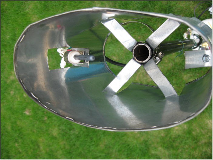
A shroud was made with a length of galvanized steel ducting to mount the HSI. The shield serves to protect the HSI from the wind, which may cool it faster than it's heater can add heat.
I just tabs into the duct to mount the HSI, and other tabs to form a mounting on the barrel. It is attached to the barrel using a simple pipe clamp. The HSI is screwed in with a sheet metal screw using it's mounting tab.
![]()
I made tabs on both sides so that a redundant HSI could be used. I understand these are fragile and prone to breakage, so I wanted a backup. The second is not mounted at this time. I used the included ceramic wire nuts to connect the HSI leads to an AC line cord. In testing, flames occasionally swirl around the shield when low pressure releases happen, in the area of that line cord. For extended usage, high temperature wire should be used. I will monitor how the standard PVC line cord does, and replace if needed.
The HSI is mounted just at the edge of the gas flow out of the opening in the pipe, and about 4" up. In testing, this position occasionally did not ignite when running at higher pressures. It may have to move higher up, or more into the stream.
I bent and hammered over the top and bottom edges of the ducting to reduce sharp edges.
-
Electrical for testing
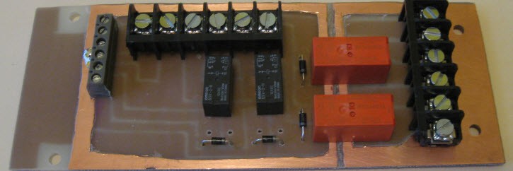
05/05/2014 at 17:11 • 0 commentsIn the prior post I discussed the plumbing. At the bottom of the first picture were two boxes. The black one at the base of the accumulator contains connections and relays to remote control the system. I knew I needed remote control, and there are a lot of ways of implementing such. Wireless is an option, though it complicates things, makes it less reliable, and has some added risk for incorrect behavior. Given the safety issues, it is unmost important to not have accidental firings. For this reason, wired connections are used. Further, when using log wires, they can serve as antenna, and random spikes can occur. To prevent this from causing problems, activation of elements requires a steady non-trivial current. For robustness, I opted to just use relays in this box for switching the hot surface ignitors, as well as the solenoids. I was initially concerned about time delay's introduced by using relay's on the solenoids, but I quick tested the ones I was looking at using on a scope, and with a 4ms switching time, really shouldn't have any realistic effect. There is already going to be a delay in the solenoid anyway.(I couldn't find the spec for this model, but it looks like 50-200ms are reasonable values for this size) The relays require about 100mA to activate, coupled with the inductive nature and slow operating time should prevent any electrical noise from accidental triggering.
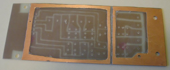
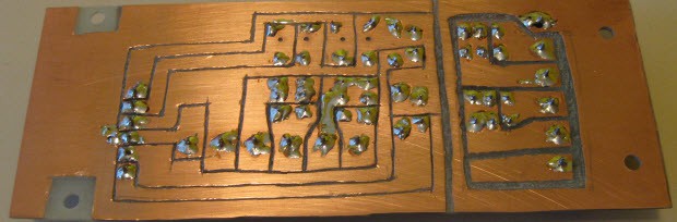
Normally I wire my circuits on through plated perf board, with point to point wiring. With this circuit, I decided it was a good opportunity to hand route a PCB as there are few traces, some are higher current, and the larger terminals are not on 0.1" spacing anyway. I did this with a blank double sided copper clad board, and a rotary tool(ie, dremel) to isolate traces, and peeled off larger sections of copper as needed, and component pin holes drilled on a drill press. The result, though very rough and crude turned out great, and was quicker to do than it would have been to draw the schematics and layout.
![]()
![]()
As I only had double sided clad, I simply created ground rings on the topside. This way if there is a short with the AC side, it will hopefully short to the ground and blow the breaker instead of shorting into the low voltage side. Note the isolation moat between AC and low voltage sides. AC side is grounded to earth through the AC cord. Low voltage is not grounded.
The circuit is easier to follow soldered up:
![]()
Relays are simple 12VDC. The black ones rated for 3A @ 30VDC, and the orange ones for 15A @ 120VAC. Flyback diodes were installed to keep noise down, protect the controller, and make for quicker opening of the relays. The footprint was made to support the larger relays in the place of the smaller ones in case I ever wanted to change them.
Terminals on the right are for AC ground, neutral, and relay contacts. These serve to switch the AC outlets that the hot surface ignitors are plugged into.
Terminals in the middle are for 12V power for the system, and relay contacts. These relays are for switching the 12V solenoids.
Terminals on the left are for wiring to the remote.
Bottom side, nothing exciting here.
![]()
That board is pretty much all that is in the black box.
The grey box at lower left of the image is a project box I had sitting around which already had 5 switches mounted in it. I simply replaced two with buttons, and wired it to be a quick and dirty manual control system for testing while I finish the final controller. One switch serves as an enable for all the others, two control the AC relays, and the two buttons control the solenoids.
The last bit of electronics are in the wire leading from the black box up to the solenoids. I installed flyback diodes for these in the middle of the wire. I wanted to keep them closer to the solenoids, but didn't have a robust way to mount them closer. So I soldered them in the middle of the line, protected with heatshrink, put a couple steel wires in parallel(to avoid bending which can break solder joints), and another layer of heat shrink. These are very large solenoid coils, drawing just over 1A at 12V, and again, I wanted them to de-energize quickly.
-
Plumbing
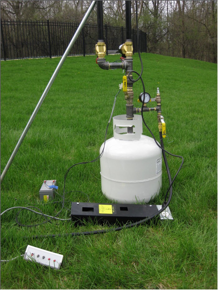
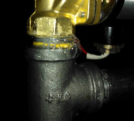
05/05/2014 at 16:04 • 0 commentsSeveral pictures of the nearly finished plumbing. The first is of the accumulator tank end:
![]()
The accumulator tank is at the bottom. I sourced a new, purged and never used LP tank from the hardware store to remove worries of residual propane when removing the fitting. The normal fitting must be removed because we require vastly more flow from this tank than it can provide. Though it is a standard 3/4" NPT threaded fitting into the tank, it is glued in. In the end, I constructed a version of a "propane tank valve wrench" out of a 6" segment of 3" black pipe. I crudely cut out notches on both ends with an angle grinder. Had I realized that this type of wrench is easily available online, I might have purchased one instead of constructing. I used a truck tie down strap to strap the tank to a long large board, and a segment of pipe to turn the valve. I used a heat gun on the tank near the valve(not on the valve; metal expands when it gets hot), and with probably 200 foot pounds of force it turned.
Above the tank is a collection of fittings, nipples, T's, etc to make all the connections. The main flow path is linear with no bends to facilitate maximum flow, and is all done with 3/4" black iron pipe. Black iron is required for gas use, and is rated for LP. All connections are threaded, and sealed with yellow teflon tape as required for gas use.
A 3/4" ball valve is included above the tank and functions as the manual shut off valve. With this closed, gas cannot be vented, no matter the state of the solenoid valves. A ball valve is used for maximum flow, and quick shutoff. Above this, is another T, and the two solenoid valves(brass) which lead to the barrels. The solenoid valves must be rated to support LP gas as it is semi corrosive to seals. These have Viton seals. The barrels are about 4ft long so that all added together the exit aperture is just above most people's head height.
Split off the main pipe from the tank, is an area using 1/4" pipe. 1/4" can be difficult to get, so check your suppliers before assuming you can get it locally. Attached on this branch is a gauge to show what pressure is present in the tank. I used a 200psi gauge per recommendation that it should be double any working pressure. I designed to work up to 100psi, though I don't think it will ever be used that high. I probably should have gone with a 100psi gauge for better scale granularity.
Past this are two fittings with ball valves isolating them. One goes to a 3/8" flare fitting for the LP hose, and the other to a standard tool air supply fitting. The flare fitting is for the input. The air supply fitting is for pressure and leak testing, as well as to purge the tank.
All ball valves are oriented so that when closed, they are less likely to be bumped into an open position.
The angled silver colored pipe is a stake, which is being used as a precaution so that the system won't tip given the uneven grass.
I'll cover the electrical elements separately.
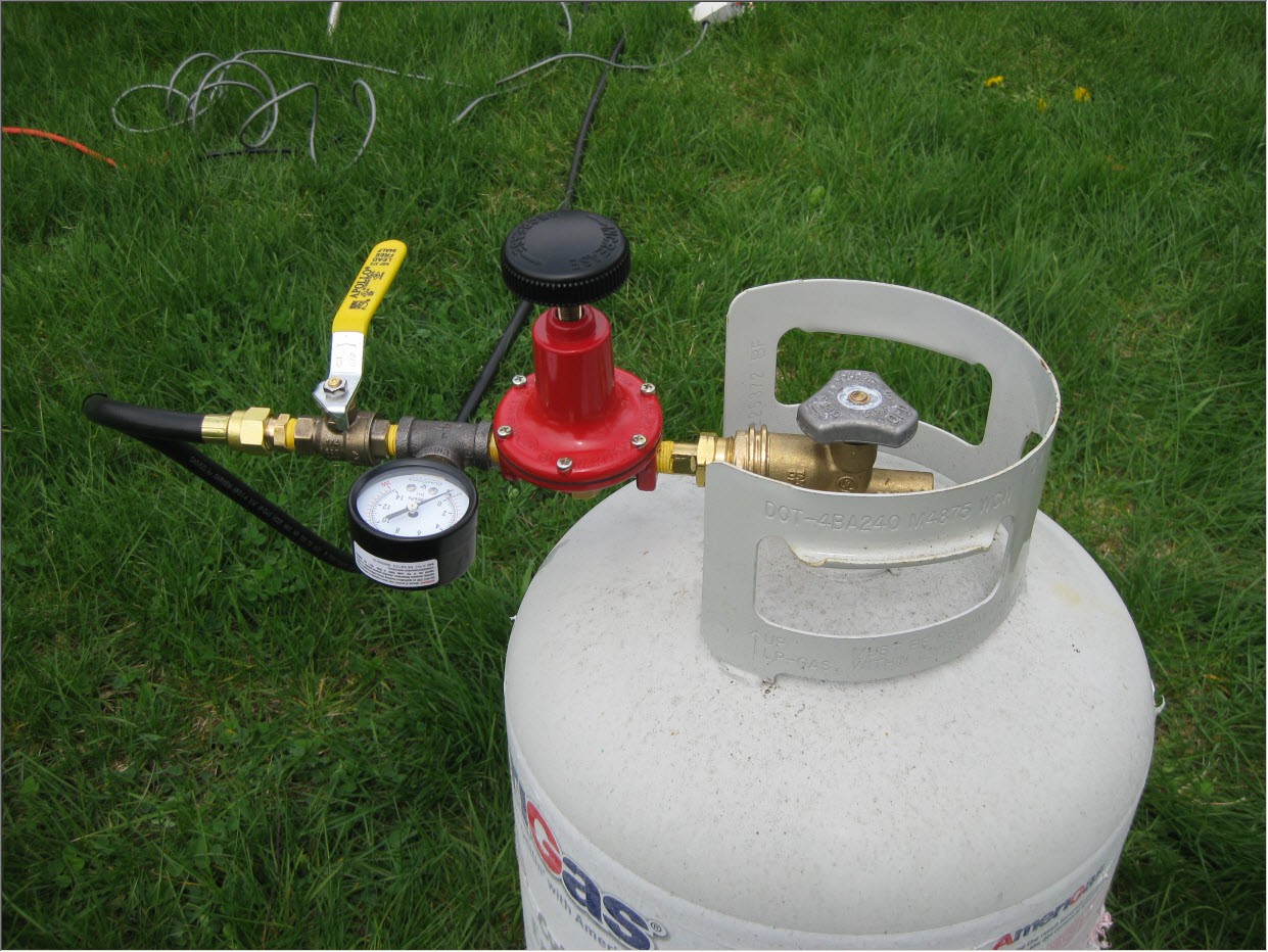
The second picture is of the source tank end:
![]()
This is a standard, full LP tank. Connected to it is a full bore POL fitting. The large hand screw type fitting used on a grill has limited flow, and we require about 10 times that. a POL fitting screws into the inside threads with a reverse threaded nut.(counter clockwise to tighten)
The POL fitting is connected to a high pressure regulator. This is a harder part to source as most regulators have several up to maybe 20psi. In this application, I needed to support higher than this. I chose a 100psi model, though a 60psi probably would have been sufficient. Again, this regulator must be rated for LP gas.
Past this is a gauge to show the regulated pressure. And past this is a ball valve, and another 3/8" flare fitting for the LP gas hose. The hose must be LP rated.
When all connections were made, I used an air compressor to pressurize the system at 100psi, and gas leak detect fluid to check for leaks. This is the first time I've done this many threaded connections, as well as the first time I've done gas, so I will take it as a relatively good job that out of 28 connections, only 2 leaked. I removed, cleaned off, and re-taped and fitted them, and resulted in no leaks. I've always heard the idea of using soapy water in a spray bottle, but I have to say this lead detection fluid is way better. It really stays on the joints for an extended time, and makes easy to see bubbles.
![]()
It cleans up easy by just wiping with a paper towel.
With leaks gone, I left it pressurized for several hours, with no change to the gauge reading.
Note that I could not test the connections between the POL fitting and the first valve after the regulator. The regulator does not hold pressure backwards. For those, I tested the connections using the LP tank later.

 In place, next to the Micro: