April 19, 2016 by Naim Hilal
HW update time! Been working on selecting components for our device. As a general rule of thumb we tried to pick parts that are:
- Easy to get (in stock)
- Operate on a common voltage
- Use common communication protocol
- Hand solderable package
- Documentation and sample code (for our sanity!)
- Low in price
We want to keep the design simple and low cost, while it is easy to build. Unfortunately, these don’t always go together, especially with market trends with phones and wearable devices becoming smaller. The market demand drives the cost of small components down, but they are not hand solderable! So we have to find a good balance for each part.
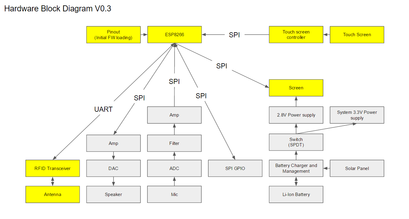
As for the Minimum Viable Product (MVP), we believe that the user should be able to send and receive text messages. Therefore, we need an input device (touch screen), output (screen), and a mean to send/receive messages (WiFi and RFID). These components are highlighted in yellow in V0.3 of the HW Block Diagram below:
The centre of our design is the ESP8266-ESP12. It is the main processor and WiFi module (USD $2.50), it operates on 3.3V and support SPI and UART. So we wanted to set our system voltage at 3.3V and use SPI for communication (because it’s supported by the screen).
For a screen, we found a 3.5” TFT LCD which comes with a resistive touch panel for a low price (USD $9.63). The screen is powered on 2.8V, which will require a dedicated DC-DC converter. Although it adds complexity and cost, it also offers an easy way to control the backlight of the screen. As for the touch screen controller, the TI TSC2046IPWR (CAD $2.30) can run on 3.3V, hand solderable (16-TSSOP), and uses SPI.
As for the RFID, we couldn’t find something that was low cost and uses SPI. So we opted for the Panasonic MN63Y1210AF (CAD $3.54). It runs on 3.3V and uses UART, which is supported by the ESP8266. As for an antenna, the Taoglas FXR.05.A (CAD $4.10) operates on the same frequency of the NFC chip (13.56MHz). This antenna is for the desktop prototype only, we intent on having the antenna etched on the PCB in the final version.
We chose to focus on the above parts for the desktop prototype. Non essential parts that we looked at/noted:
- Mic and Speaker signals will need to be have filters and amplifiers, we skipped it for now.
- We may need a GPIO expander for additional inputs to the ESP8266
- This solar panel (USD $2.95) is close to the screen in dimension and will fit nicely on the back of the device mechanically
- Li-Ion Batteries: 4000mAH (US $5.31) and 1000mAH (US $4.41 for a pack of 2)
- Battery charging and management: Microchip MCP73871 (CAD $2.50) has an Adafruit dev board with great features, though not hand solderable.
- Li-Ion battery’s voltage will drop lower than the system 3.3V, so we will likely have to use a Buck-Boost supply 3.3V rail. We are considering the LT LTC3530
 naim.hilal
Discussions
Become a Hackaday.io Member
Create an account to leave a comment. Already have an account? Log In.
You probably don't need a boost converter. If the battery's voltage is 3.3V, there's probably very little energy left in it. Check out the LiPo discharge curves.
Are you sure? yes | no