-
UPDATE 5: HW Selection and MVP
04/20/2016 at 01:25 • 1 commentApril 19, 2016 by Naim Hilal
HW update time! Been working on selecting components for our device. As a general rule of thumb we tried to pick parts that are:
- Easy to get (in stock)
- Operate on a common voltage
- Use common communication protocol
- Hand solderable package
- Documentation and sample code (for our sanity!)
- Low in price
We want to keep the design simple and low cost, while it is easy to build. Unfortunately, these don’t always go together, especially with market trends with phones and wearable devices becoming smaller. The market demand drives the cost of small components down, but they are not hand solderable! So we have to find a good balance for each part.
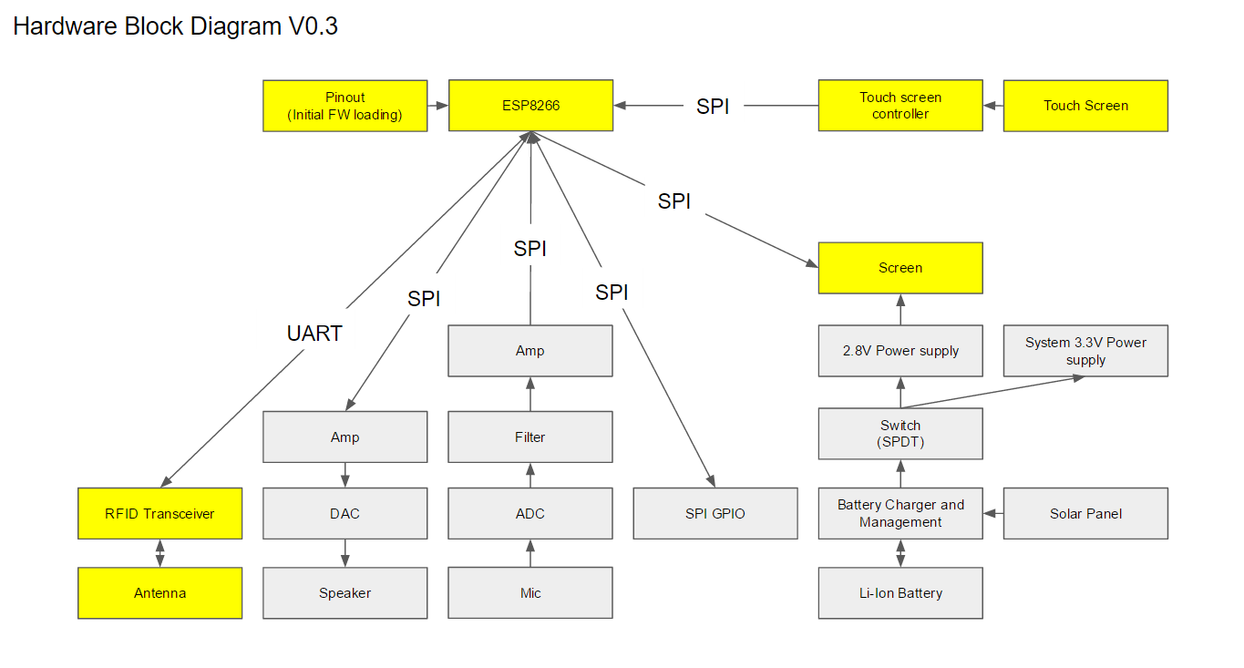
As for the Minimum Viable Product (MVP), we believe that the user should be able to send and receive text messages. Therefore, we need an input device (touch screen), output (screen), and a mean to send/receive messages (WiFi and RFID). These components are highlighted in yellow in V0.3 of the HW Block Diagram below:
The centre of our design is the ESP8266-ESP12. It is the main processor and WiFi module (USD $2.50), it operates on 3.3V and support SPI and UART. So we wanted to set our system voltage at 3.3V and use SPI for communication (because it’s supported by the screen).
For a screen, we found a 3.5” TFT LCD which comes with a resistive touch panel for a low price (USD $9.63). The screen is powered on 2.8V, which will require a dedicated DC-DC converter. Although it adds complexity and cost, it also offers an easy way to control the backlight of the screen. As for the touch screen controller, the TI TSC2046IPWR (CAD $2.30) can run on 3.3V, hand solderable (16-TSSOP), and uses SPI.
As for the RFID, we couldn’t find something that was low cost and uses SPI. So we opted for the Panasonic MN63Y1210AF (CAD $3.54). It runs on 3.3V and uses UART, which is supported by the ESP8266. As for an antenna, the Taoglas FXR.05.A (CAD $4.10) operates on the same frequency of the NFC chip (13.56MHz). This antenna is for the desktop prototype only, we intent on having the antenna etched on the PCB in the final version.
We chose to focus on the above parts for the desktop prototype. Non essential parts that we looked at/noted:
- Mic and Speaker signals will need to be have filters and amplifiers, we skipped it for now.
- We may need a GPIO expander for additional inputs to the ESP8266
- This solar panel (USD $2.95) is close to the screen in dimension and will fit nicely on the back of the device mechanically
- Li-Ion Batteries: 4000mAH (US $5.31) and 1000mAH (US $4.41 for a pack of 2)
- Battery charging and management: Microchip MCP73871 (CAD $2.50) has an Adafruit dev board with great features, though not hand solderable.
- Li-Ion battery’s voltage will drop lower than the system 3.3V, so we will likely have to use a Buck-Boost supply 3.3V rail. We are considering the LT LTC3530
-
Update 4: Software Progress, UI and auto-updating
04/18/2016 at 00:08 • 0 commentsApril 17, 2016 by Ilia Baranov
Software update time! Been working on getting the basic backbone of the software working, and so far things have been going really well. Things we have learned this session:
- No need for public-private keys. They are slow to compute, complex, and don’t offer much benefit over a shared secret in our application. Thus, we are using AES 128, and it can do one encrypt-decrypt session (64 bytes of data) in 749526 cycles. This is (at 160MHz) 4.7ms.
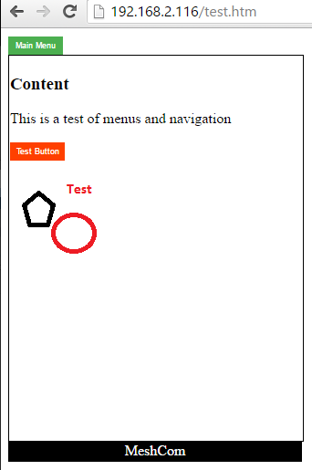
- Make the UI easy to use. After a lot of flailing, we settled on using HTML (with javascript + CSS) as our rendering engine. This means that developers can just write the interface in normal HTML, and that gets us an easy way to render buttons, images, etc. This means we can get this working right now, with a laptop, without waiting for hardware components (screen, etc). Downside is: We will have to write an HTML rendering engine to display the data on the built in screen, which will be tricky, but reasonable if we target a small subset of HTML features. Here is what it currently looks like:
- ESP8266 works really well with mixed AP and client mode, and is able to do non-disruptive scans. This means the device can do mesh network in a fairly reliable way.
- Being able to upload updates to firmware and content over the air is CRUCIAL. The serial updating is slow, and un reliable. The code is made to auto-update via a webpage.
- The ESP8266 SPIFFS system is really nice! Easy to use, easy to update.
Over architecture for system startup now looks like this:
- ESP8266 boots, loads Meshcom firmware
- Starts AP mode, tries to connect to wifi (for testing, updating, timekeeping)
- Shows user HTML page, asks for login details
- When user sends message, uses shared key, encrypts, and sends TCP packet with header info (containing device data, target, TTL, etc
- Background functions (using the timer library) routes other packets, updates public info, etc.
Code has been updated, and contains some helpful functions (for Windows) for auto updating content, etc. Check it out! https://github.com/meshcom/software
-
Update 3: Hardware Block Diagram
04/01/2016 at 02:47 • 0 commentsMarch 31, 2016 by Naim Hilal
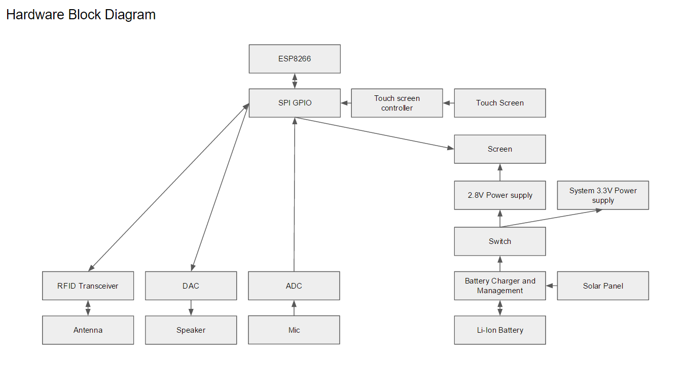
The hardware design is centered around the ESP8266. This chip is low cost, high bandwidth, flexible, and is fairly powerful. Communication is transmitted primarily through the ESP8266 (WiFi) with RFID as a backup. The device features a touch screen, microphone, and speaker. The Li-Ion battery can be charged via USB or solar panel, powering two power supplies, 3.3V system power and a 2.8V for the screen. SPI is used as the primary serial communication interface between peripherals with a GPIO to expand the pinout of the ESP8266.
-
Update 2: Software Architecture
03/28/2016 at 00:38 • 0 commentsMarch 27, 2016 by Ilia Baranov
Here is a general outline of software flow for SMAC. Ideally, the user interface will be written as html pages that the ESP8266 is able to render to the on screen display. Ideally, leveraging the great work done by the ESP8266/Arduino group means less library writing for us, though a basic HTML interpreter will be an interesting challenge. That way, they are easy to write and edit, and can be loaded and accessed from a computer during the software update phase.
Join the software update next time for details on the communication backend, reputation system, and more!
-
Update 1: Jamming/Infrastructure Independency
03/23/2016 at 01:20 • 0 commentsMarch 22, 2016 by Naim Hilal
Let's start with Jamming/Infrastructure Independency. The device uses a mesh network topology where every message sent from each device is packetized and routed by any available route. This protects against a centralized take down or disabled cell infrastructure, and is somewhat resilient to jamming, as it can route around trouble areas, but it is not totally invulnerable.
To make the device almost invulnerable to jamming, we turn to the backup RFID sneaker-net system. In heavy jamming situations, users would touch devices together with all their closest neighbors, thereby passing on messages like nodes in a network. For instance, in a large crowed, we estimate that roughly 10 hops will get the message across the crowd, so as long as people tap devices ~10 times a minute, communication latency would be fairly low. To prevent messages propagating for ever, TTL hop limiting would be used. The power requirement of jamming near range, shielded (by the interlocking bodies of the device) RFID communications would be so large, they are well outside the range of conventional or military hardware.
Passing messages via RFID is a little clumsy and slow, but in the event of Jamming, it is the only way to ensure message delivery. Also, in more social uses, passing messages only via direct contact has an element of interactivity.
Secure Mesh Async Communication (SMAC)
A low cost communication device, similar to a tablet, this can function without an energy grid or a network infrastructure and is secure.
 Ilia Baranov

