Alvaro Villoslada
-
Citizen Scientist application: bruxism alarm using EMG
07/10/2016 at 15:57 • 0 commentsBruxism is a condition in which those who suffer from it inadvertently clench or grind their teeth with excessive force. This can happen during the day (awake bruxism) or while sleeping (sleep bruxism). Depending on the frequency and severity of bruxism, it can cause jaw disorders, headaches or tooth wear.
A way to stop severe bruxism from causing health problems is by automatically detecting the periods of clenching/grinding and alerting the bruxer in the case of awake bruxism, or waking him up in the case of sleep bruxism. As bruxism is caused by an unconscious contraction of the temporalis and masseter muscles, an episode could be detected by measuring the EMG signals generated by one of those muscles. The detection of an abnormally large EMG signal could trigger some kind of alarm, such as a beeping sound or a vibration, in order to alert or to wake up the bruxer.
With all the above in mind, I have developed a simple prototype of a bruxism alarm using one Mumai EMG circuit, as an example of what can be done with this myoelectric interface. The video below shows the elements that compose the prototype and how it works.
The operation of this system is very simple. The measuring electrodes are located over the masseter muscle and the reference electrode is placed over the bony area behind the ear. After turning on the system, it has to be calibrated. First, the EMG signal baseline is measured by having the masseter muscle at rest during 30 s. This value is subtracted from all the measurements taken from this moment, to have a baseline of 0 V. This step needs to be performed in order to calculate the running moving average of the measured EMG signal. The running moving average is used to process the raw EMG signal provided by the Mumai EMG circuit by computing its amplitude.
During the second calibration step, the user performs a strong contraction with the masseter muscle by strongly clenching his teeth. This gives a measure of the maximum force the user is able to exert, which is known as maximum voluntary contraction (MVC). The activation threshold (the value which will trigger the bruxism alarm) is computed as a percentage of the MVC.
After calibration, the system enters into operation mode during which an audible alarm, provided by a buzzer, is triggered every time the amplitude of the EMG signal exceeds the activation threshold. This mode could be improved by activating the alarm only when the amplitude of the EMG signal exceeds the activation threshold during a predefined period of time. In this way, false positives would be avoided and the system would be more robust.
The code I have used to implement the bruxism alarm is hosted on the Mumai repository.
-
Citizen Scientist application example: hand gesture classifier
07/07/2016 at 17:23 • 0 commentsOne of the most common applications of EMG signals in the research field is to use them as inputs of machine learning algorithms to classify gestures performed with the hand. These classifiers are very useful to control robotic hand prostheses with more complex controllers than the usual threshold-based on-off controllers. But they also have an application in the recreational field: they can be used as part of a hands-free control system for computers, video games or mobile phones.
As a tutorial/application example of how such controllers can be implemented, and as part of the Citizen Scientist challenge, I created a Jupyter Notebook with a step by step explanation covering the different aspects about one possible implementation that relies on Python and its scikit-learn library.
-
To WiFi or not to WiFi
05/29/2016 at 13:14 • 0 commentsAfter putting together the EMG circuit that I have designed for this project, a 24-bit ADC to digitize the analog measurements of the circuit and a NodeMCU (ESP8266-based board) to get the digitized signals and to send them wirelessly to my computer, the first prototype of a Mumai node was ready for testing.
One of the most critical aspects of the system nodes is their data transmission rate. The EMG signal has a bandwidth of 20 to 500 Hz, which implies that, in order to digitize it with no aliasing, it has to be sampled at least at 1 KHz. If each reading is sent to the receiving device once sampled, that means that the nodes have to read from the external ADC and send the measured data point every millisecond. With WiFi, this shouldn't be a problem since this technology allows high transmission data rates.
I wrote a very simple Arduino program for my ESP module, using the fantastic ESP8266 core for Arduino, to see how long it took the module to send individual measurements to my computer. The results I obtained weren't very encouraging: using the client.println command to send a floating point number took a mean time of about 26 ms, way too high for the system requirements. From my own experience, I know that sending data from an Arduino to a computer through the serial port with the Serial.println command consumes more computing time than doing it in byte format with the Serial.write command. So I thought that maybe this is also the case with the wireless communication commands, and I tried sending the data in byte format with the client.write command. After converting each measured floating point number to a four byte array (to do this, the union data type is extremely useful), and sending them to the PC, the mean computing time was reduced to about 5 ms. The improvement was remarkable, but it was still above the required time. And that's when I started thinking that maybe WiFi was not the best option as I thought.
Of course, sending each data point individually is, like we say in Spanish, "killing flies with cannon fire" (I have searched the English equivalent and it is "use a sledgehammer to crack a nut"). So I modified the basic testing code to send a data buffer with 100 data points in byte format. And it turned out that sending a 400 element array with the client.write command took the same time than sending just four bytes: 5 ms. A hundred data points means a 100 ms data segment of the EMG signal, so a 5 ms interval to send these data chunks seems more than acceptable. Problem solved.
But the seed of doubt was already planted. When doing all these tests, the sending time varied, sometimes a lot, between readings. That makes sense since the WiFi transmission rate depends on a number of factors: usage of the network, hardware (the router, the computer WiFi card), WiFi coverage... This made me think that, if I need a stable data transmission rate, perhaps WiFi is not the best option to implement the wireless network. Besides that, there is the problem of energy consumption. The EMG nodes need to transmit data continuously; this is not a IoT project where a sensor needs to send information once in a while. And WiFi is a more power hungry technology than other options. I still have to measure power consumption but, if this system is to be used for maybe hours, autonomy will be an important factor to consider.
I will explore other wireless alternatives to see what are my options. One of these alternatives is ZigBee with XBee modules but, although ZigBee is great for implementing mesh networks, XBee modules are quite expensive. My other preferred candidate is the NRF24L01+ module. This little device has a baud rate of 2 Mbps (when I did some tests back in the day, it took about 800 us to send individual data points), a power consumption of 11.3 mA during transmission and 13.5 mA during reception (according to the datasheet), a great Arduino library to program it, and they can be found at a very low price. The downside of using either XBee or NRF24 modules is that the interface will need an additional node connected to a computer or a smartphone, so that these devices can communicate with the EMG nodes. Another disadvantage of these modules when compared with the ESP8266 is that they need an additional microcontroller to run the EMG node firmware. I will continue conducting experiments and hopefully find which wireless tech is right for me. Any suggestions?
-
Selecting the proper wireless technology
05/27/2016 at 10:26 • 0 commentsWhy have I chosen the ESP8266 as the wireless module for this project? There are plenty of options to go wireless, as this complete Hackaday article illustrates. Since I want the EMG circuit to be able to connect to a range of devices as wide as possible without using additional hardware, I need a wireless technology that is present in most everyday devices, such as computers and smartphones. This leaves me with basically two choices: Bluetooth and WiFi. Because of how I envisioned the network topology, where there are several EMG nodes that send the measured signals to a central node which receives and process the incoming data, I need a technology that at least supports a star network topology. However, it would be desirable to be able to use a mesh topology, to improve the robustness of the network in case of failures.
A star network can be implemented with Bluetooth, but the master can only connect to a maximum of seven slaves, which limits the number of EMG nodes that could be used in the interface. It seems that BLE allows a large number of slave nodes, and support for mesh networks is being developed, but currently BLE modules are not as affordable nor there are as many developed libraries to program them as with other wireless modules.
For these reasons I thought that WiFi, and the ESP8266 module, was the technology that fitted my needs. With WiFi, a star network can be implemented, with all the EMG nodes connected to a single access point (either a router, a smartphone or a special node). There is even an Arduino library to implement mesh networks with the ESP8266 modules. The ESP8266 is well known for its low price, as well as for the possibility to use it as a standalone microcontroller, so it seemed that I had found the missing piece to start developing the wireless part of the EMG interface.
But (there is always a but) after some time doing tests with this module, and after much thinking on what are the pros and cons of its choice, I am not so convinced that implementing a WiFi network of sensors is the best option for this particular project. For the sake of brevity, I will explain the problems I've encountered and what options do I have to solve them in the next project log.
-
Boosting the analog input range of the ESP8266
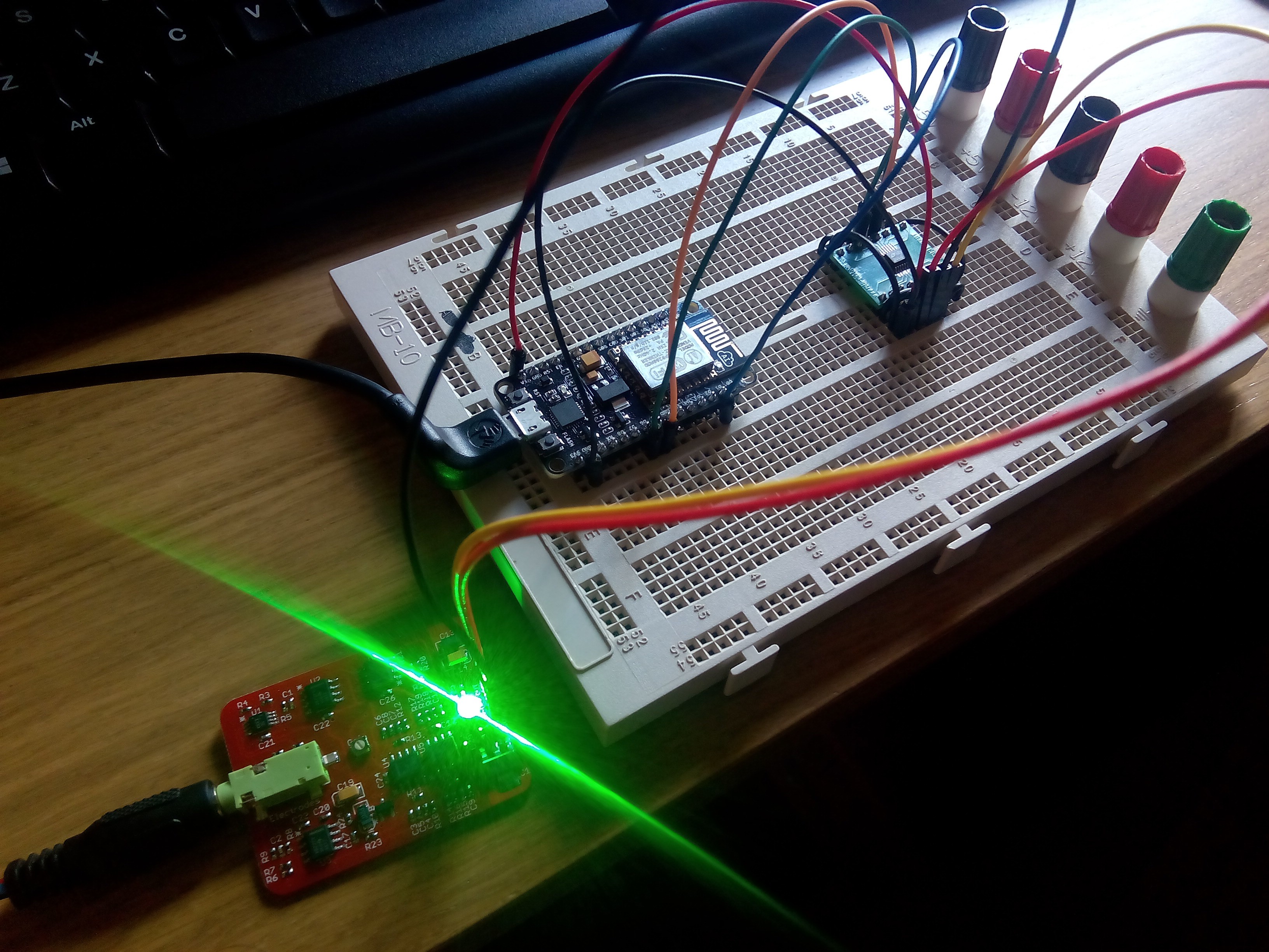
05/17/2016 at 11:15 • 0 commentsWhen I started testing the EMG circuit of Mumai, I used a regular Arduino to digitize the analog signal that the circuit outputs. The Arduino ADC has a 10 bit resolution and a default input range of 5 V (if not using an external analog reference). That is enough since the maximum output range of the EMG circuit goes from 0 to 5 V, with the signal centered at 2.5 V.
However, when I began the integration of the EMG circuit with the ESP8266 to start working on the Mumai nodes, I stumbled upon one little problem: the maximum amplitude that the ESP8266 ADC can measure is only 1 V and there is no external analog reference to have a greater measurement range. So, with a signal centered at 2.5 V, this limited input range meant that EMG data would be completely unusable.
Fortunately, I had one external ADC from some other project lying around: a LTC2440, with an amazing 24 bit resolution, external analog reference and SPI communication. With just the power connections, three wires for the SPI an a small piece of code to retrieve the data from the bus, the first prototype of a Mumai node was up and running.
![]()
-
We have EMG (on the curse of electronics)
03/21/2016 at 19:02 • 0 commentsEveryone who has ever designed an electronic circuit knows the anxiety of the first power up of a new prototype. Maybe it's just me, but rarely a newly designed circuit works as expected the first time electrons start flowing through resistors, capacitors and ICs. Thankfully, we have breadboards and perfboards to build and test a prototype before jumping to a PCB design. But even so, after spending hours soldering your new and shiny PCB, having inhaled the fumes of solder, with back pain and eyestrain, because of some kind of mysterious black magic, you power up the circuit, measure its output and... nothing happens. So it begins the process of "debugging" the circuit: checking and rechecking the schematics and PCB design, testing continuity, measuring the output of every stage... If you are lucky, the problem is due to a faulty IC, or for placing the wrong component. But sometimes the problem is worse, and you have made a design mistake in the connection of some components, or the traces are not wide enough to withstand the current flowing through them, or the grounding is badly designed and induces lots of noise on the system, or you forgot to put that 10 pF capacitor in pin 13 of U4 that didn't seem that important...
Of course, the first test of the EMG sensor was no exempt of the "no signal at the output" problem. Thankfully, the problem was solvable, two components were misplaced and the values of two resistors were wrong. So after desoldering and resoldering the problematic components, I powered the circuit again, measured the output and... hurray!!! A nice and clean EMG signal popped out on the oscilloscope screen. The project goes on.