 Valent Turkovic
-
1Step 1
Firmware configuration and flashing
- Go to Nodewatcher in your web browser
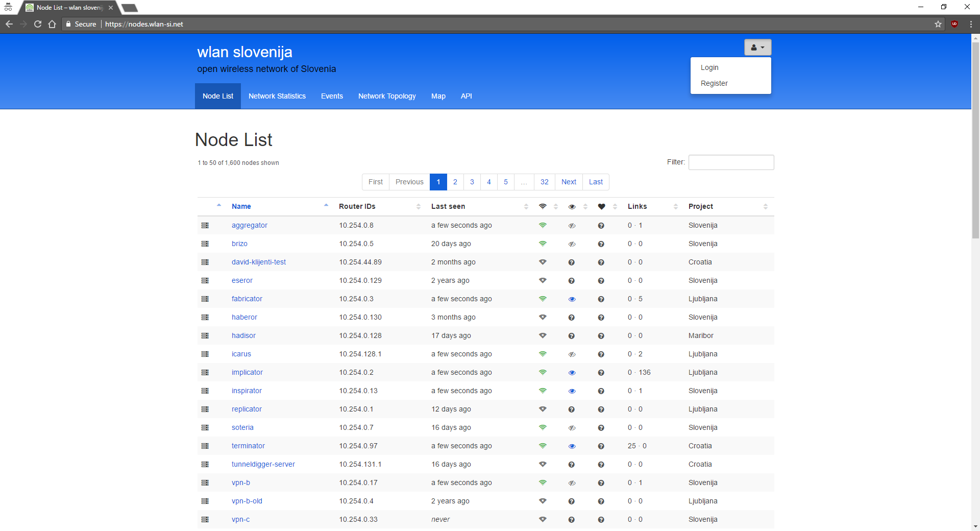
- You need to login or register
Got to right top corner as shown in picture![]() Fill in required information and under Default project select Croatia.
Fill in required information and under Default project select Croatia.
Click on register - You now need to configure firmware for first of three TP Link CPE210 AP-s.
Got to right top corner as shown in picture and click on Register New Node.![]() Now you will see form like one shown in the picture.
Now you will see form like one shown in the picture.![]() Now you need to at least fill out name and select TP Link - CPE 210 as Router from dropdown menu as shown in picture above.
Now you need to at least fill out name and select TP Link - CPE 210 as Router from dropdown menu as shown in picture above.
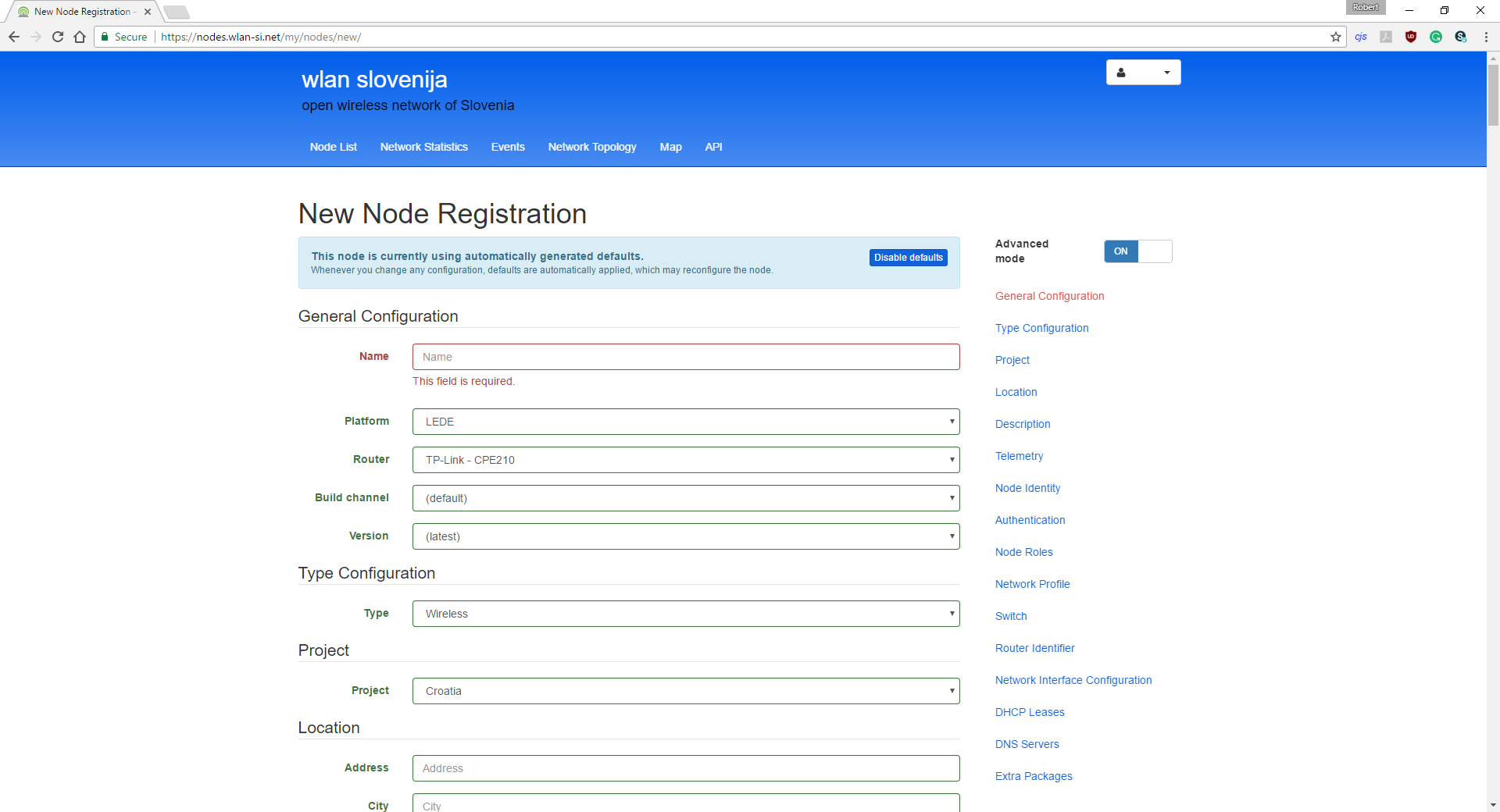
After filling in at least Name and selecting TP Link - CPE 210 as router click on Advanced mode.![]() Now scroll down to the part where you will see Wireless Radio.
Now scroll down to the part where you will see Wireless Radio.![]() Now instead of default channel 8 select channel 1 from dropdown menu.
Now instead of default channel 8 select channel 1 from dropdown menu.
Click on Register at bottom and configuration for first CPE 210 is done.
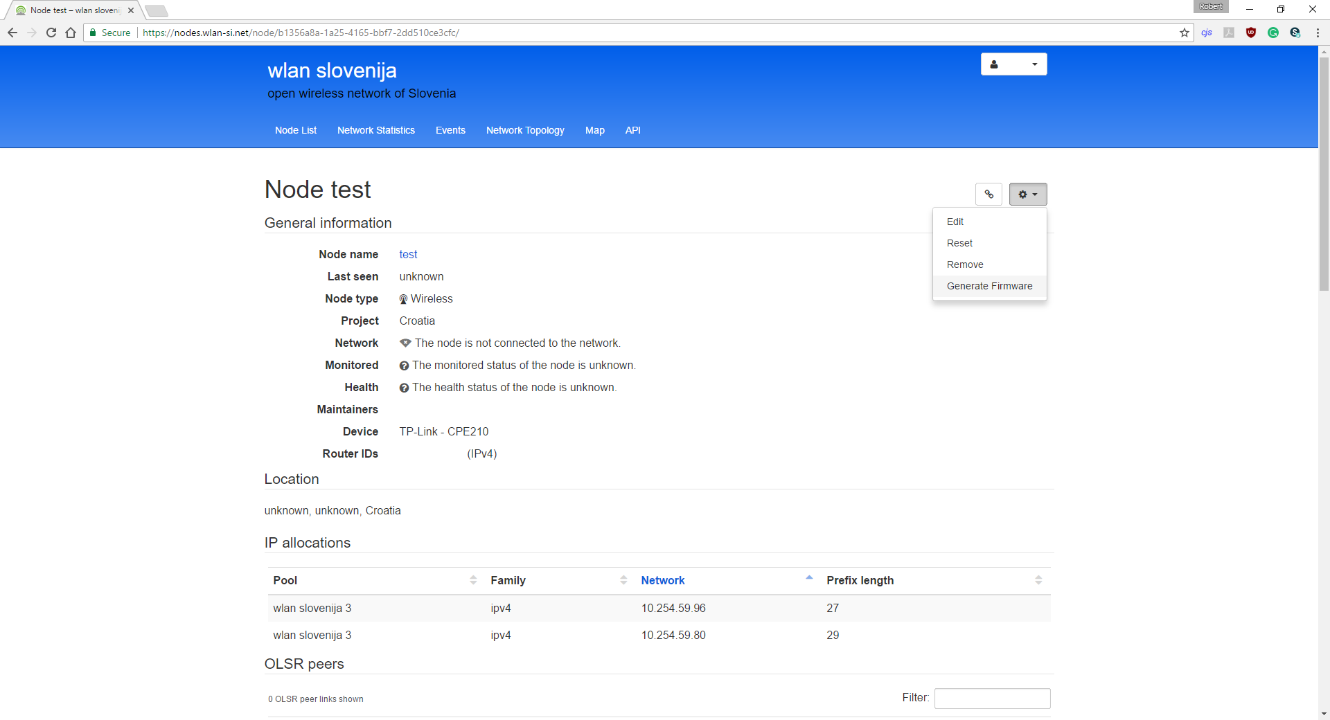
After registration you will be redirected to page containing information about your node.
Now you need to click on Settings icon located on right side.
Now click on Generate firmware as shown in picture.![]()
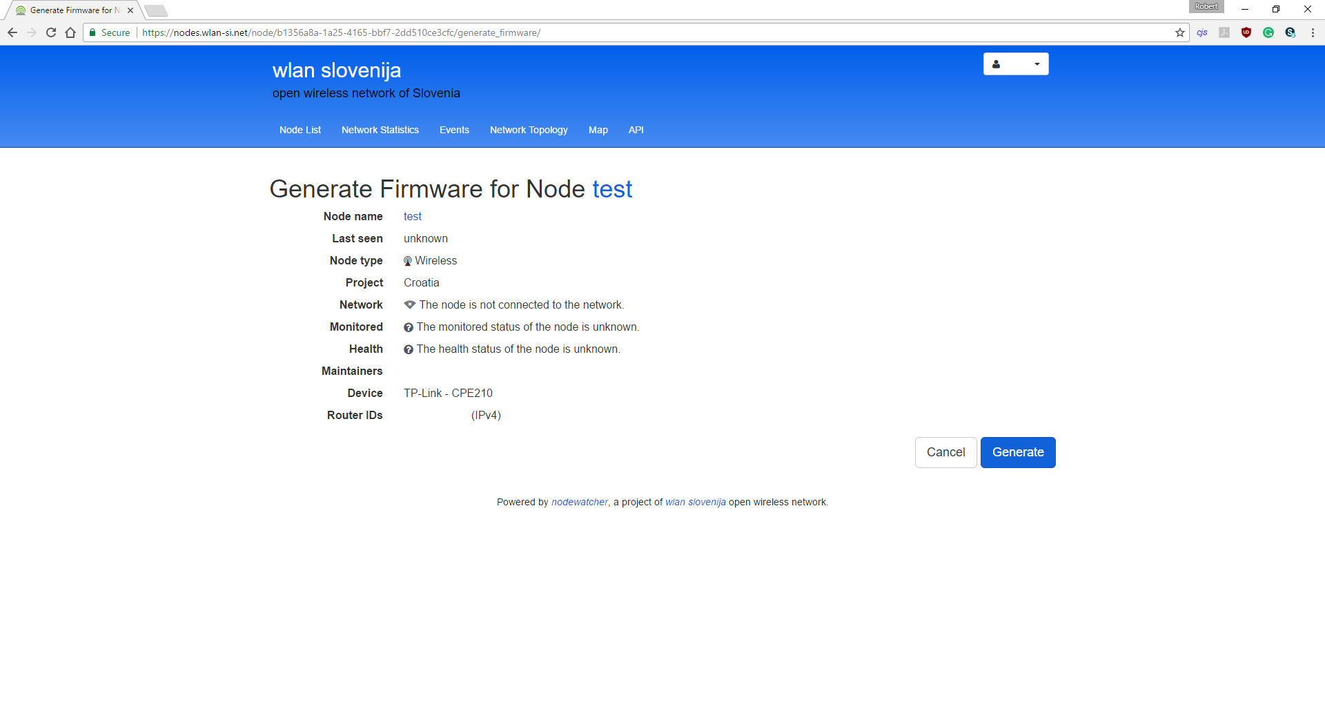
Then you will be redirected to a page to confirm that you want to Generate firmware.
Just click on Generate.![]()
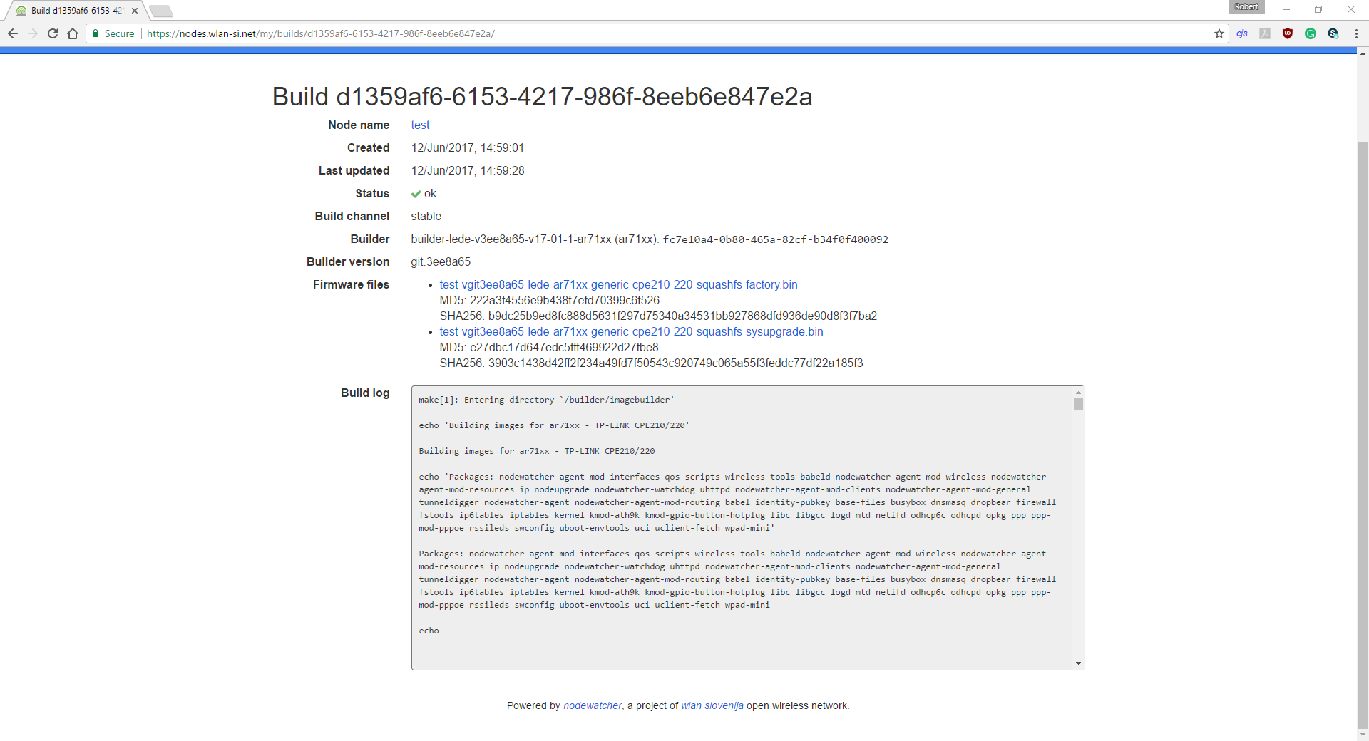
After that firmware will be generated in couple of minutes.![]()
You can wait for it to complete and refresh the page in couple of minutes or continue to next step and configure firmware for second CPE 210. - Second CPE 210 configuration is pretty much the same as first one.
So follow step 3 instructions but with this slight change.
This time select channel 6 instead of channel 1 from dropdown menu. - Third CPE 210 is configured like first two but this time select channel 11 from dropdown menu.
- Now go to the same menu as when Registering a new node but select My Firmware Builds instead.
Then you will se the list of all firmwares built for all of your nodes.
Since this is the first time that firmware is generated for three of your nodes you should see three builds.
Click on first build ID.![]() Then download factory image by clicking on it.
Then download factory image by clicking on it.
Repeat that also for two
-
2Step 2
Device assembly
Prerequisites:
- Make sure you have flashed and configured the firmware of the routers you will be using
- Make sure you have assembled the 3D printed shell
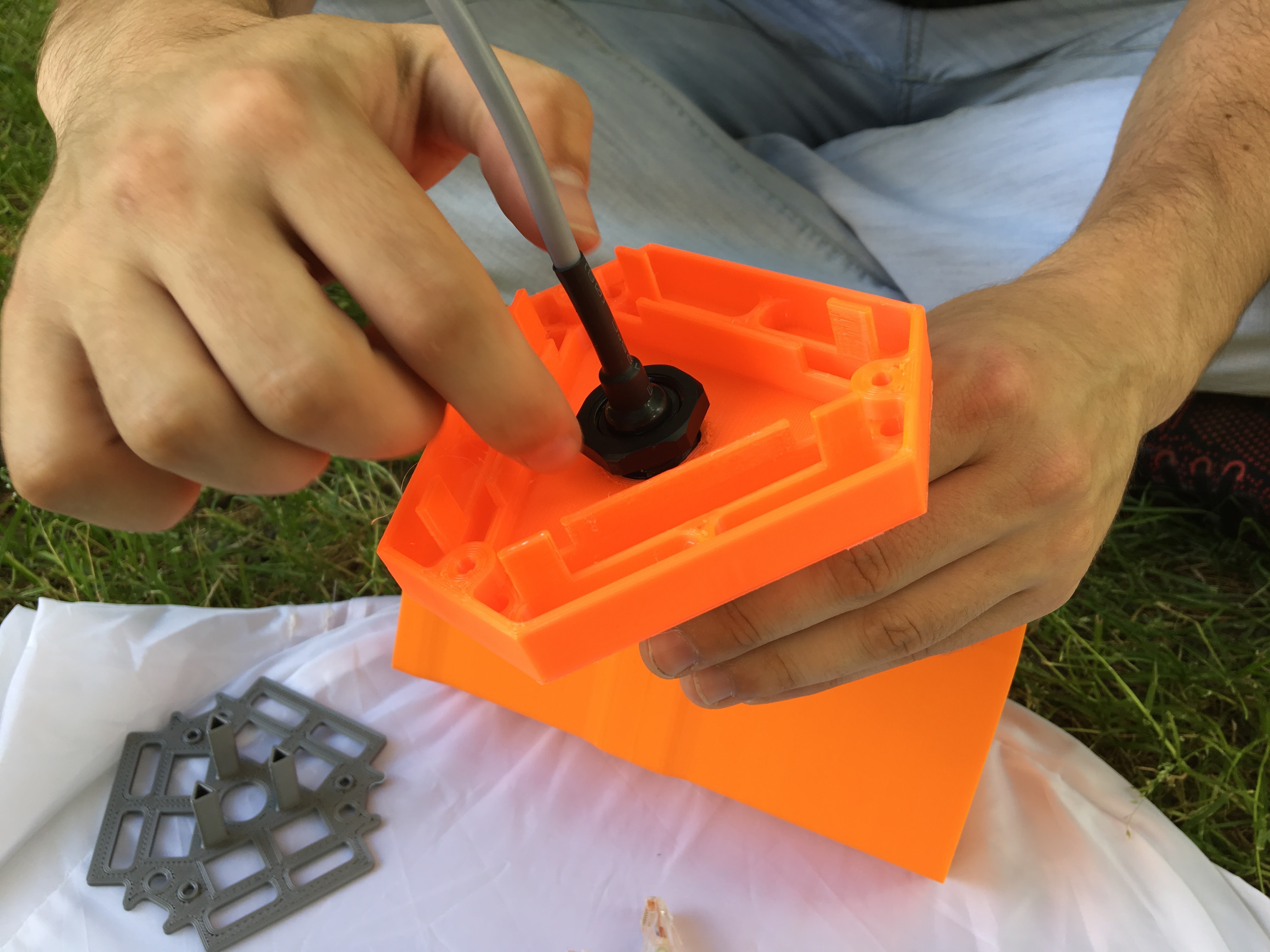
- Mount the outdoor RJ45 connector to the bottom piece. This step does not require any tools. Simply place the connector trough the hole and tighten it using the included plastic nut.
![]()
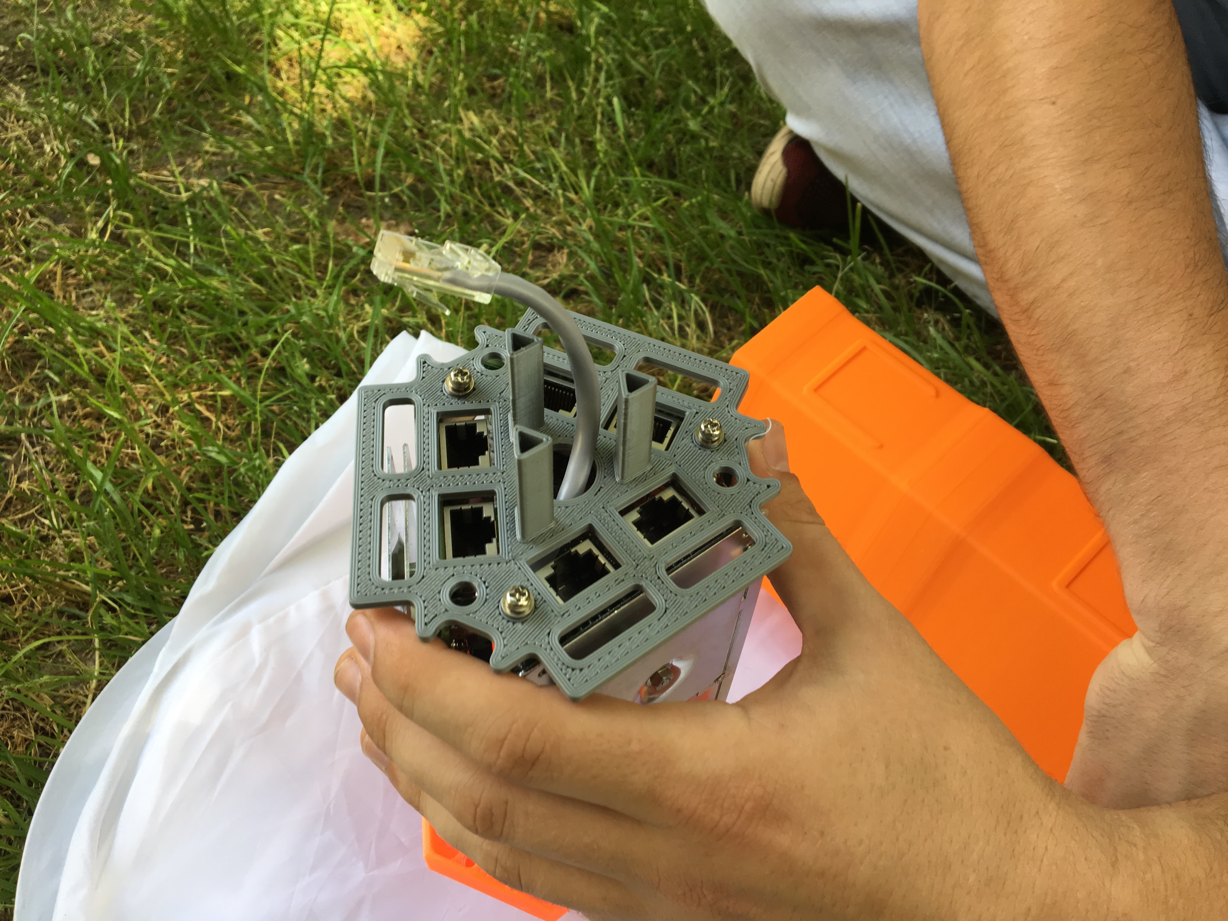
- Place the routers onto the bottom piece with the antennas facing outwards. Cable that goes from the connector should go upwards trough the space in the center.
![]()
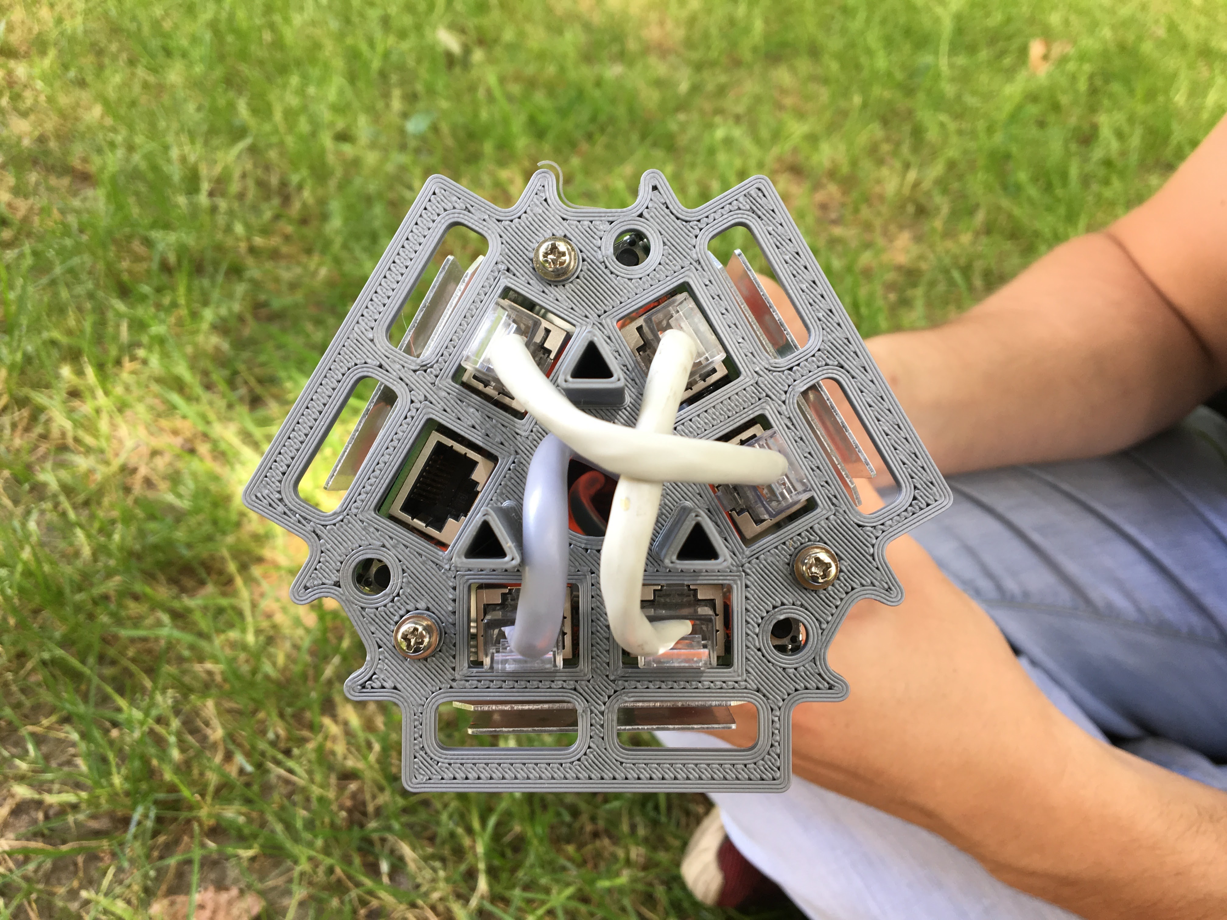
- Place the top part onto the routers. Thread the cable going from the connector trough the hole in the center and secure each router using a screw from the top.
![]()
- Plug the cable going from the connector into the ETH0 port of the first router. Then, using the 10cm patch cable, connect the remaining free port to the ETH0 port of the second router. Then connect the remaining free port to the ETH0 port of the third router using the second patch cable.
![]()
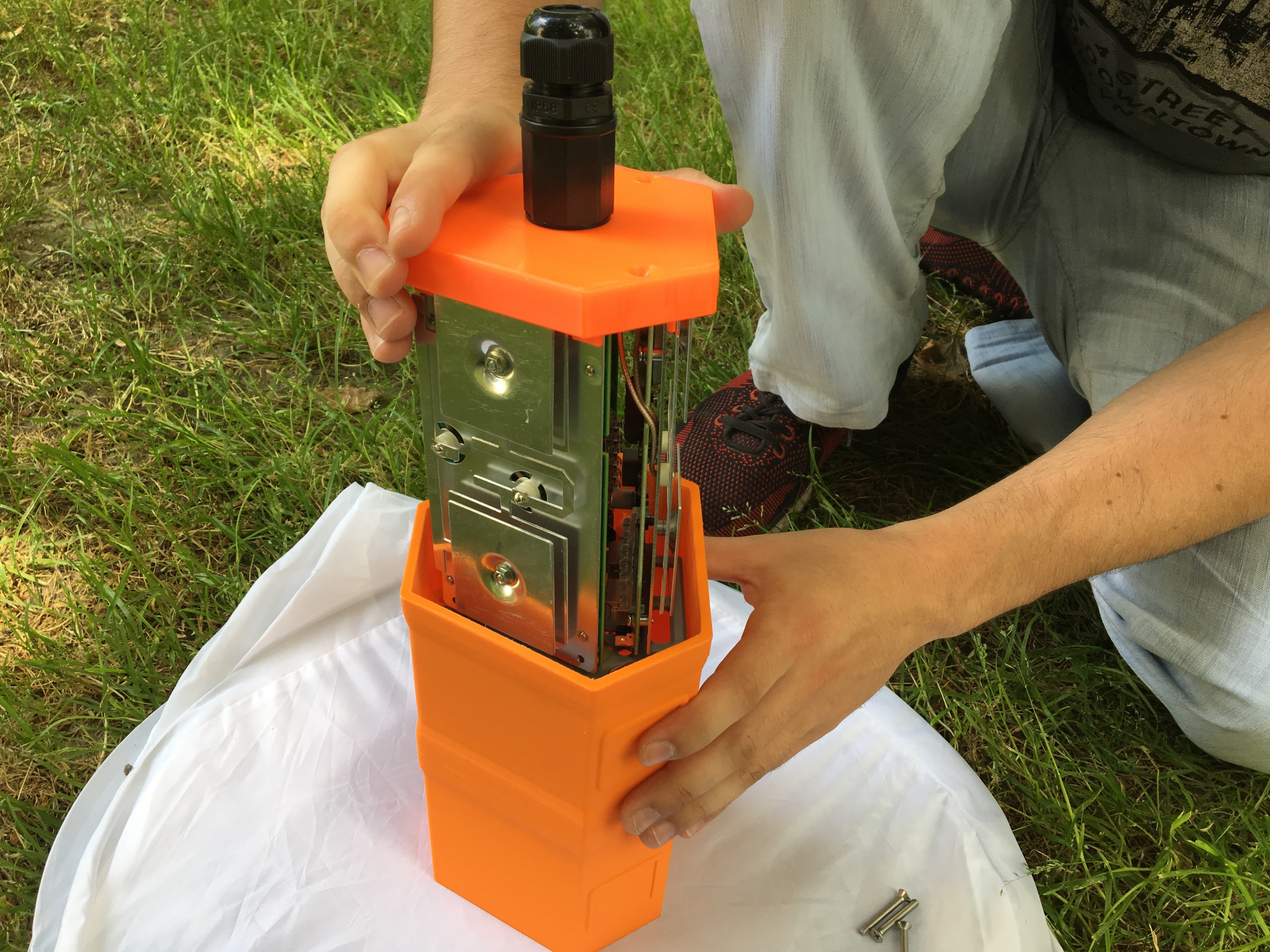
- Carefully place the router assembly inside the shell.
![]()
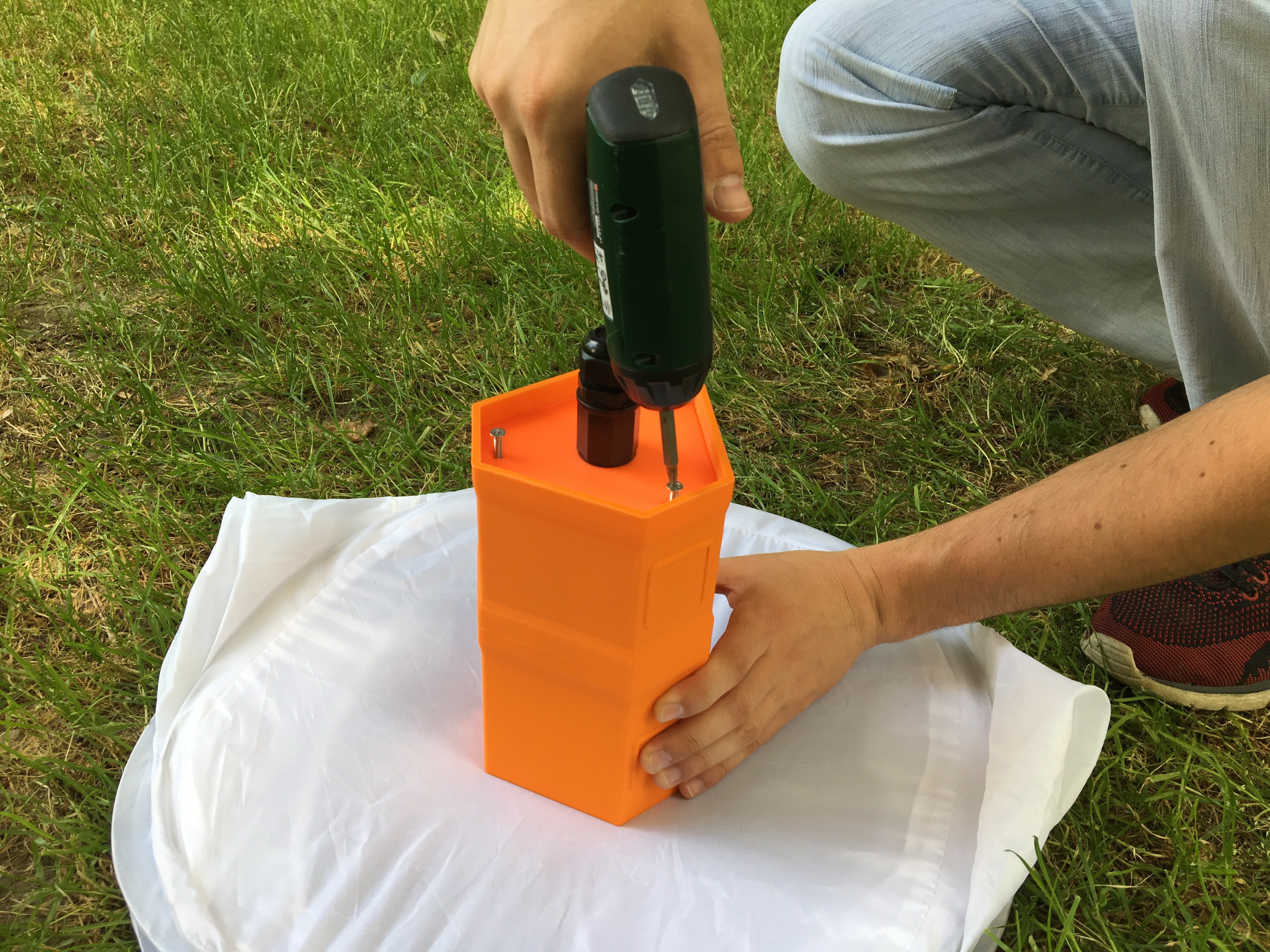
- Secure everything using the M4 screws
![]()
-
3Step 3Final firmware configuration after assembly
In order to use only one UTP cable for data and power to all three CPE 210 AP-s additional configuration is needed.
It is not time consuming and mostly consists of copy/paste.For this configuration you need to be connected to SSID broadcasted by CPE 210.
By default it is otvorenamreza.org- Login to first CPE 210 via SSH
IP can be found on your node details and password by clicking on Settings menu and then on Edit.
It is under authentication section.
Username is root
After logging in you will see basic information about your node.
In order to enable POE to power second CPE210 you need to issue following commands.echo 20 > /sys/class/gpio/export echo out > /sys/class/gpio/gpio20/direction echo 1 > /sys/class/gpio/gpio20/value
- After that second CPE210 will power on.
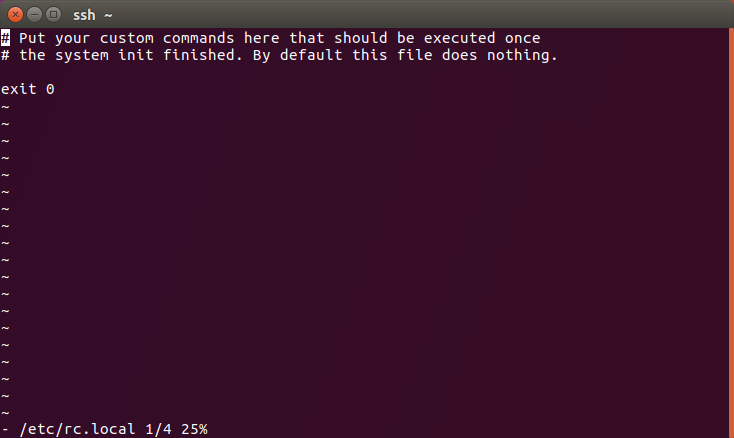
Then in order to enable POE to second CPE 210 after the devices have been rebooted you need to edit rc.local file.
Issue the following command:vi /etc/rc.localThen you should see the following.![]() In order to edit the file in vi text editor you need to simultaneously press SHIFT+I keys.
In order to edit the file in vi text editor you need to simultaneously press SHIFT+I keys.
That way you enter Insert mode.
After that copy and paste commands from step 1.
Contents need to be after line 2 and before line containing exit 0.
File should look like this:![]()
If it looks like that press ESCAPE key and then type :wq
That will save and exit.
You have completed configuring first CPE 210. - In order to configure second CPE 210 follow same instructions like for first one but with IP and password of the second one.
- Third CPE 210 does not need additional configuring.
You are done with assembly and configuration of your Meshpoint.
- Login to first CPE 210 via SSH
MeshPoint - wifi router for humanitarian crisis
Autonomous, smart, wifi mesh router which is easy to use by humanitarian NGO first responders during humanitarian or natural disasters.
 Fill in required information and under Default project
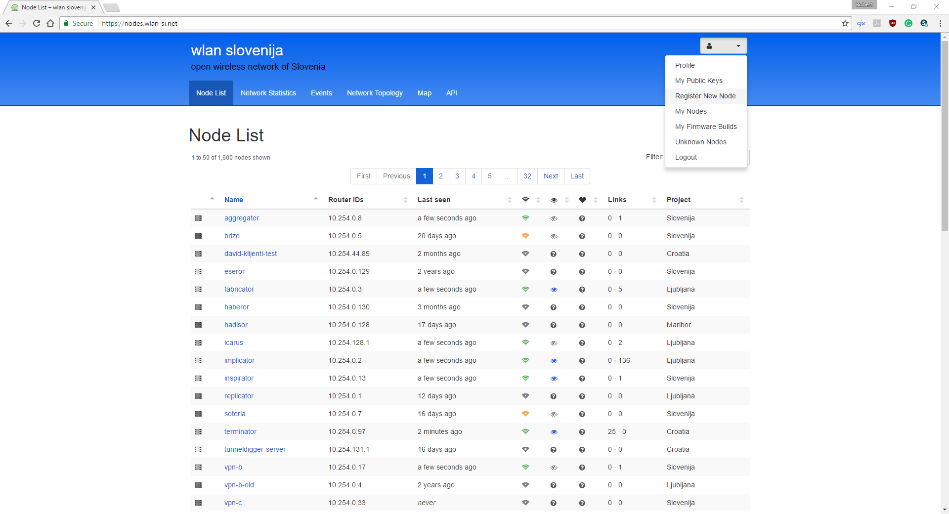 Now you will see form like one shown in the picture.
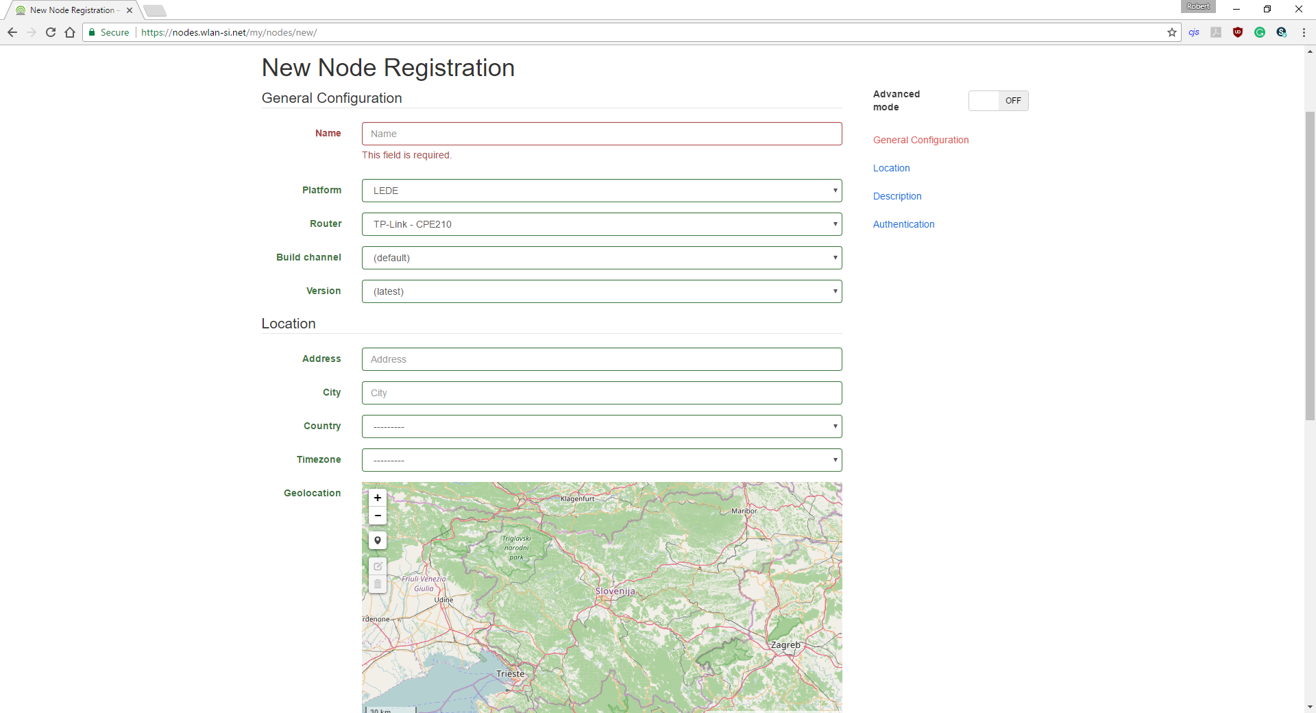
 Now scroll down to the part where you will see Wireless Radio.
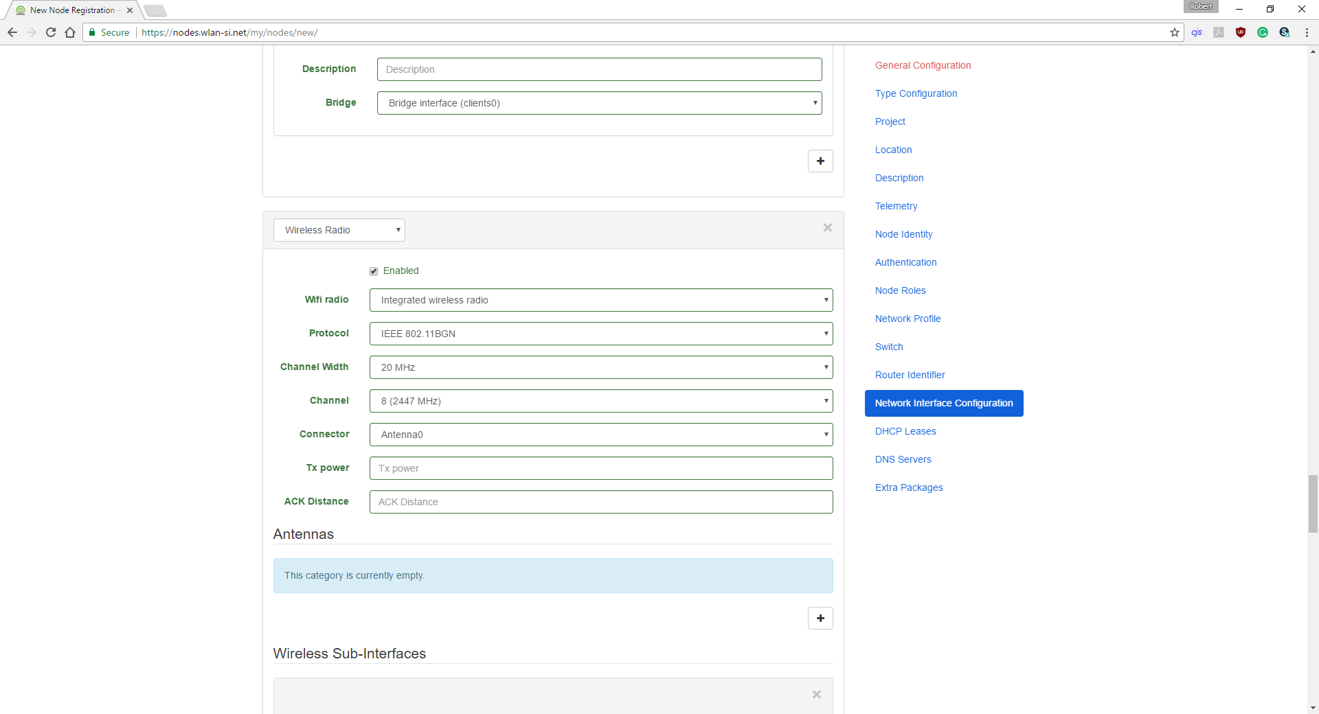


 In order to edit the file in vi text editor you need to simultaneously press SHIFT+I keys.
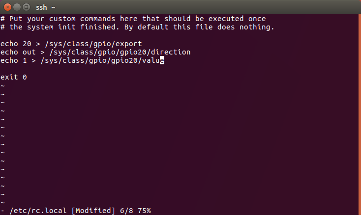
Discussions
Become a Hackaday.io Member
Create an account to leave a comment. Already have an account? Log In.