Close
0%
0%

SunLeaf

A solar powered wireless picopower sensor module with cloud Datalogging and control geared towards agriculture and environmental monitoring

avrAVR
Similar projects worth following
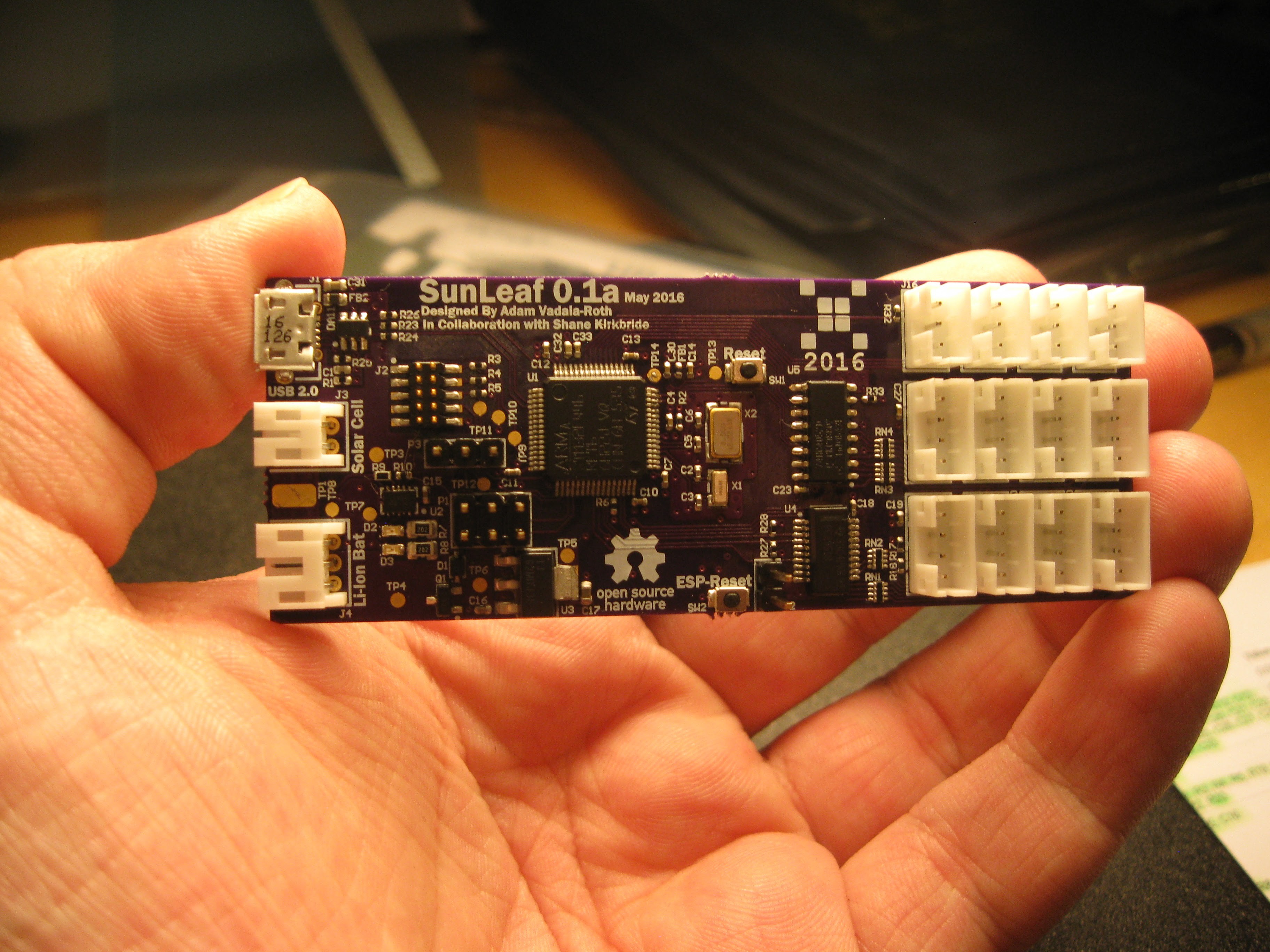
The SunLeaf is a wireless sensor module for remote sensing applications. SunLeaf will be geared towards plant health and environmental sensing in the areas of climate, agriculture, air quality, and water quality. The module also aims to be cheap for widespread adoption and scaling up deployment. SunLeaf also uses Seeedstudio grove connectors giving it a wide range of existing sensor hardware to utilize cheaply. The module connects to a PC over USB to be configured or the kindsof sensors it has and its given application. The data sampled by the module is sent to an MS Azure cloud storage system where the data can be viewed in a web interface behind a user login.

Module Hardware Specs
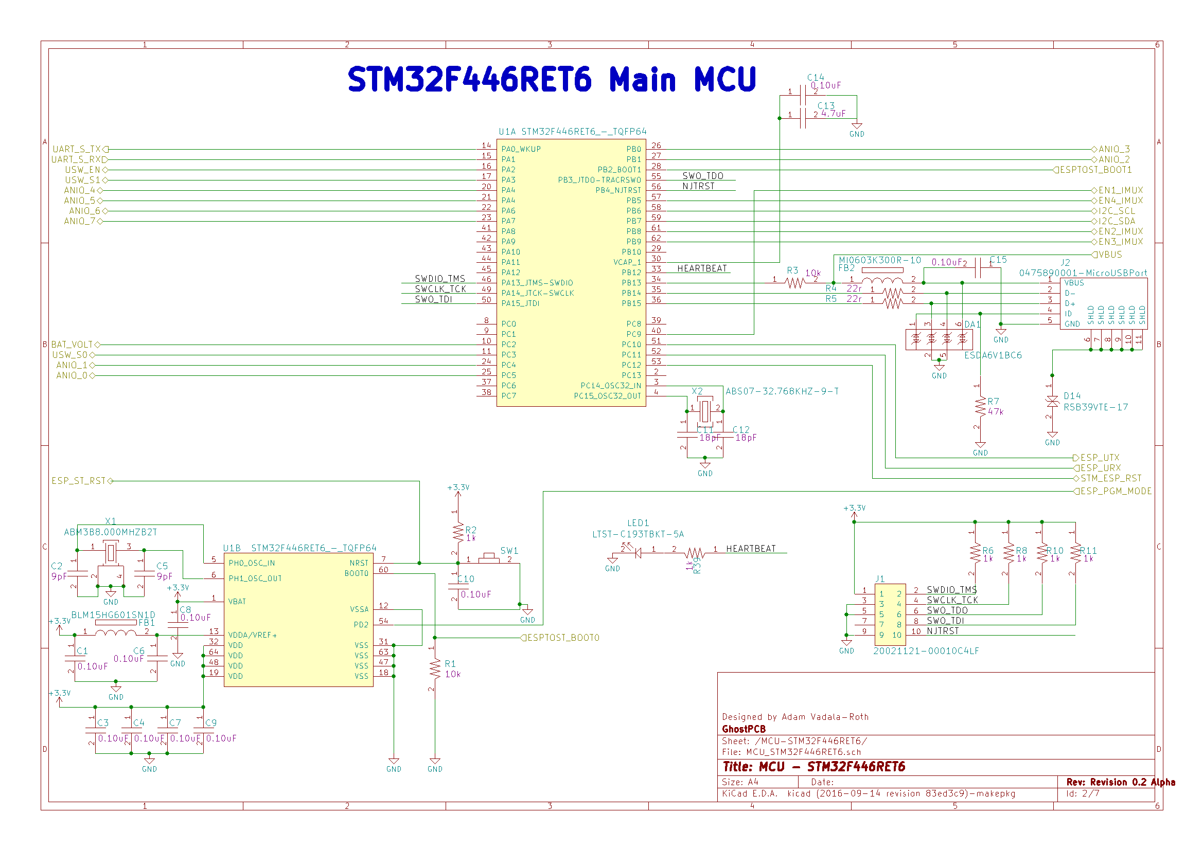
- ST Microelectronics STM32F446RET6 ARM Cortex M4F 168MHZ MCU
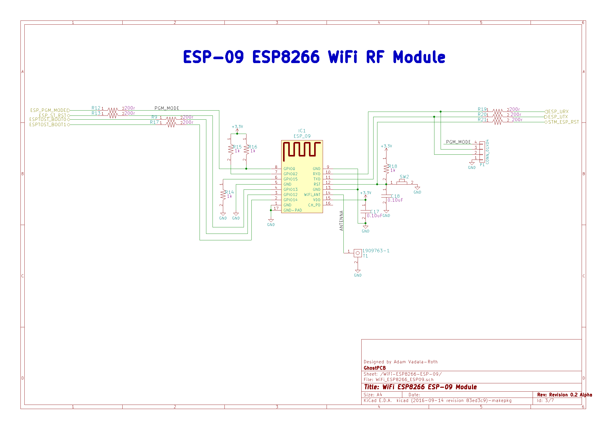
- ESP-02 ESP8266 WiFi Module
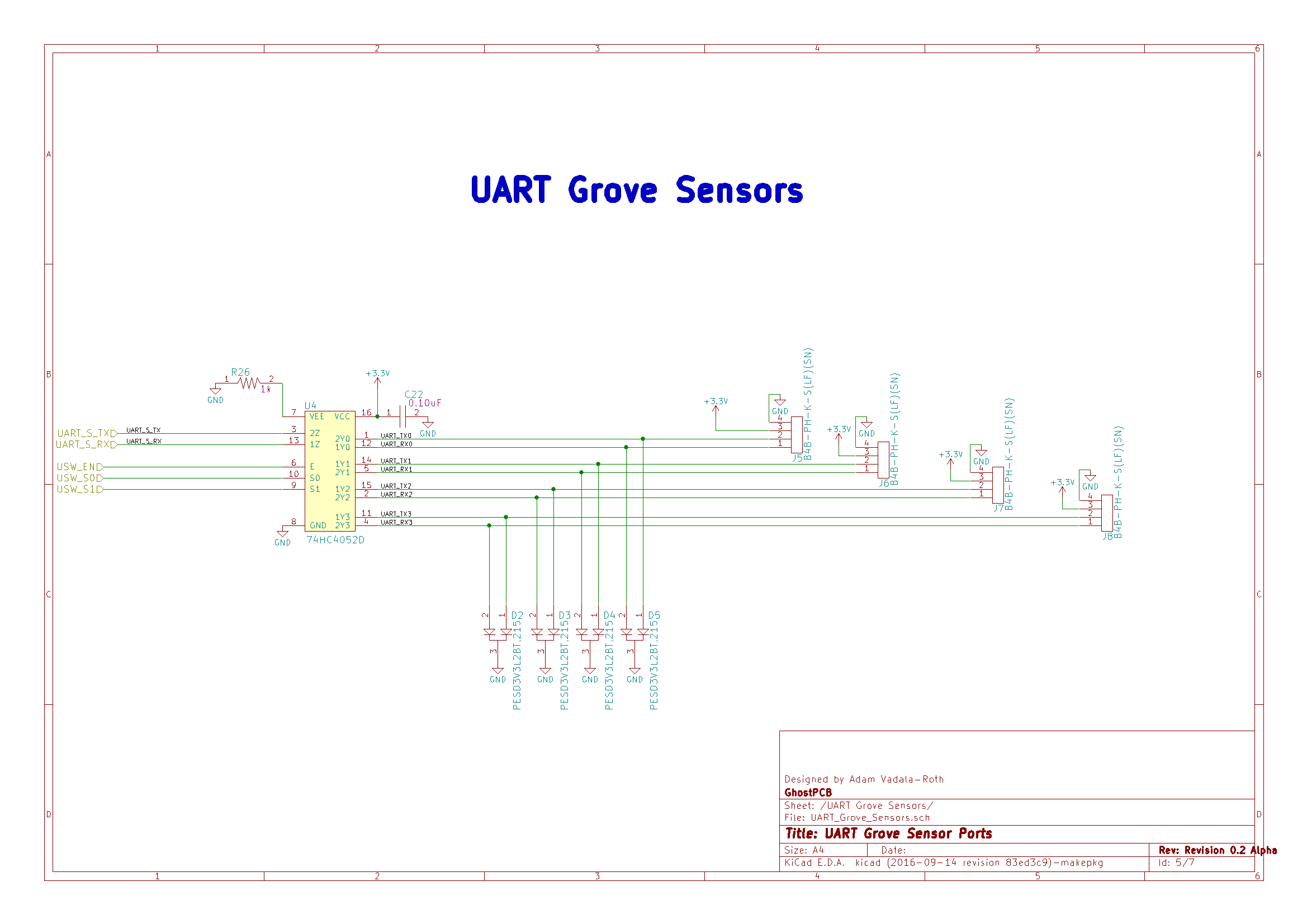
- 4x Seeedstudio UART/USART Grove Sensor Connectors
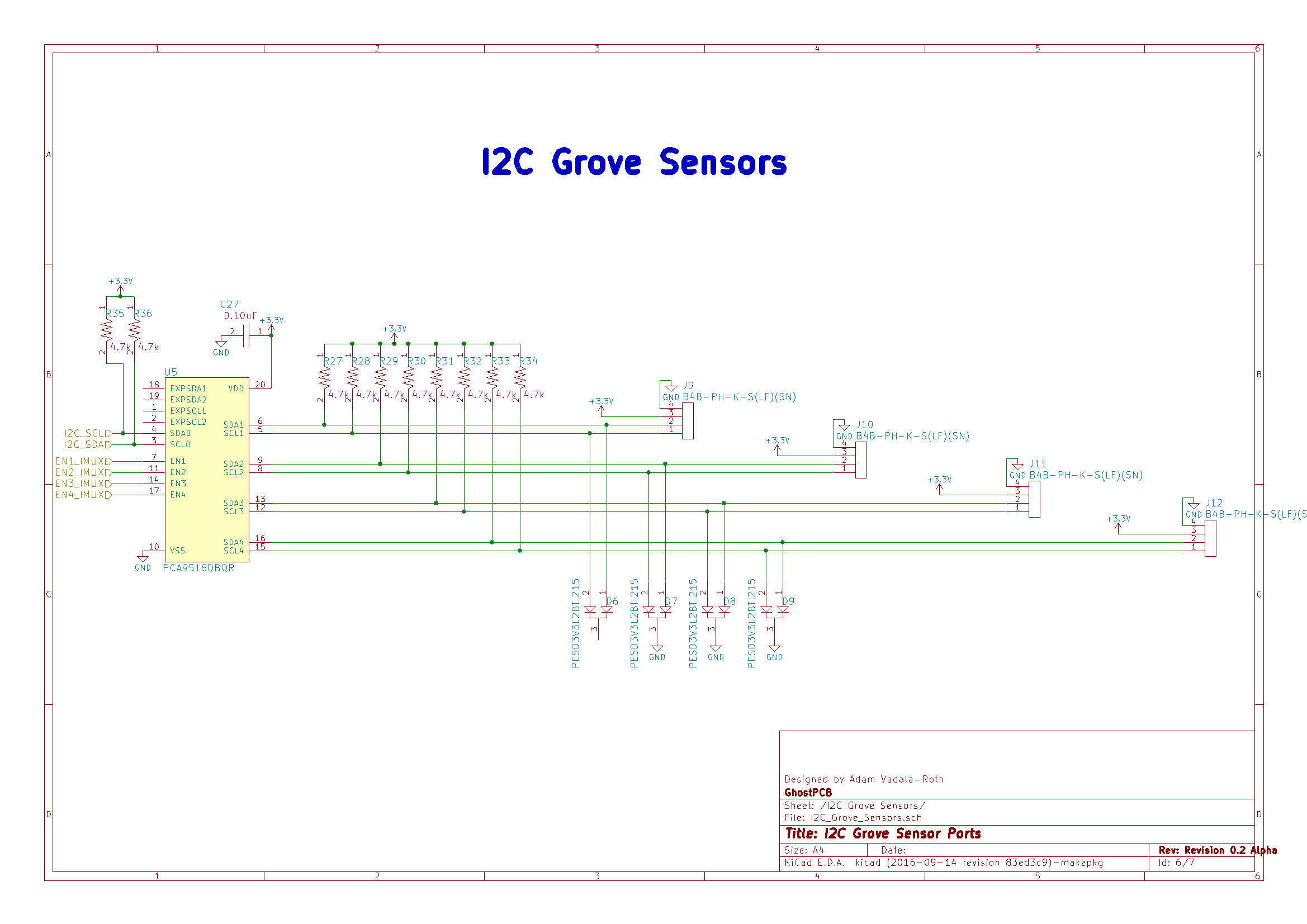
- 4x Seeedstudio I2C Grove Sensor Connectors
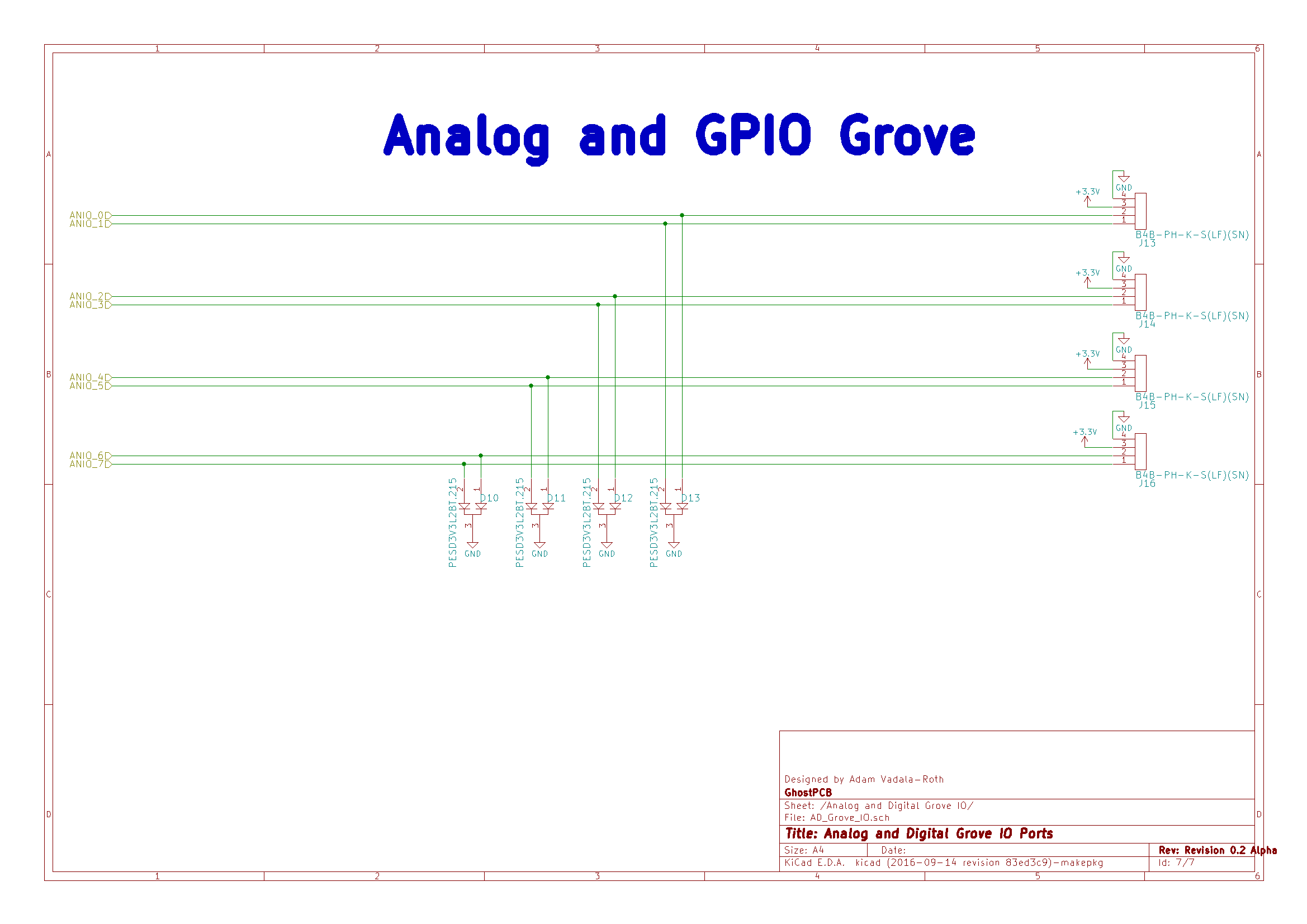
- 4x Analog Sensor Inputs (3 Pin Grove)
- USB 2.0 Connectivity for Development and Battery Charging
- Solar

SunLeaf

An Open Source Sensing Module
Abstract

The SunLeaf is a wireless sensor module for remote sensing applications. The module is solar/battery powered, low power, connected via WiFi, low cost, and highly scalable. SunLeaf interfaces with several variety sensors, samples, and transmits the data to the cloud. Data is viewed through a web interface. The SunLeaf module intends to be a solution for many remote wireless sensing applications, such as plant health, agriculture, monitoring pollution, and monitoring climate.

Overview

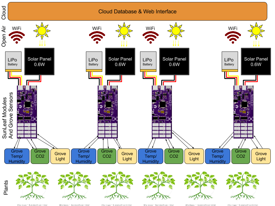
SunLeaf is a wireless sensor module for remote sensing applications. The module is a simple low power device that interfaces with sensors and transmits that data to the cloud. The SunLeaf hardware makes up a rather complex printed circuit board. The brains of the device are an ARM Cortex M4 microcontroller and an ESP8266 module. The ARM interfaces with the sensors, and is the general brains of the device, the ESP8266 acts as a dedicated WiFi modem and interface to the web. SunLeaf will be able to perform firmware updates over the air. Sensors connect to the module via SeeedStudio Grove sensor connectors, SunLeaf accepts up to four UART, I2C, and analog/GPIO variety sensors. Module power is supplied by an onboard lithium ion battery, of which is charged by an onboard charge controller via solar panel or USB. Configuring the module for a given sensing application is performed by connecting with a PC either over USB or WiFi. The data logged from the sensors attached to a SunLeaf module is logged into https://thingspeak.com/ channel.
Inspiration, and Why

SunLeaf has roots dating back to HydroPWNics in spring 2015. Originally SunLeaf was going to be a redesign of the sensor modules and module hub as a standalone board. A module for interfacing with both digital sensors and analog sensors transmitting it over WiFi. Just being able to interface sensors and transmit data wirelessly wasn't enough, so the ability to run off a solar charged battery was added as a core feature. Solar power is an important feature because the module will be self sustaining also it makes the project innovative being one of the first solar powered sensor modules of this kind. All those features packed together made the module capable of much more than monitoring plant health and the environment. In short SunLeaf is a solar/battery powered pic power wireless sensing module for all wireless sensing applications.

Applications

Hydroponics:

SunLeaf has its roots in hydroponics, given that it is an evolution of the original hydroPWNics project’s electronics. In the application of hydroponics SunLeaf would be employed for monitoring the environment of the plant grow room. Multiple SunLeaf modules would be deployed along with a multitude of SeeedStudio Grove temperature and humidity modules. Additionally a single SunLeaf with equipped with Atlas Scientific (https://www.atlas-scientific.com/ ) pH, dissolved oxygen, electrical conductivity, temperature, and ORP sesnsors, these sensors will allow precise monitoring of water quality and with software monitoring of the nutrient content of the water. The same SunLeaf in charge of water quality monitoring would also be setup with additional hardware for controlling pH and delivering nutrients to the water supply. All SunLeaf units in the grow room should be able to run off excess light from the grow light units.

Water Quality Monitoring:

As mentioned in the hydroponics application SunLeaf also has use in water quality monitoring and management. The application is not limited to hydroponic water monitoring. Another application is pool water quality monitoring, make sure there isn’t too much or too little chlorine in the pool. A SunLeaf would be setup in a waterproof enclosure with the right probes with the solar panel on top, it would just float in the pool and run of the sun. In some parts of the country some folks do have access to water utilities provided by their town, in this case they have a water well that...

Read more »

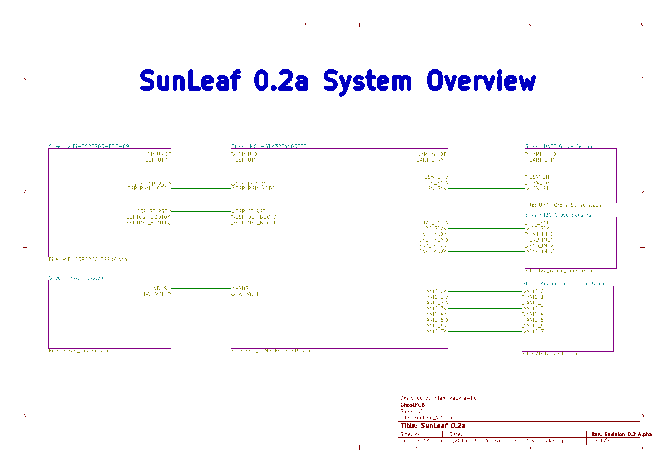
SunLeaf - Big Picture - White Background.png

PNG Graphic of complete System overview.

Portable Network Graphics (PNG) - 224.39 kB - 10/09/2016 at 23:37

Preview

SunLeaf.pdf

PDF of SunLeaf 0.1a Schematic this is the original version of the SunLeaf PCB hardware.

Adobe Portable Document Format - 3.84 MB - 10/09/2016 at 22:27

Preview

SunLeafV2.pdf

PDF of the SunLeaf 0.2a schematic. This is the new version of SunLeaf pending fabrication and testing.

Adobe Portable Document Format - 153.44 kB - 10/09/2016 at 22:26

Preview

APACHE_LICENSE-2.0.txt

Apache License 2.0 this license is for mBed and the firmware residing on the STM32 which is based on mBed' ARM GNU Toolchain export.

plain - 11.09 kB - 10/09/2016 at 22:24

Download

ESP-Link-License.txt

License for ESP-Link software, which our ESP8266 firmware is a fork of.

plain - 5.35 kB - 10/09/2016 at 22:23

Download

View all 18 files

  • 1 × STM32F446RET6 ARM Cortex M4F 168MHZ MCU
  • 1 × ESP-09 Batteries and Battery Accessories / Battery Chargers
  • 1 × 500mA LiPo Battery
  • 1 × 2.5W Solar Voltaic Cell
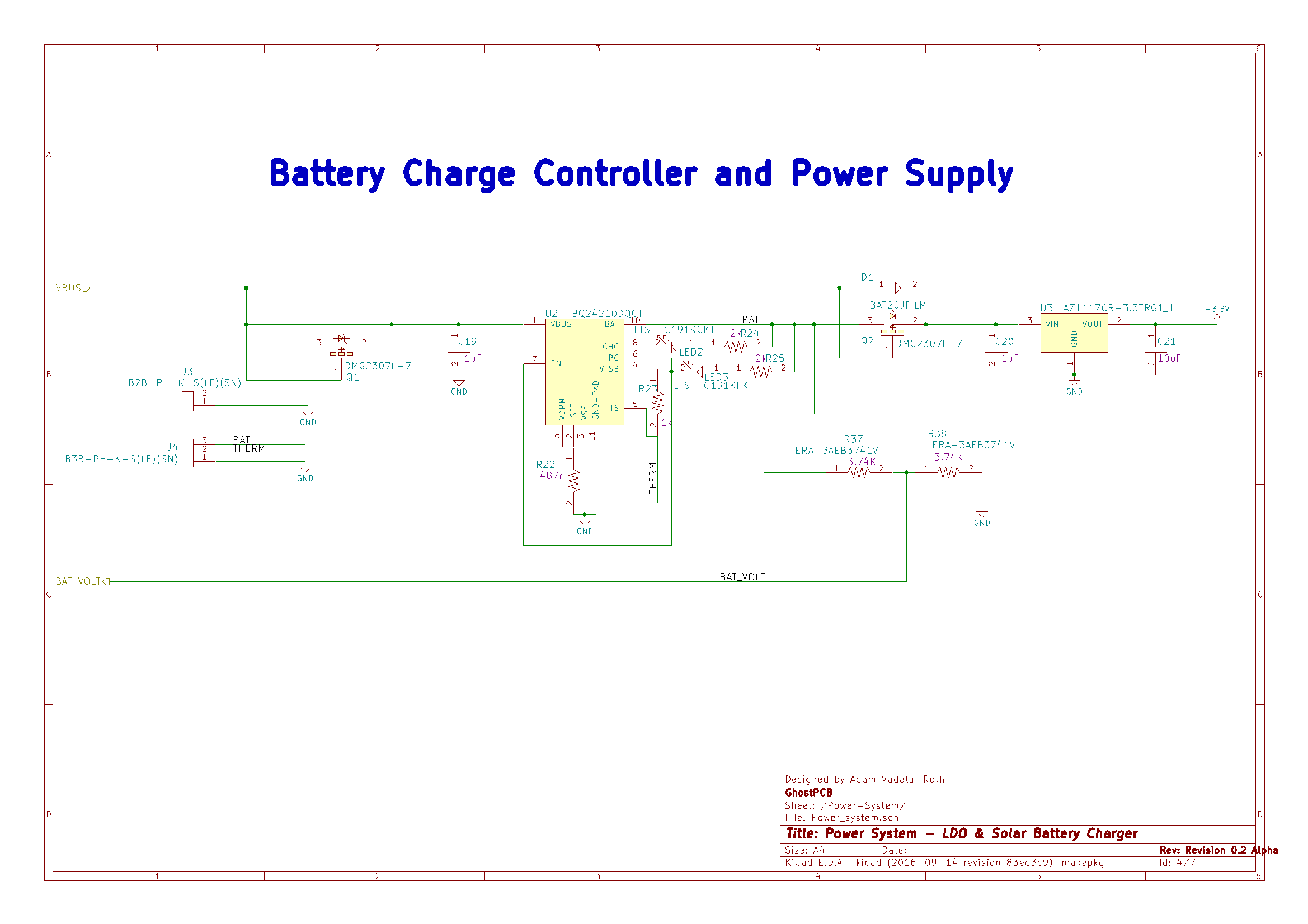
  • 1 × BQ240210 Solar or VBUS Powered LiPo battery charging IC

View all 6 components

  • SunLeaf as a Product or Commercial Solution

    AVR11/29/2020 at 01:43 0 comments

    Hope everyone's holiday season is off to a good start despite the pandemic still in full swing. As some of you may know SunLeaf has been continued as part of a bigger project on here called Agricoltura IO. 

    At this time I am working on the project again and focusing on making it more appealing as a product or commercial application. I would like to hear from folks that are interested in this and what sort of applications they would want to use SunLeaf for and what sort of feature's they would like to see. Feel free to comment on this project log or message me directly with your thoughts and concerns. Things are about to get more exciting this winter. 

    Thank your for your continued support of all my projects over the years on this platform!

    Happy Hacking!

  • Future: Agricoltura IO

    AVR04/25/2020 at 00:49 0 comments

    Hey folks just an update saying this project is not dead, its in the process of being refreshed as part of my latest agriculture sensing platform Agricoltura IO you can learn more about it here: https://hackaday.io/project/173362-agricoltura-io

    Agricoltura IO Is a agriculture sensing and control platform relying on a RS485 sensing and control nodes that are controlled by a gateway control that links RS485 and wireless networks together pushing their data into a cloud database and browser control panel. SunLeaf has now evolved into a family of 4 wireless devices and will be part of the new Agricoltura IO system. So again please head over to the new page to learn about the new family of hardware and the new Sunleaf modules. This page will be updated further down the line when I start working on the new Sunleaf boards, right now the priority of Agricoltura IO is the RS485 based Vine and Ivy modules. 

    https://hackaday.io/project/173362-agricoltura-io

    Stay tuned for more updates

  • It Ain't Over!

    AVR12/06/2016 at 04:22 1 comment

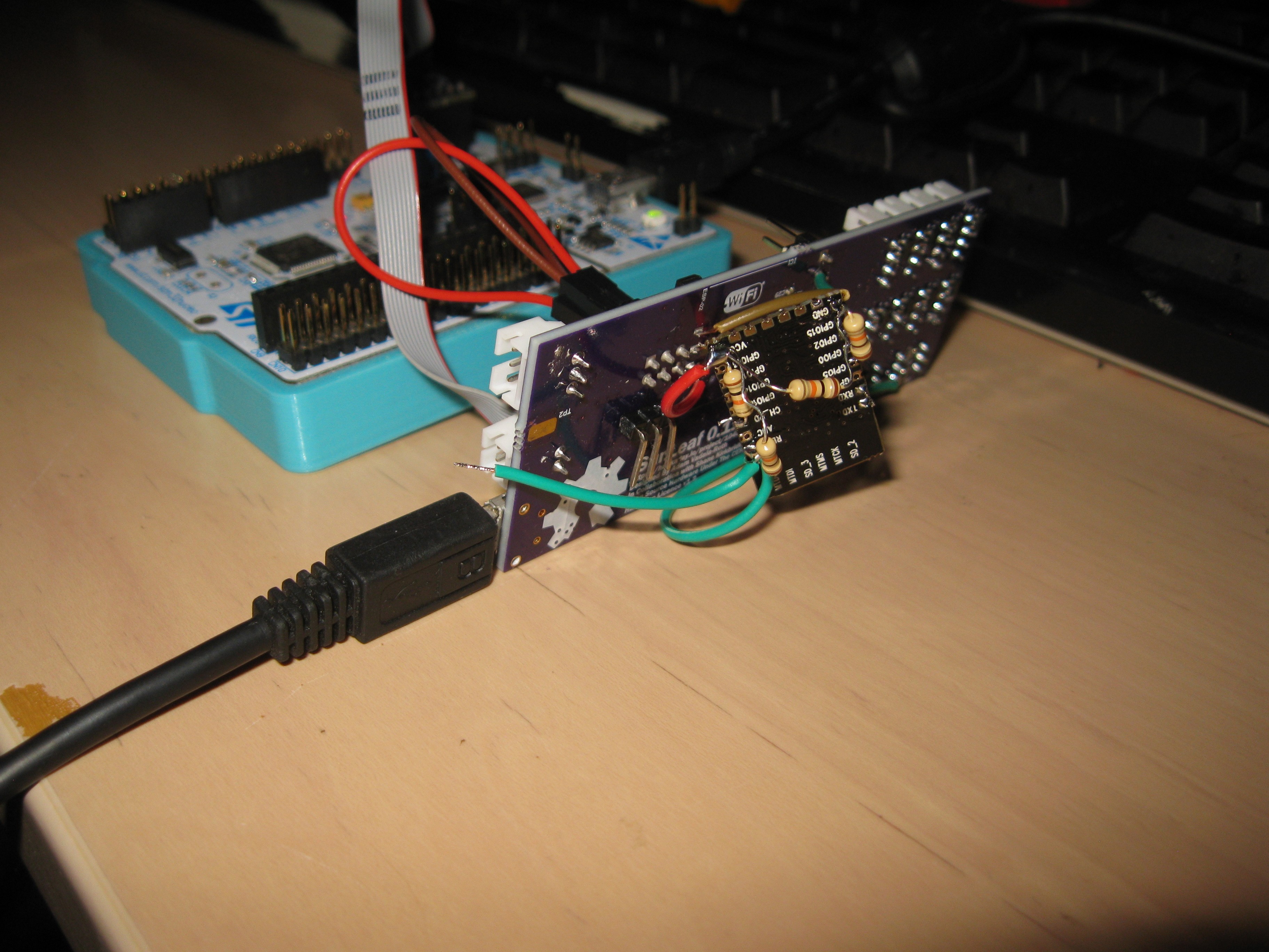
    So the competition is over but that just means we are getting started!! Given that SunLEaf is a continuation and spiritual successor to the electronics and sensing package of last years hydroPWNics it only makes sense to keep going and iterating the system until its solid and flawless. Anyhoo we got the SunLeaf rev 1 PCB posting to thingspeak shortly after the final submissions. This was achieved by grafting an ESP-12E module dedbug style to the pads meant for the ESP-02 module that was originally chosen for the SunLeaf PCB rev 1.

    Not my proudest moment or cleanest assembly/build but the damn thing works! And it even works well off battery power (battery not pictured). What is next is to create a version of the PCB that works flawlessly. I have already teased and shared the nearly solidified SunLeaf V2 design a few times arleady. The reason why it has yet to be fabricated is because the WiFi module needs to be tested separately. On the open web there are not many people using the ESP-09 module, I am using it since its very barebones and allows for a smaller PCB layout allowing my to mount it top side on the rev2. So in order to confirm this module before running another 4 layer PCB through the fab process, I made a small two layer PCB that will allow me to test the ESP-09 module and our software for the ESP8266.
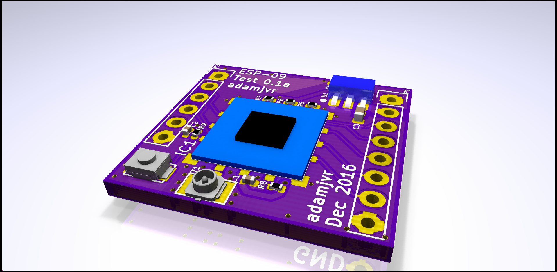
    Here it is :

    https://github.com/adamjvr/ESP-09-Test

    Its on its way to the fab already, when the boards come in should take me a day to complete my evaluations. If everything works the way I hope then SunLeaf rev2 will be a go and be 99% likely to be fully functional! Stay tuned as the open source sensing revolution continues to unfold on Hackaday!!!!!!

  • Finals Video!!

    AVR10/10/2016 at 05:38 0 comments

    So with the Hackaday Prize coming to a close we present our working prototype video

    This our working prototype posting sensor data to thingspeak. The SunLeaf prototype is sampling from DHT and light sensor then posting the data. The end of the competition is not the end for SunLeaf, we will continue to work to get our PCB-prototype to the same level of functionality as our working prototype, stay tuned for more updates to this post and future project logs, we are just getting started ;)

  • Test Points Can't Forget Those

    AVR10/04/2016 at 01:36 0 comments

    So we got another update on the hardware revision today. Two logs back I mentioned that some of the further tweaks to the 0.2a design would be test points. Since the last log I have been working on just that. Test points are very important when designing mixed signal circuit boards with lots of stuff packed on to them. Test points are typically used for debugging problems with the circuit that the designer didn't expect , they are handy for development software debugging, and lastly they are import for confirming desired function of hardware after being assembled in the factory.

    The first version of the Sunleaf version 0.1a had test points but not enough of them, there were a few signals here and there that we wanted to be able to probe more easily. Also version 0.1a did not have nearly all the signals for testing complete function since we are looking at mass production we need to have all the important signals available as test points so we can ship working boards. So here is a quick look of the SunLeaf with the newly added test points:

    You can see that many test points were crammed onto the PCB without altering its size further. This should make testing and development a lot easier, as we move forward. The signals that now have test points indlude:

    - UART_S_TX - UART TX for sensors, runs to the multiplexer/demultiplexer

    - UART_S_RX - UART RX for sensors, runs to the multiplexer/demultiplexer

    - USW_S1 - UART multiplexer toggle

    - USW_EN - UART multiplexer enable

    - USW_S0 - UART multiplexer toggle

    - BAT_VOLT - Battery voltage sense signal. right off the voltage divider

    - I2C_SCL - I2C SCL running from MCU to multiplexer

    - I2C_SDA - I2C SDA running from the MCU to multiplexer

    - EN1_IMUX - I2C multiplexer toggle 1

    - EN3_IMUX - I2C multiplexer toggle 3

    - EN2_IMUX - I2C multiplexer toggle 2

    - EN4_IMUX - I2C multiplexer toggle 4

    - ESPTOST_BOOT1 - ESP to STM32 BOOT1 Pin

    - ESPTOST_BOOT0 - ESP to STM32 BOOT0 pin

    - ESP_ST_RST - ESP to STM32 reset toggle

    - USB: D+, D-, VBUS - USB signals

    - ESP_PGM_MODE - ESP program mode signal coming off the STM32

    - ESP_URX - UART RX running to ESP

    - ESP_UTX - UART TX Running to ESP

    - STM_ESP_RST - STM32 toggle ESP reset

    - Solar input

    - BAT - battery signal

    - THERM - battery thermistor signal

    - Power Good on charge controller

    - Charge good signal on charge controller

    - LDO regulator input and output.

    Now there are not test points on 100% of the pins/signals. The sensor connectors have been left out, only because they will either be met with connectors or pogo pins on the factor test jig PCB. So that concludes our test points. Stay tuned as we get closer to the next build!

  • Fabrication Prep and Bill of Materials!

    AVR10/03/2016 at 22:12 0 comments

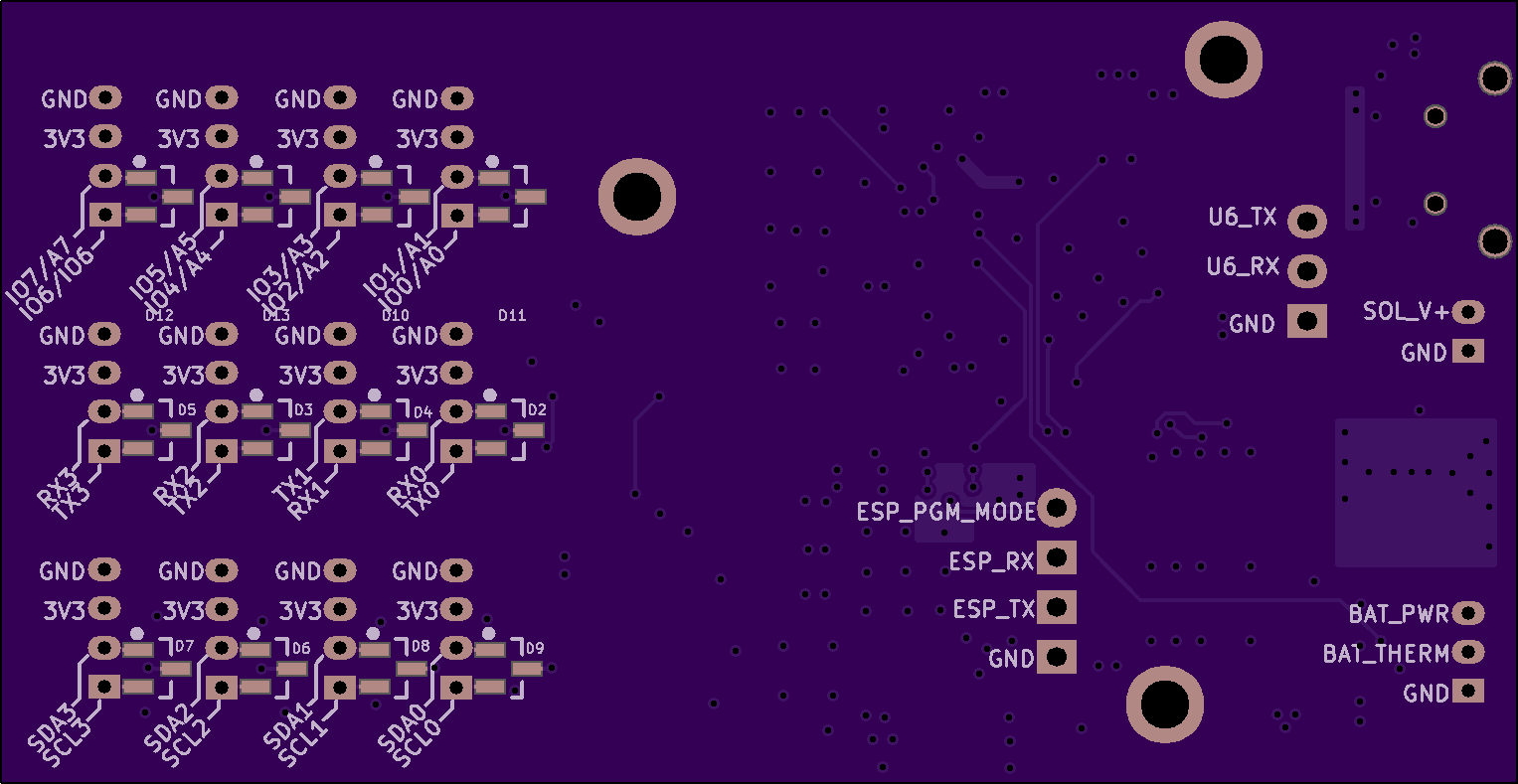
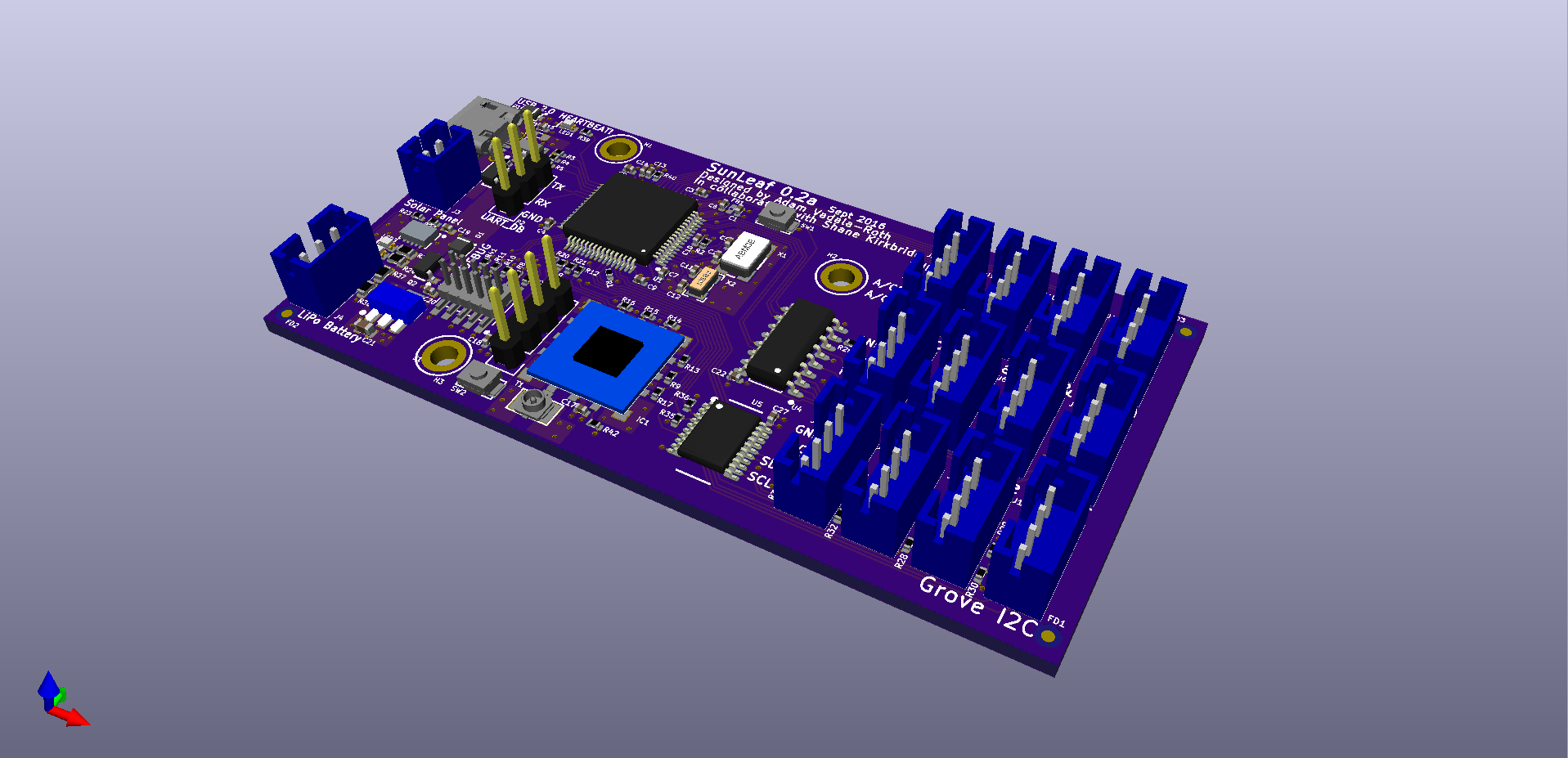
    Hello!! The new SunLeaf hardware is getting ready for fabrication finally after some more tweaking and preparation. So as for fabrication of the next revisions SunLeaf version 0.2a (a = alpha) the plan is to do another prototype run of 3-10 boards and hand assemble them testing desired functionality and noting fixes for future revs. At the same time I've been running the SunLeaf 0.2a through Macrofab's wonder fabrication platform. The goal of this new design is to get a hardware module that is working problem free with all our desired features functioning then to scale up and produce a pile of boards for beta testers and users !

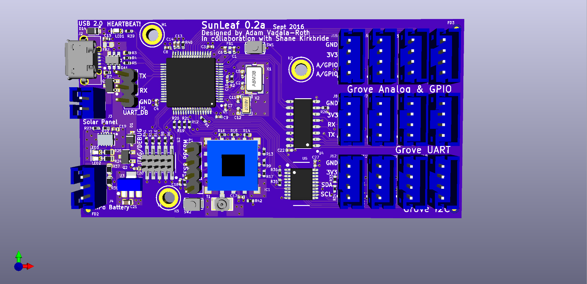
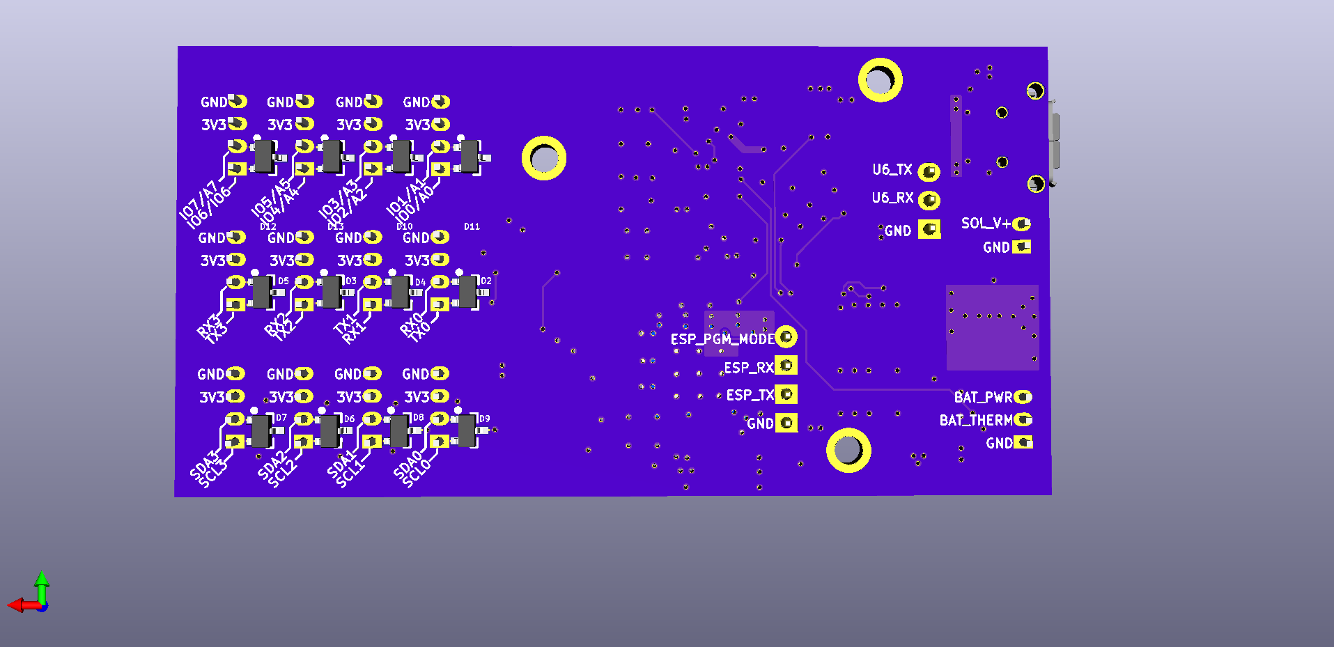
    So for the prototype run, we are currently evaluating fab house for quickturn manufacturing. I typically use OSHPark for all prototypes but as time keeps going by it might be cutting it close with their services. Either way I created renders of the new board with there fab:

    Top View:

    Bottom View:

    The board is only about 2 dollars more expensive than the last revisions with an order total of around 47 dollars for a round of 3 from OSHPark. The necessary adjustments in size didn't hurt us on cost very much wihich is great.

    Moving onto the bill of materials, everything for the prototype BOM comes from Digikey with the expception of the ESP-09 module that is ordered from a user on Tindie who imports them to the US. The BOM is simple it just explains the parts used, how much one costs in qty of one and the overall cost to build one SunLeaf. If you are feeling ambitious have at it, order some parts and boards and solder them up we'd love to hear about it. Anyways here is the BOM:

    DesignatorMFR #Digikey#Cost (QTY 1)QuantityBuild Cost QTY
    IC1ESP_09https://www.tindie.com/products/George/esp8266-esp-09-module/?pt=full_prod_search4.9814.98
    FD3,FD2,FD1FIDUCIAL030
    U2BQ24210DQCT296-28738-1-ND3.1913.19
    U5PCA9518DBQR296-22764-1-ND1.9411.94
    D1BAT20JFILM497-3381-1-ND0.4410.44
    J11,J16,J9,J12,J13,J15,J14,J10,J8,J7,J6,J5B4B-PH-K-S(LF)(SN)455-1706-ND0.24122.88
    D7,D6,D8,D9,D11,D12,D13,D10,D3,D5,D2,D4PESD3V3L2BT,215568-4041-1-ND0.47125.64
    DA1ESDA6V1BC6497-6635-1-ND0.4210.42
    Q2,Q1DMG2307L-7DMG2307L-7DICT-ND0.3820.76
    X2ABS07-32.768KHZ-9-T535-9544-1-ND0.7710.77
    X1ABM3B8.000MHZB2T535-9720-1-ND0.6610.66
    D14RSB39VTE-17RSB39VTE-17CT-ND0.4510.45
    J3B2B-PH-K-S(LF)(SN)455-1704-ND0.1710.17
    J4B3B-PH-K-S(LF)(SN)455-1705-ND0.1910.19
    T11909763-1A118077CT-ND0.5810.58
    U474HC4052D568-1456-1-ND0.510.5
    U1STM32F446RET6497-15376-ND8.5918.59
    J120021121-00010C4LF609-3695-1-ND0.810.8
    R42,R40,R3,R1RC1005F103CS1276-3431-1-ND0.140.4
    H2,H1,H3M2.5_Hole30
    R41,R39,R23,R18,R15,R14,R16,R26,R8,R6,R2,R11,R10RC1005F102CS1276-3430-1-ND0.1131.3
    FB2MI0603K300R-10240-2373-1-ND0.110.1
    SW1,SW2B3U-1000PSW1020CT-ND1.1822.36
    P2CONN_01X0310
    LED1LTST-C193TBKT-5A160-1827-1-ND0.4710.47
    R37,R38ERA-3AEB3741VP3.74KDBCT-ND0.6321.26
    R9,R20,R19,R17,R12,R21,R13RC1005F201CS1276-3959-1-ND0.170.7
    R36,R35,R29,R30,R31,R28,R27,R33,R32,R34RC1005F472CS1276-3466-1-ND0.1101
    R22RC1005F4870CS1276-3991-1-ND0.110.1
    R4,R5CPF0402B22RE1A102720CT-ND0.5621.12
    R7RC1005J473CS1276-4416-1-ND0.110.1
    C4,C6,C14,C8,C10,C15,C3,C9,C1,C22,C27,C7,C17,C18CL05B104JP5NNNC1276-1506-1-ND0.1141.4
    C11,C12CL05C180GB5NCNC1276-1647-1-ND0.120.2
    C13CL05A475KQ5NRNC1276-1481-1-ND0.3610.36
    C2,C5CL05C090CB5NNNC1276-1616-1-ND0.120.2
    FB1BLM15HG601SN1D490-3998-1-ND0.2310.23
    P1CONN_01X0410
    C21CL10A106KQ8NNNC1276-1038-1-ND0.2410.24
    C20,C19CL05A105KA5NQNC1276-1445-1-ND0.2420.48
    LED2LTST-C191KGKT160-1446-1-ND0.2910.29
    LED3LTST-C191KFKT160-1445-1-ND0.2710.27
    U3AZ1117CR-3.3TRG1AZ1117CR-3.3TRG1DICT-ND0.4110.41
    J2475890001WM17143CT-ND0.8110.81
    R24,R25RC1608J202CS1276-5069-1-ND0.120.2
    PCB CostOSHPark (3 Boards)48.216.116.1
    BOM Total Cost63.06

    If you wish to view it as a google spreadsheet the following link will do just that: https://docs.google.com/spreadsheets/d/1kv7WRCuP9jof3ieIvjWm7yBUWpwseHQou-YMSgxwjEM/edit?usp=sharing

    So there we are, we have a new board a BOM, and prepping to order, just some more final checks. That's all for now, but expect more posts this week!

  • More Hardware Updates, 0.2a Readying for the Fab

    AVR09/29/2016 at 22:09 0 comments

    So its been a short while since we discussed SunLeaf hardware. there's actually be a lot done since the last update readying the PCB ready for fabrication. In the last few weeks I have been slowly cleaning up the PCB routing, eliminating design rule errors, and making sure all reference schematics were followed.

    Most of the work though was spent getting the board ready to fab with KiCAD and its built in plotting tools. I wanted to put the board through serious design rule checks to ensure that it fabricates without any issues that could cause problems down the line. Also while retooling the boeard and squashing DRC violations, I added three M2.5 mounting holes, so that a new 3D case can be easily designed and 3D printed.

    Another I updated was labeling, and fiducials. The board feature a lot more labeling of pins and and connectors. Everything from the sensor inputs, battery, solar, USB. JTAG is labeled, bottom side of board features labeling of each pin. The fiducials are for automated assembly, so pick and place machines know the orientation of the board when placing components as sometimes the board can be rotated by the machine during assembly etc. Another fix was adjusting all copper pours that re nearby each other to not overlap and to pour with the right amount of clearance so as to not violate the design rules. This sort of function is typically handled automatically in a professional design tool like Altium, not to say that KiCAD is not capable of professional work you just need to know what you are doing and do a lot of things manually, not that much of a problem, those of use that use a lot of open source software are used to these sort of things. More of the fixes include cleaning up of ESP-09 module, adding a larger ground pour beneath it and adequately stitching to the internal ground layer. The internal plane for power has also been cut beneath the antenna connector to cut down on interference with RF transmissions. Another update include a header to connect to UART6 on the STM32 for debugging over a USB serial converter. The JTAG connection was also cleaned up and a pullup resistor added to the JTAG reset signal, in the original SunLeaf the button reset pin was used for both JTAG and user reset, while it worked it was not the correct implementation and has been since corrected. BOOT1 pin has been pulled high with a 10K pullup and is now driveable by the ESP this correction is for the OTA programming functionality. On the ESP-09 CH_PD has been pulled high for ensure proper operation, deciding whether or not to have this controlled by the STM32 yet.

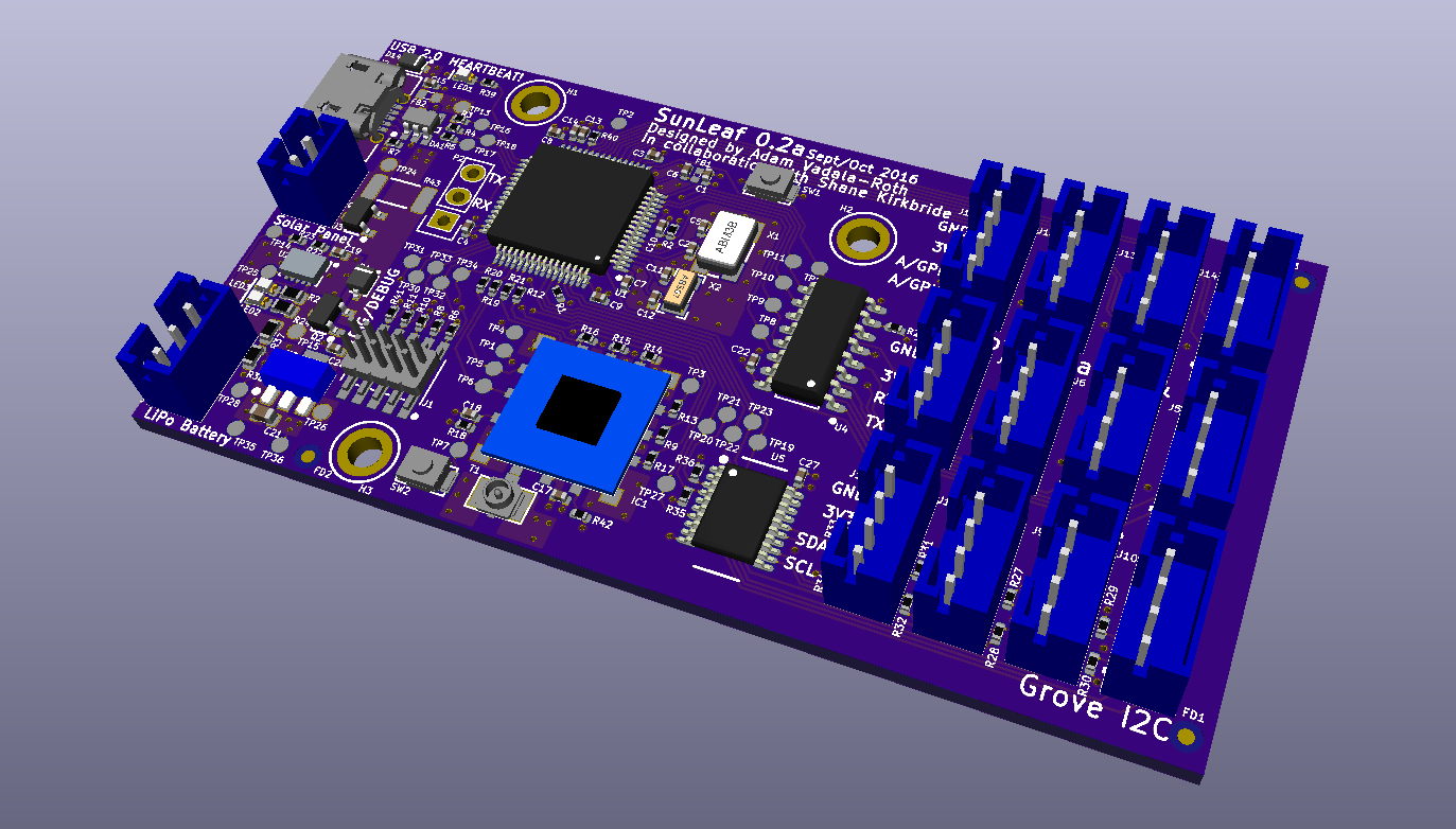
    Electrical things where not the only part of the work done on SunLeaf 0.2a. 3D models were added to more components for proper 3D rendering of the board. This is important for designing a new 3D printed case for the 0.2a revision. KiCAD does a great job at rendering and showing the board, its super smooth and very fast. Here are some pictures of the render:

    Top:

    Bottom:

    With that there are only a few more tweaks to do before fab, mostly adding test points. For testing this board the plan is to make two layer board with pogo pins tapping the connectors from the bottom. This method should eliminated the need for most test points, either that way ore the board will sit upside down in the test jig. More on that stuff in the next update!!

  • Hardware Update: Rev2, OTA programming, and Battery Monitoring

    AVR09/19/2016 at 23:08 1 comment

    So it has been too long since our last update on the hardware. The last thing I mentioned related to the hardware was that rev2 of the SunLeaf was already underway in KiCAD, well its nearly done and here's what I did with it:

    - Implemented OTA (over the air) programming signal connections between the ESP8266 and STM32

    - Changed the ESP8266 module from the ESP-02 to the ESP-09, more pins needed for OTA.

    - Implemented battery monitoring with a simple voltage divider, allowing battery voltage to be monitored.

    - Moved the ESP module and supporting components from the bottom to the top of the PCB

    - ESP module no longer has UART between STM32 as jumpers, they are directly wired with a throughhole connector for ESP code flashing inlined with the signals

    - Sensing conenctors changed to all 4 pin based ones.

    - Chaned the position of the power and ground on Grove connectors to be correct, they were swapped in version 1.

    - Overall PCB size has been slightly increased to move ESP to the top and accommodate changing the 3 pin JST connectors to 4 pin ones for the analog and expansion connectors.

    - Battery controller circuit has been revised to more efficiently dissipate heat.

    - LDO switched to a smaller package to save board realestate.

    - TVS diodes on sensor inputs rotated 180 degrees to keep them far away from the board edge.

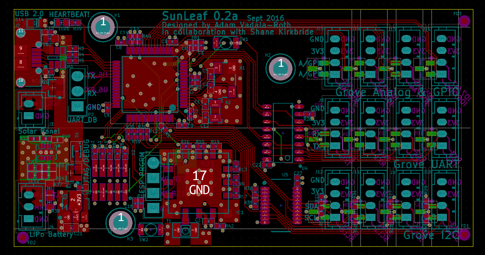
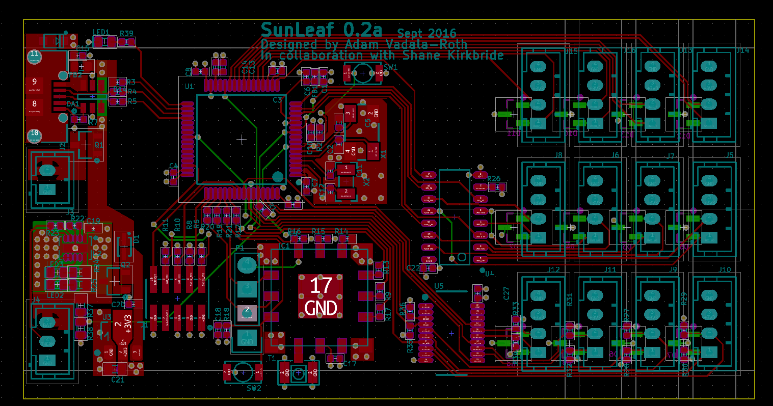
    Now the PCB isn't 100% finalized but its about all but done having implemented the above, I might be forgetting some things but that's the jist of it, I'll have more updates on that next post. So without further do, SunLeaf Alpha 0.2 :

    The schematic has also been drawn to be more readable in this revision.

    Schematic Renders:

    So that's where we are at with SunLeaf rev 2, next I think I'm going to add mounting holes and some logos and thats about it, so its done for the most part. There is also tad bit more testing with the solar charging section we want to do before fabricating the board, that will be touched upon in the next post on hardware.

    So OTA programming, I mentioned in the title, so yeah we are going to implement over the air programming of STM32F446RET6 our main processor over UART with the ESP-09 ESP8266 module. The STM32 has a bootloader that supports loading of firmware over any of its UART ports, this functionaility is toggled via the processor reset pin and toggling the two BOOT pins on the processor, this allows the ESP to restart the STM32 into bootloader mode and load the firmware over UART. All this has been set up in this design revision, we consider it a major feature upgrade over the rev 1.

    We got a few more updates on firmware, functionality, and application from my great teammate Shane so stay tuned for that. As for this post that's all folks!

  • Hardware Update

    AVR09/13/2016 at 02:18 0 comments

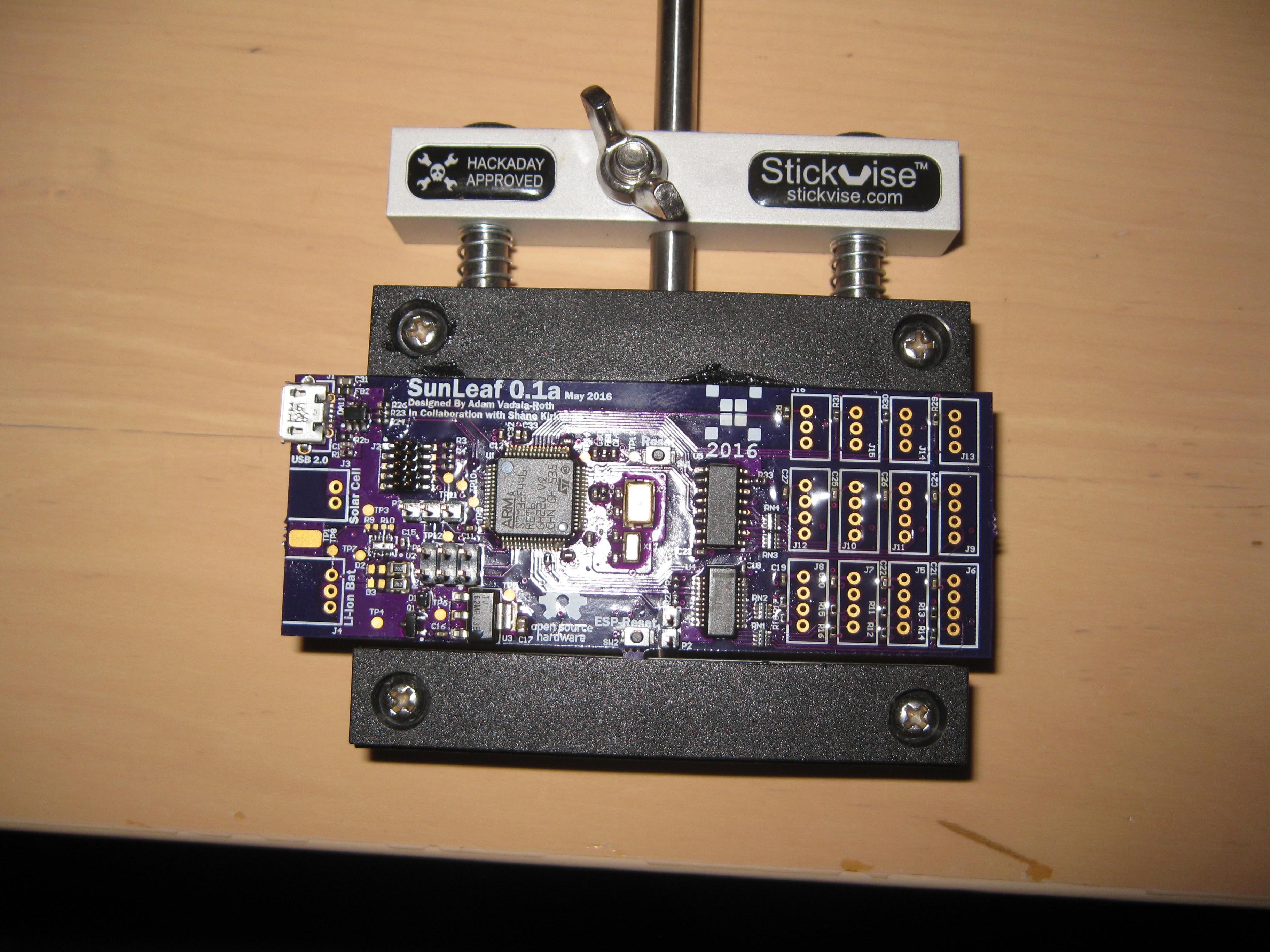
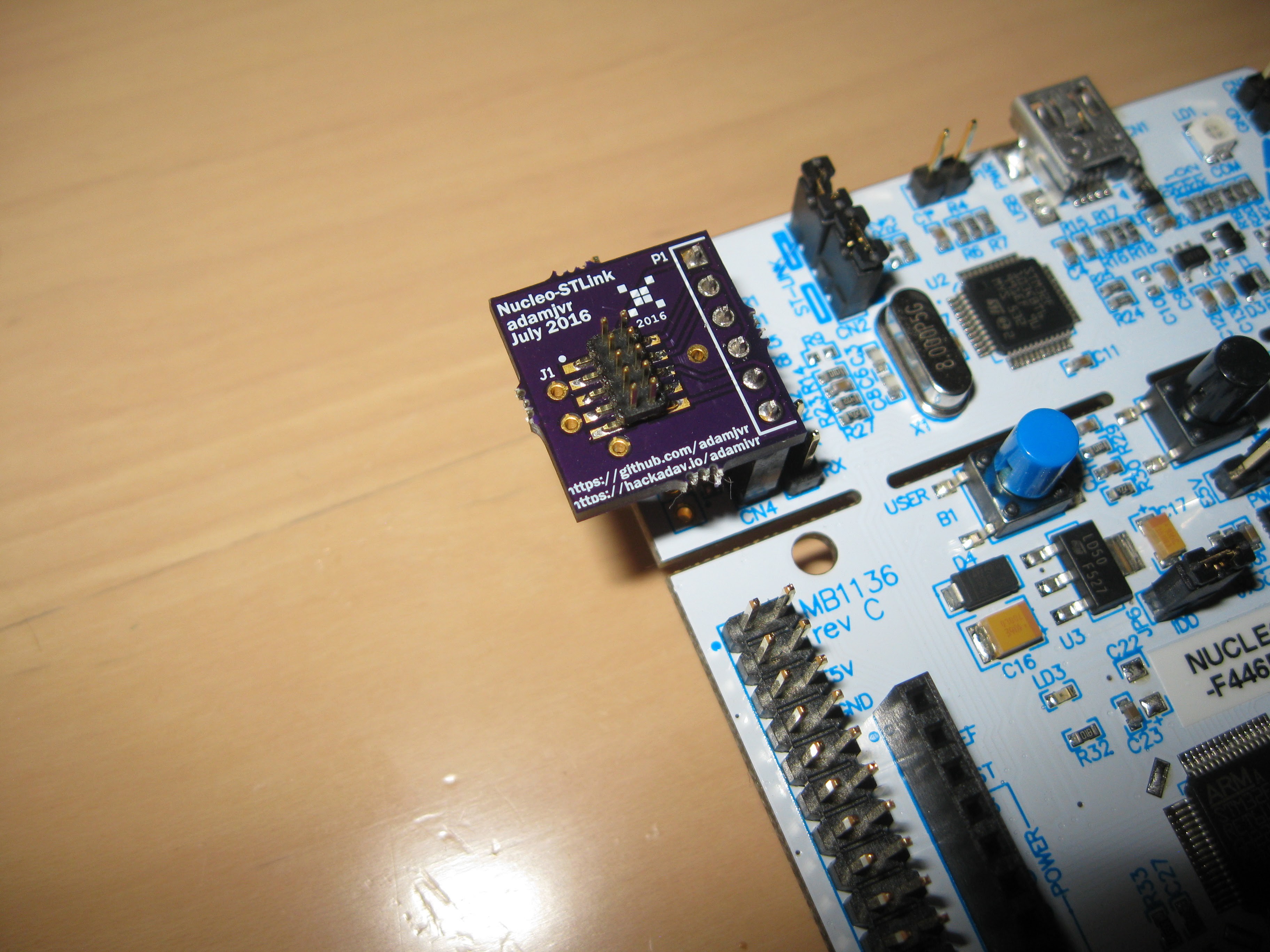
    So its been a while since we talked about the SunLeaf hardware. There has been quite a bit done since the last post. In the last update I showed what I had populated so far on the SunLeaf 0.1a PCB. The populated sections included, USB connector and suppression, STM32 circuitry, sensor muxing circuitry, ESP-02 module, programming headers, and transient suppression circuitry. With all that populated the SunLeaf was ready for testing but I realized that I didn't have a way to connect the ST Nucleo board to the SunLeaf to program it.

    My solution was to make a small adapter PCB that lets you hook up the STLinkV2 integrated into the ST Nucleo board to any target board over the ARM Cortex M debug port (10 pin 1.27mm pitch header ). The adapter took 10 days to make at OSHPark which delayed testing. After assembly I was able to put it on my ST Nucleo, pull the jumpers and presto STLinkV2 for cheap:

    Moving on, last update I mentioned that the footprint to the solar battery charge controller IC was flipped making it not possible to populate and function. Well I made a mistake in my analysis turns out that the footprint was just fine, I only labeled pin 10 as pin 1 with the dot marker on the PCB which made me think I got it wrong during assembly. So I decided to populate the remainder of the PCB and start testing it. The fully assembled SunLeaf 0.1a :

    So with the fully populated SunLeaf I started testing things down at the basics. First I tested power, I plugged it in via USB, and checked it with a volt meter. The MOSFET for switching from battery to USB power for feeding the 3V3 regulator worked successfully. The LDO was also pumping out the correct 3.3V as expected.

    Next I decided to test programmability of the two systems on board the SunLeaf. The SunLeaf is effectively a dual processor board with the STM32F446RET6 and the ESP8266 (ESP-02 Module) linked over UART serial. Their link is jumperable on this revision, so the ESP8266 can be programmed over its UART port. So to begin I wired up the ES8266 to my Adafruit FT232H breakout, wired up the SunLeaf to the Nucleo :

    To test the ESP8266 I simply just use the Arduino IDE configured with the board support package for the ESP8266, and I just attempted to flash the blink program. Unfortunately I was unable to flash any code or talk to the ESP8266. The module I used is an ESP-02 which apparently has multiple footprints and different setup circuit requirements. I solder pins to another one I had and breadboarded it but could not get it to talk serial or program. So right now its not looking good for this module. What I'm gonna do now is order a few other ones that will fit my requirements and I will breadboard test each one and make sure to use one that has an agreed upon footprint. It also turns out we need more pins on the ESP anyways, because we want the STM32 and the ESP8266 to toggle eachother's reset pins and have a sync pin, this is for when we implement over the air updates for the firmware on both chips. So on the next revision there will be a different ESP8266 module. Yes I know the ESP32 is out and I even made libraries for it: https://hackaday.io/project/13483-esp32-kicad-library but its just so new we are not sure the existing firmware for the ESP will be able to be compiled for it. I'm thinking hardware version 3 or 4 will feature the ESP32.

    Next off was to test the STM32F446RET6, the main processor. ST Microelectronics makes this sort of stuff incredibly easy. They have a awesome STLink utility program that lets you flash code, verify, and do lots of testing stuff with your STM32 target projects. You can find it here if you want: http://www.st.com/content/st_com/en/products/embedded-software/development-tool-software/stsw-link004.html . So with the Nucleo hooked to the SunLeaf I used the utility's connect to target function and it successfully connected. So the STM32 started up fine, indicating that the reference design with my adjustments worked out ok. Next I wanted to test the serial,...

    Read more »

  • Basic Power Management

    shane kirkbride08/16/2016 at 14:36 0 comments

    Introduction

    One of the goals behind SunLeaf is to enable it run without external charge for at least 2 years. This means that power is a huge factor in making this successful. We think this is possible because both chips: the STM and the ESP both have low power modes. This is not the only consideration. We also need to consider the power source. The battery we will use is here: <insert link> and the solar panel is here <insert link>. The solar panel is small, however we will rely on an adaptive the sleep mode controller to regulate the power and the best times to take a measurement. Now that we have identified the major components we can start the beginning of a power budget to show this capability.

    Power budget

    STM32F446RET6ESP8266 ESP-02Support hardwareTotalsunits
    ModeMode
    Run6Run17050226mA
    Sleep3Modem sleep15018mA
    Stop3Light Sleep0.903.9mA
    Stand-by0.00028Deep Sleep0.00100.00128mA
    Full Power0.7458W
    Sleep Power0.0099033W


    Power management in software

    The STM32F446RE can be put into a sleep mode and then woken up using an internal interrupt in the programming:

    Ticker post_data;
    .
    .
    .
    //lots of code here...
    .
    .
    int main(){
    .
    .
    //lots of code here...
    .
    .
    post_data.attach(&post, 60.0); // the address of the function to be attached (post) and the interval (2 seconds)...this will wake up the STM
     
    while(true){      
          if(posted)
          {
            debugSerial.printf("sleeping...\n\r");
            posted = false;
            esp.Sleep();  //put the esp to sleep
            ESPisAsleep = true;
            led2 = 0; //turn off all other power and sensors
            
            sleep();       //then sleep
          }else{
            LCD_D7 = 1;
            led2 = !led2;     
            wait(0.5); // give everything a half-second to wake up
          }
      } 
    
    }

    So basically we always keep the STM32F446RE in sleep mode unless there is an interrupt. The frequency of the interrupt is given in the second argument. This value can be adapted to optimally send environmental data while preserving the battery life. Details on this will be given in another log on complex power management. You can also see that we send the esp.Sleep() command to the ESP. esp.Sleep() did not originally come with the STM-Client so we had to add it. Here's how we did this. I'll review what was done on the STM32 then I'll review the ESP-Link Code changes. First we added to the STMClient.cpp file the following code at the bottom:

     //look in cmd.c for this. Puts ESP to sleep until a fall edge triggers on RST for it to reset.
     
    void STMClient::Sleep(void){
      Request(CMD_SLEEP, 0, 0);
      Request();
    }
    This code calls the 'Request' function. Within STMClient.h there is a typedef. It MUST MATCH THE ONE IN THE ESP-LINK CODE: line for line.
    // Enumeration of commands supported by esp-link, this needs to match the definition in
    // esp-link!
    typedef enum {
      CMD_NULL = 0,     // null, mainly to prevent 0 from doing something bad
      CMD_SYNC,         // synchronize, starts the protocol
      CMD_RESP_V,       // response with a value
      CMD_RESP_CB,      // response with a callback
      CMD_WIFI_STATUS,  // get the wifi status
      CMD_SLEEP,        // Go to sleep
      CMD_CB_ADD,       // add a custom callback
      CMD_CB_EVENTS,    // ???
      CMD_GET_TIME,     // get current time in seconds since the unix epoch
      //CMD_GET_INFO,
    
      CMD_MQTT_SETUP = 10,
      CMD_MQTT_PUBLISH,
      CMD_MQTT_SUBSCRIBE,
      CMD_MQTT_LWT,
      CMD_MQTT_EVENTS,
    
      CMD_REST_SETUP = 20,
      CMD_REST_REQUEST,
      CMD_REST_SETHEADER,
      CMD_REST_EVENTS
    } CmdName;
    This makes the CMD_SLEEP call '5'. This is useful for debug within the ESP-LINK code. What this basically does is it tells the esp to go find command '5' and execute it.Those are the required changes on the STM. You can see how easy it is to add a custom change. In the future there will likely be a few more types of sleep modes and other ESP-STM interface commands.

    The ESP-LINK required a few more additions as well. All of these additions occur in the /cmd/ directory of the ESP-LINK Code.

    First we had to add the CMD_SLEEP handler in handlers.c:

    // Command dispatch table for serial -> ESP commands
    const CmdList commands[] = {
      {CMD_NULL,            "NULL",           cmdNull},        // no-op
      {CMD_SYNC,            "SYNC",           cmdSync},        // synchronize...
    Read more »

View all 25 project logs

  • 1
    Step 1

    Understand the caveat of these instructions and read all the logs

    This is a set of instructions on building the open source SunLeaf module from scratch. There are some complicated engineering concepts in this product but you really don't need to understand them all to have this module built. Since it is hardware you'll have to have some money to buy the equipment. But it is less than $100 for a module. We also encourage you to read all of our logs...this is where the real instructions exist.

  • 2
    Step 2

    Get the software..it's all free

    The hardware was developed in KiCAD so you'll need to download that from here: http://kicad-pcb.org/

    You'll need a Linux OS for the ESP compiler. I liked Ubuntu until they sold out: https://www.ubuntu.com/. There are a few specific logs on setting up the ESP Compiler so I won't go into that here.

    You can run the MBed compiler in any web browser: https://developer.mbed.org/. There are a few logs on programming the STM so I won't go into that here either.

    You'll need to set up a thingspeak.com account: https://thingspeak.com/

  • 3
    Step 3

    Pull the projects

    We kept everything on Git:

    Hardware is here:

    https://github.com/HydroPWNics/SunLeaf

    The ESP firmware is here:

    https://github.com/HydroPWNics/SunLeaf-ESP8266

    The STM32 Firmware is here:

    https://github.com/HydroPWNics/SunLeaf-STM32 (working)

    or here:

    https://developer.mbed.org/users/ShaneKirkbride/code/STM-Client/ (latest)

    Beaware there are some compiler companies (Keil and IAR) that want to sell you this stuff for $10K. You really don't have to buy that hardware if you can read the STM Manual and google. But if you don't want to read or google a little then go ahead an pay your $10K.

View all 9 instructions

Enjoy this project?

Share

Discussions

yOyOeK1 wrote 02/01/2023 at 10:32 point

Nice

  Are you sure? yes | no

erifaole wrote 09/07/2021 at 17:50 point

This is amazing feature I never watched this type of environmental monitor any where. You can see my Fiber Installations project here.

  Are you sure? yes | no

marchandoliver wrote 08/01/2018 at 08:06 point

big resources in technology !!!!!!! via SUN LEAF

please update me the cost of the hardware .

  Are you sure? yes | no

Nhan Nguyen wrote 05/09/2017 at 10:28 point

Hi Adam, it's a pretty cool project and congrats! I have a similar project to build a device capturing environmental factors such as: CO, Light, Noise, Dust, etc. so I'm wonder if SunLeaf V2 is released yet and available for sale? I understood it's an open-source project (I love it) and I want to help you out. Thank you!

  Are you sure? yes | no

oshpark wrote 07/19/2016 at 12:52 point

Congrats on being a winner for the Citizen Scientist portion of the Hackaday Prize!

https://hackaday.com/2016/07/18/hackaday-prize-20-projects-that-make-us-all-citizen-scientists/

  Are you sure? yes | no

shane kirkbride wrote 07/26/2016 at 12:21 point

Thanks!

  Are you sure? yes | no

Someone wrote 06/26/2016 at 11:54 point

Great project. One question is why are you using an LDO instead of a more power efficient DC/DC converter? 

  Are you sure? yes | no

AVR wrote 06/29/2016 at 18:33 point

We are using an LDO instead of DCDC converter to protect the ESP8366 ESP-02 module from noise since its an RF module. Also the system battery is going to be 3.7V and the power system onboard is 3.3V so we are only dropping the input down by 0.4V. 

  Are you sure? yes | no

Similar Projects

Does this project spark your interest?

Become a member to follow this project and never miss any updates