-
Software updates
12/28/2016 at 17:19 • 0 commentsFrom software side all the basic functionality works now:
- SDS011/LCD/DHT22 drivers are functional
- OTA flashing is working
- Wifi AP mode for configuration
- simple HTTP configuration panel allowing changing WIFI configuration, ThingSpeak API key, etc.
- ThinkSpeak data upload
Things left to be done:
- Setting configuration for multiple wifis
- Scanning available WIFI networks in settings panel
- firmware upload using HTTP panel
- sensor data aggregation in case of network failure
- code cleanups
-
Some updates
12/25/2016 at 23:29 • 0 commentsSo there's another winter and another wave of terrible air quality in my city. This got me some motivation to find some time and move this project forward. I ordered another bunch of PCBs, this time with ground plane fixed, soldered testing board and done some testing. All the basic functionality seems to be working.
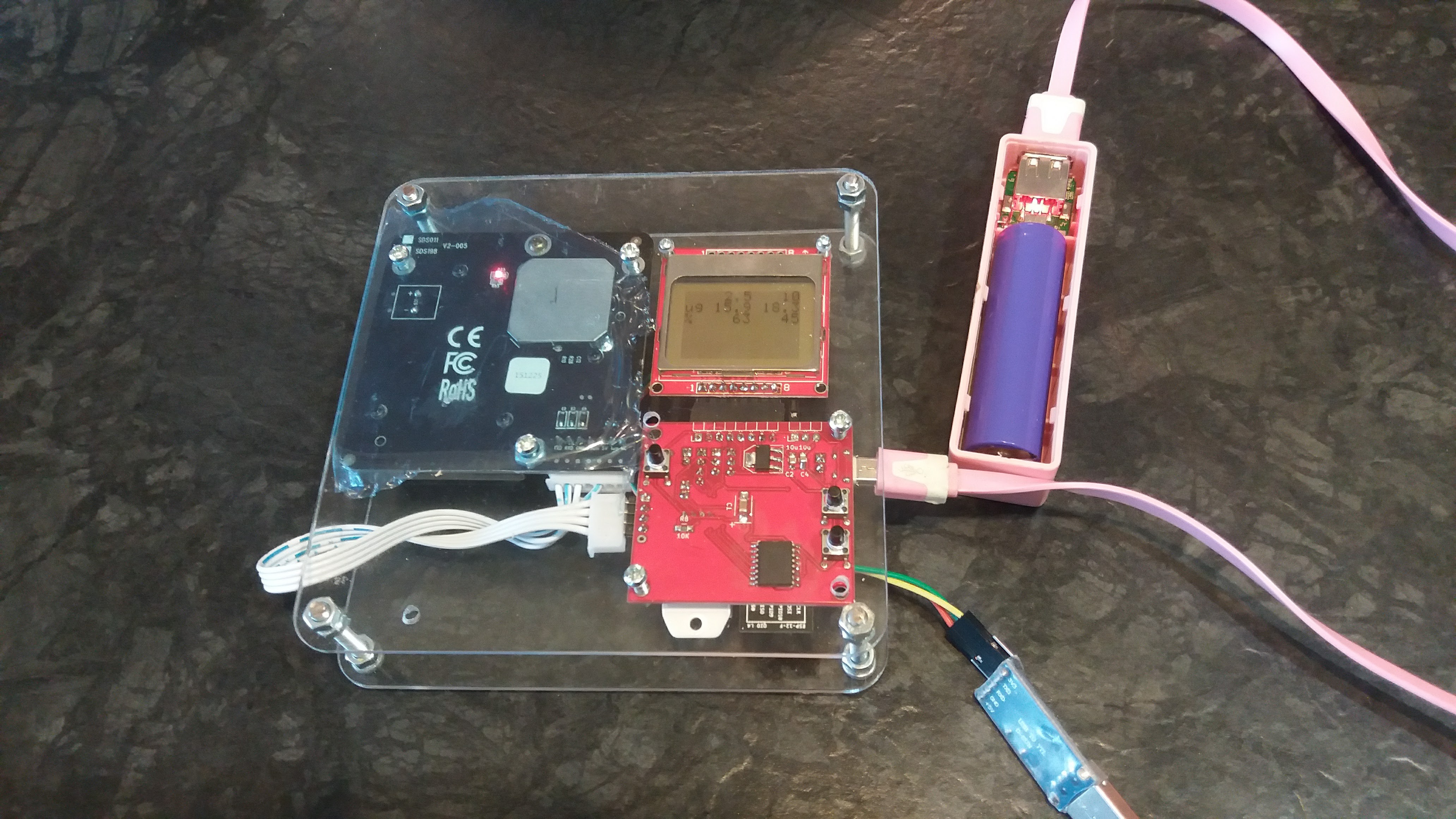
My friend asked me if I could make him a copy of this project which motivated me to actually put everything together, including enclosure. Here's how it looked:
The placement of the holes on a plexi has to be changed a little bit so that it would be possible to fit a powerbank. Then I want to order lasercut plexi sheets with proper holes so I don't have to drill them manually any more. But overall, this is much more handy to carry around now :)
PCB
Here's the list of things I have to change for next revision of the PCB:
- LCD reset works OK from PCF8574 so P4 connector can be removed
- DHT can't be driven from PCF8574 because of the tight timing constrains, P6 can be removed
- Interrupt line of the PCF8574 should not be connected to GPIO2 since this pin should not be pulled low while booting. I guess I could use GPIO14 instead and connect DHT22 to GPIO2 (since it's working with a pullup)
- DHT22 footprint is wrong, I have to fix it. Pin spacing is not right. Fortunately it's possible to solder it anyway with some bending
Software
In order to flash the board it is required to disconnect SDS011 sensor (it shares the same UART). This is problematic once it's in enclosure. To overcome that I've added basic support for flashing the board over WIFI. To enter this mode, SET button has to be pressed and hold just after restarting the device (but since it pulls GPIO2 down it CAN'T be hold while resetting the device). I've also added simple DHT22 library and some code to display humidity and temperature on the display. 2 most important things left to be done now are:
- configuration mode (using AP mode)
- data push (so that I can actually use wifi of the chip which is the main purpose of this project actually)
Further actions
I borrowed SDS011 from my friend so now, having two of them, I will be able to test if different sensors will produce similar results. In order to do that I first have to solder another unit and prepare another case. I would also like to order another SDS011 for me so that I could finally put one in constant operation leaving other one for development.
-
PCBs arrived
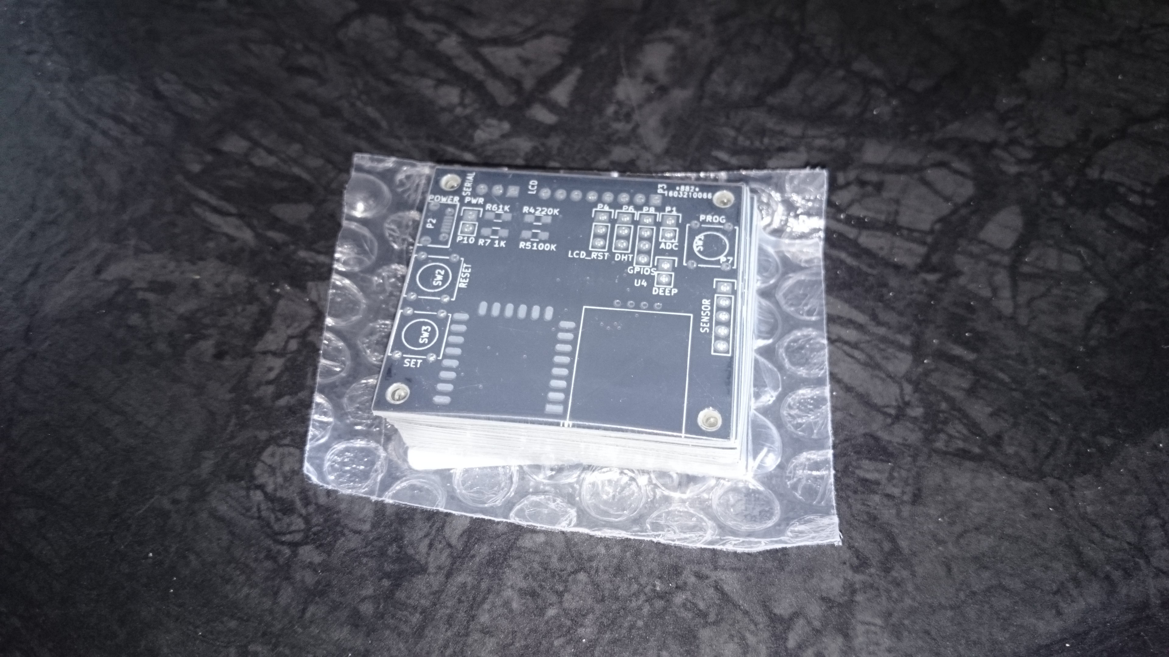
04/20/2016 at 07:59 • 0 commentsAfter exactly a month of waiting, first version of PCBs arrived. For the first time I used "new site" from dirtypcb service. It's experimental and they say it's still buggy but it did work fine for me. 11 PCBs, 5cm x 5cc for 11.95 USD including shipping to Poland. Here's how they look:
Now those boards are broken. I knew this in the morning, next day I ordered them but I couldn't fix this as they were already send for manufacturing 3h after I uploaded project files. Turns out it's not best idea to do last changes just before submitting the files for fab in the middle of the night. Now I will have to do some patching to connect grounds together. Other than that I just tested my footprint for DHT22 and somehow the spacing between its legs is a little too small. Fortunately this can be fixed by bending the legs a little bit. I'm very busy recently so I may not have enough time to solder them for some time.
-
Enclosure prototype
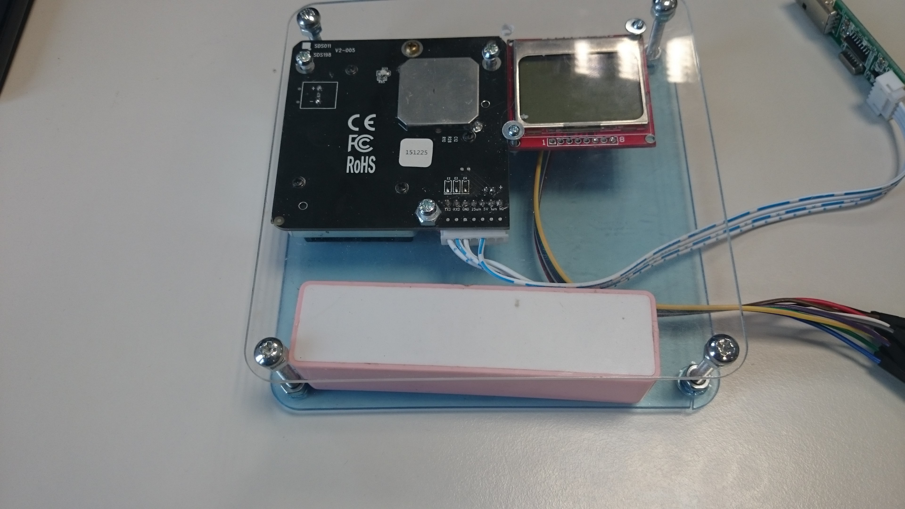
03/30/2016 at 07:18 • 0 commentsI ordered some laser cut 2mm plexi with the holes on the corners (no holes for the components yet as I'm not sure about the alignment yet). Using some screws instead of spacers and drilling some more holes by hand gives rough picture of how this is going to look like when finished:
I'm happy about how it looks. The whole thing is 13cm x 13 cm x 3cm but as can be seen it may probably be reduced a little. We'll see when PCB is done.
Cheap and simple air quality monitor
Cheap and easy to replicate internet connected PM2.5/PM10 monitor allowing you to check air quality inside and around your house.
 k
k

