Alex Hunt
-
Slow progress
05/18/2016 at 10:20 • 0 comments18 May 2016
Now that all my parts have arrived I can finally start work in earnest. The first step was to wire up all the various components. Having realised there aren't enough pins on an ATTINY85 to do what I wanted, I reverted back to using an ATMEGA168 for the bracelet side of things and an ATTINY85 for the sensor. My breadboards are now fully populated and all that's left is the coding.
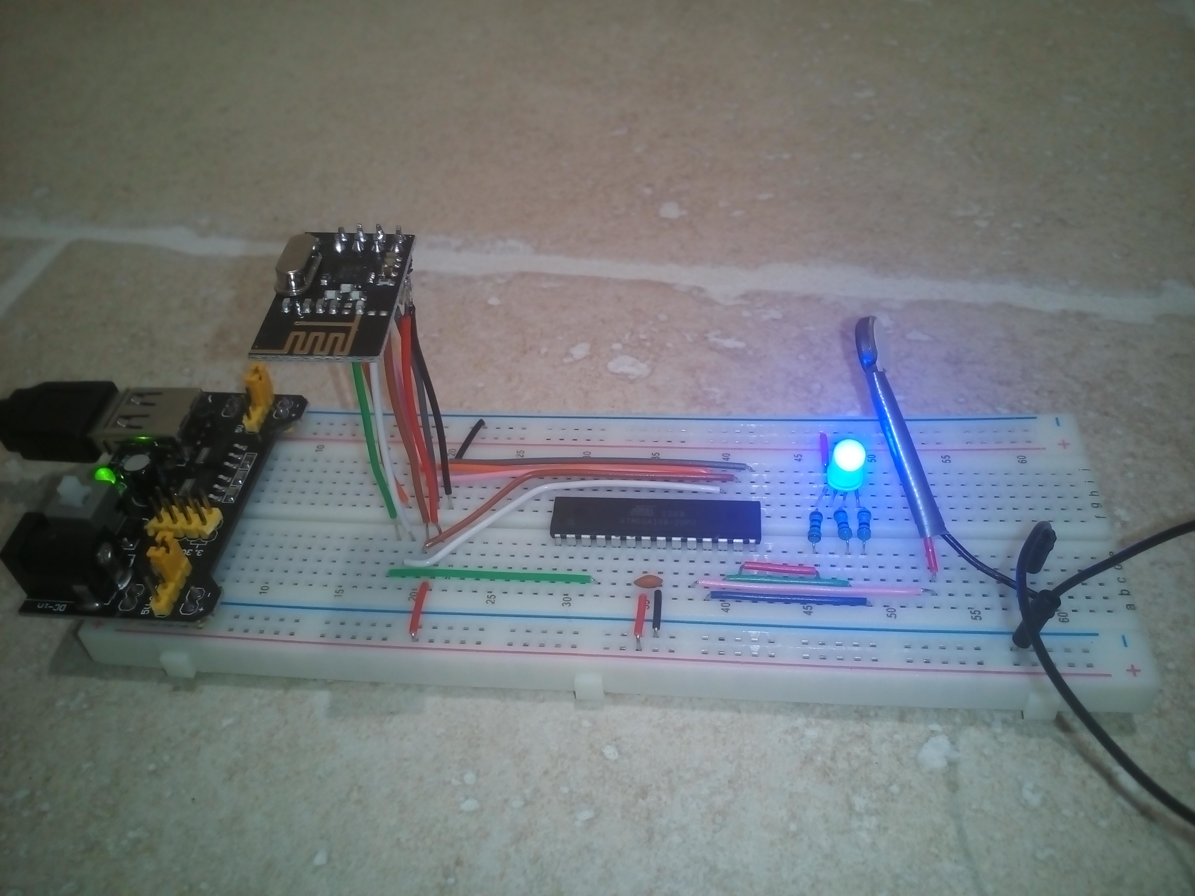
Bracelet components
![]()
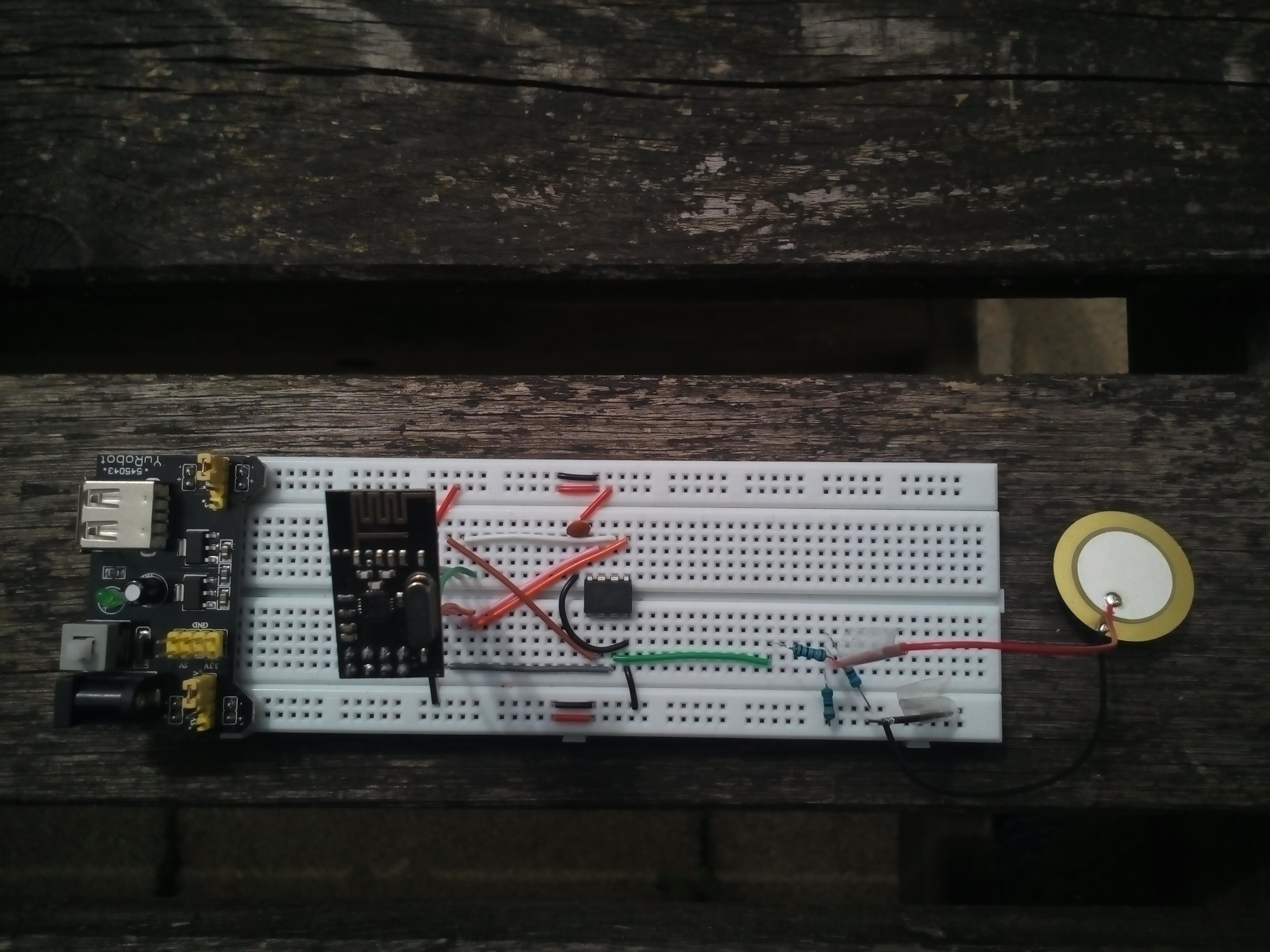
Sensor components
![]()
As to the coding, I have sorted out the various vibration and light patterns I would like for the bracelet and am now going about getting the NRF24L01 modules to talk to each other using this very handy tutorial from Gizmosnack here. I didn't want to go down the arduino route as I am a big fan of coding directly in C.
Circuit diagrams to follow soon!
-
3 April - Prototyping has begun!
04/04/2016 at 20:40 • 0 commentsWhilst the majority of my components are being shipped over from China (transcievers, MCUs, vibrating motor) I thought I would see how far I could get with configuring the piezo sensor.
A circuit diagram and code will follow. However, the sensor itself will hopefully be powered by an ATTiny85. In the meantime I shall be using an ATMega168-20PU as that is all I have to hand.
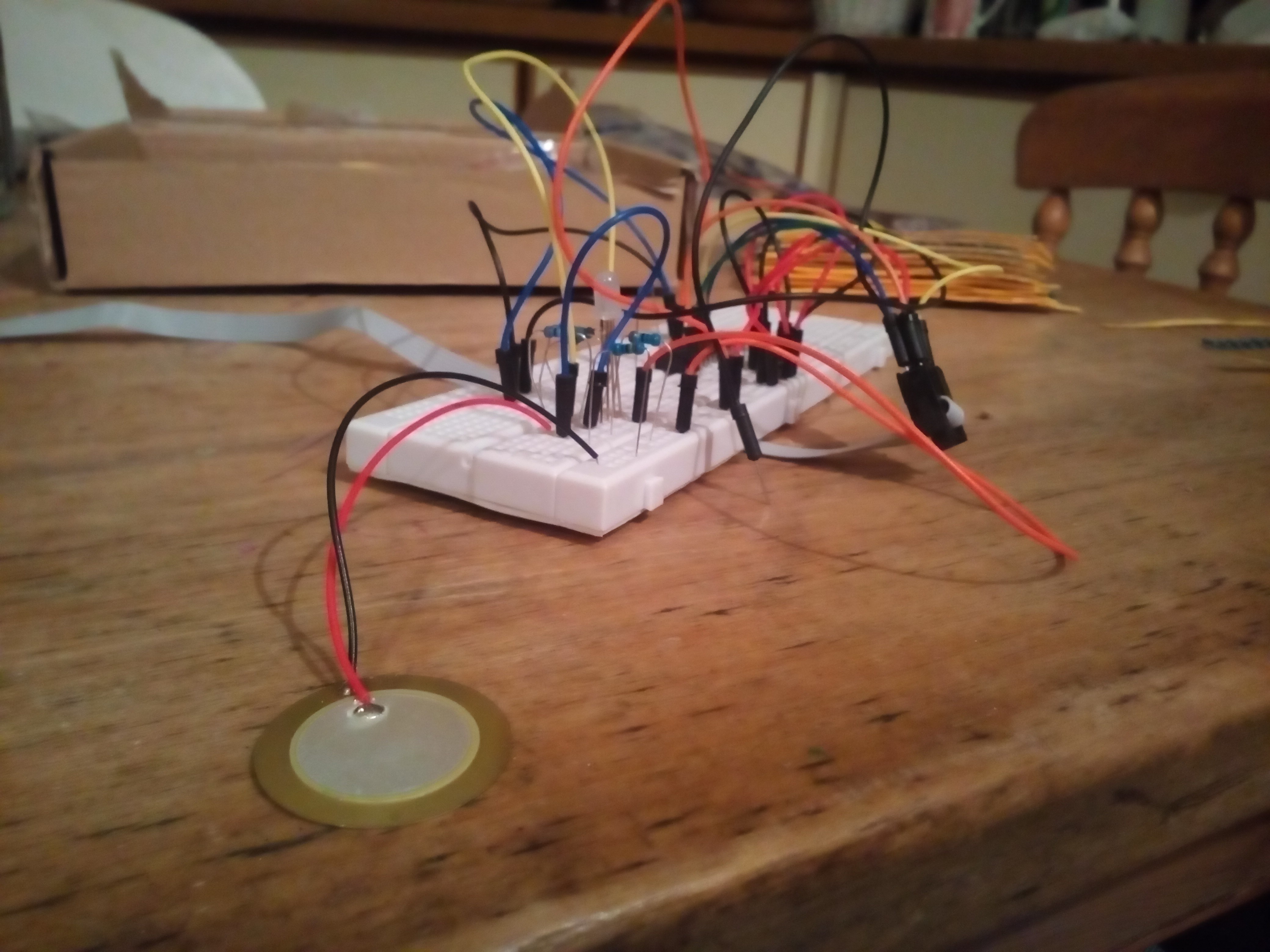
Having wired up the piezo sensor in a voltage divider setup (1MΩ resistors) and connected it to the Analog Digital Converter of the ATMega the piezo sensor could pick up fairly loud sounds (as indicated by a flashing LED) when taped to my kitchen table.
![]() However, the setup was nowhere near sensitive enough. Swapping out the resistors for 10MΩ resistors did the trick too well to the extent that it would pick up the workmen next door with their incessant hammering and off-tune singing (honestly guys - it's 11pm - go home already!).
However, the setup was nowhere near sensitive enough. Swapping out the resistors for 10MΩ resistors did the trick too well to the extent that it would pick up the workmen next door with their incessant hammering and off-tune singing (honestly guys - it's 11pm - go home already!).Sensitivity is clearly going to be an issue and will obviously depend upon what device the sensor is attached to. Conclusion - I need to order some potentiometers so that sensitivity can be altered on the fly. Back to eBay I go.
Shakelet - alerts for the hard of hearing
A wireless vibrating wristband to notify hard of hearing people of telephones, doorbells and other sound alerts.