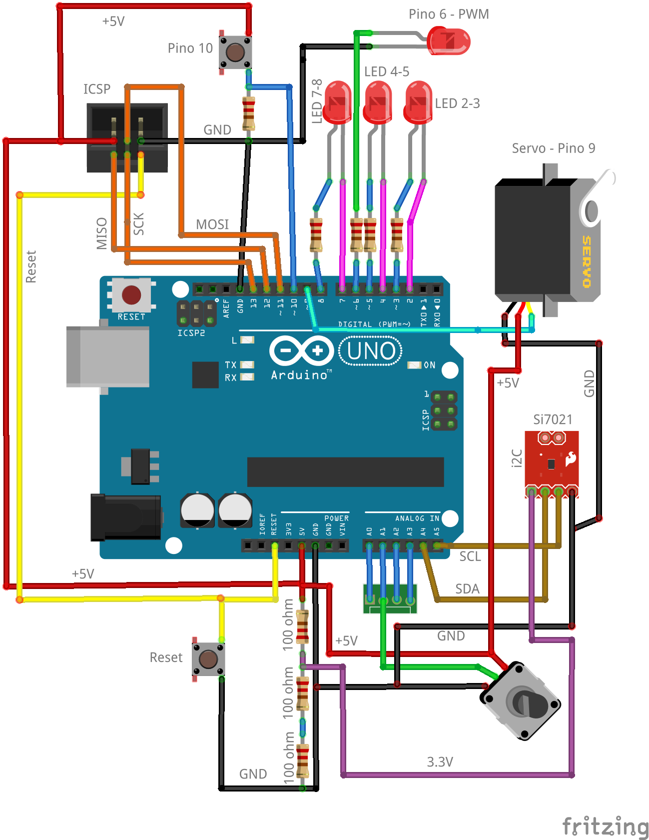
I came up with a nice (from my own standpoint) circuit arrange that tester each and every pin of my Arduino-compatible board:
- Pins 0 and 1 = Serial communication with a PC, through the "Serial.print()" command
- Pins 2 and 3= an LED connected between them
- Pins 4 and 5= another LED connected between them
- Pins 7 and 8= a third LED connected between them
- Pin 6= PWM test using a single LED + resistor
- Pin 9= connected to a 9G micro-servo-motor
- Pin 10= connected to a push-button
- Pins 11, 12 and 13= tested during bootloader burning to the ATMEGA328P-PU
- Pins A0..A3= a single potentiometer that can be "hardware-jumpered" to one analog input at a time.
- i2C communication on pins A4 and A5= an Si7021 temp+humidity breakout board.
In order to look at analog input and i2C data I have made an sketch for the Arduino under test: simply reading temperature and humidity from the Si7021, as well as analog voltage from A0..A3 and sending it over Serial port to the Arduino IDE serial console.
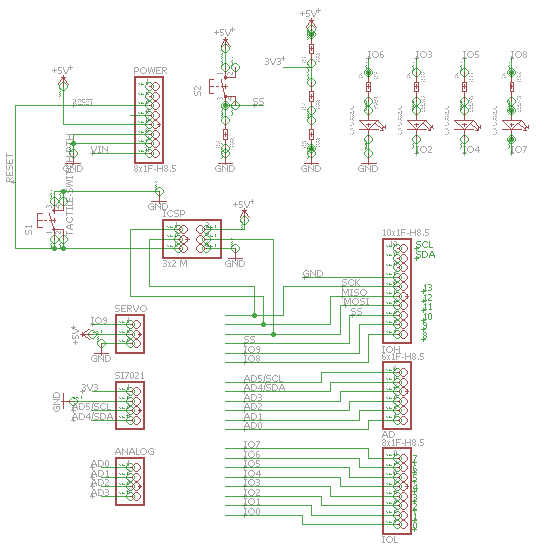
Here is a snapshot of the schematic diagram for this shield; note that you can download the full Eagle-CAD file from my GitHub, linked in the left-side of this page:

Here is a video of the system working:
 Clovis Fritzen


Usually for testing a system, you connect pins together for external loopack. When you toggle a pin, another I/O that it is connected to would try to look at the logic level to see if it matches. You can tests out if the I/O is stuck at logic '0'/'1' or floats. The internal peripherals e.g. PWM do not get damages as easily, but you can use a RC and ADC to confirm that the duty cycle can affect the output. This can be automated and report back errors.
https://www.eventhelix.com/RealtimeMantra/FaultHandling/hardware_diagnostics.htm