 Camilo Rojas
-
1Step 1
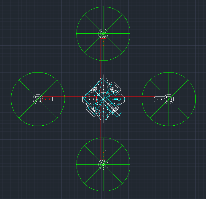
The first step is to define what the drone will include. I designed all the pieces and placed holes, in AutoCAD, according to the components list. I think the tubes are too long, but let's see what happens in flight, as it is easy to cut them again. I chose M3 screws, hence the holes have a diameter of 3.2 millimeters. The platform will be designed when I get the quadcopter to work.
![]()
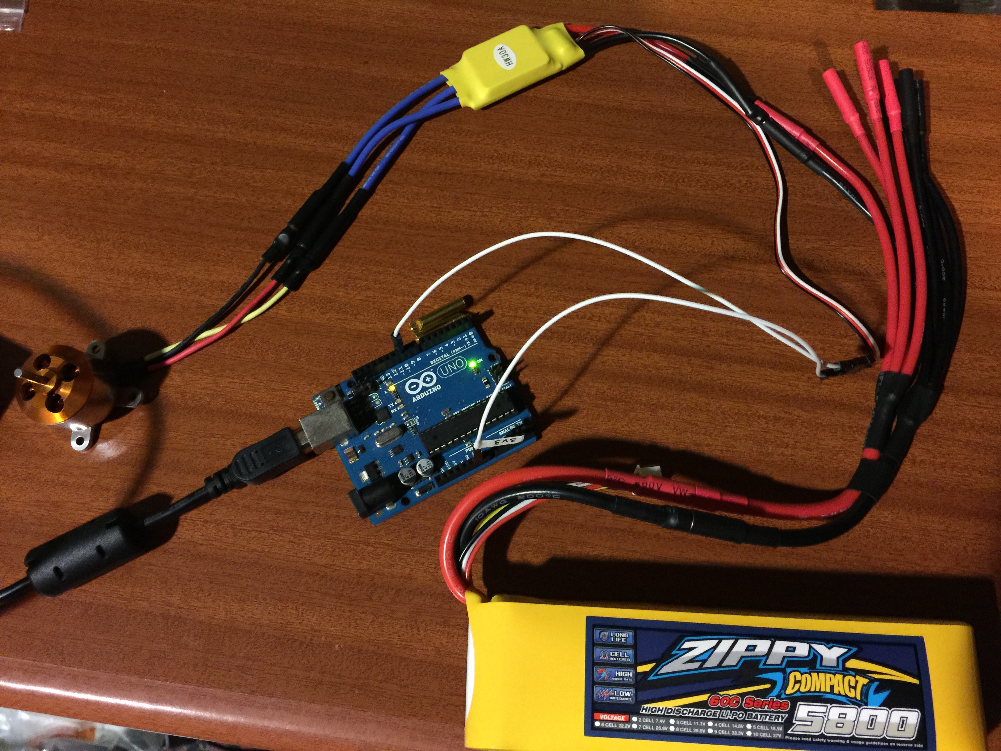
I successfully tested the ESC with an Arduino sketch and a potentiometer. Find the sketch inside the "ESC" folder in GitHub.
![]()
-
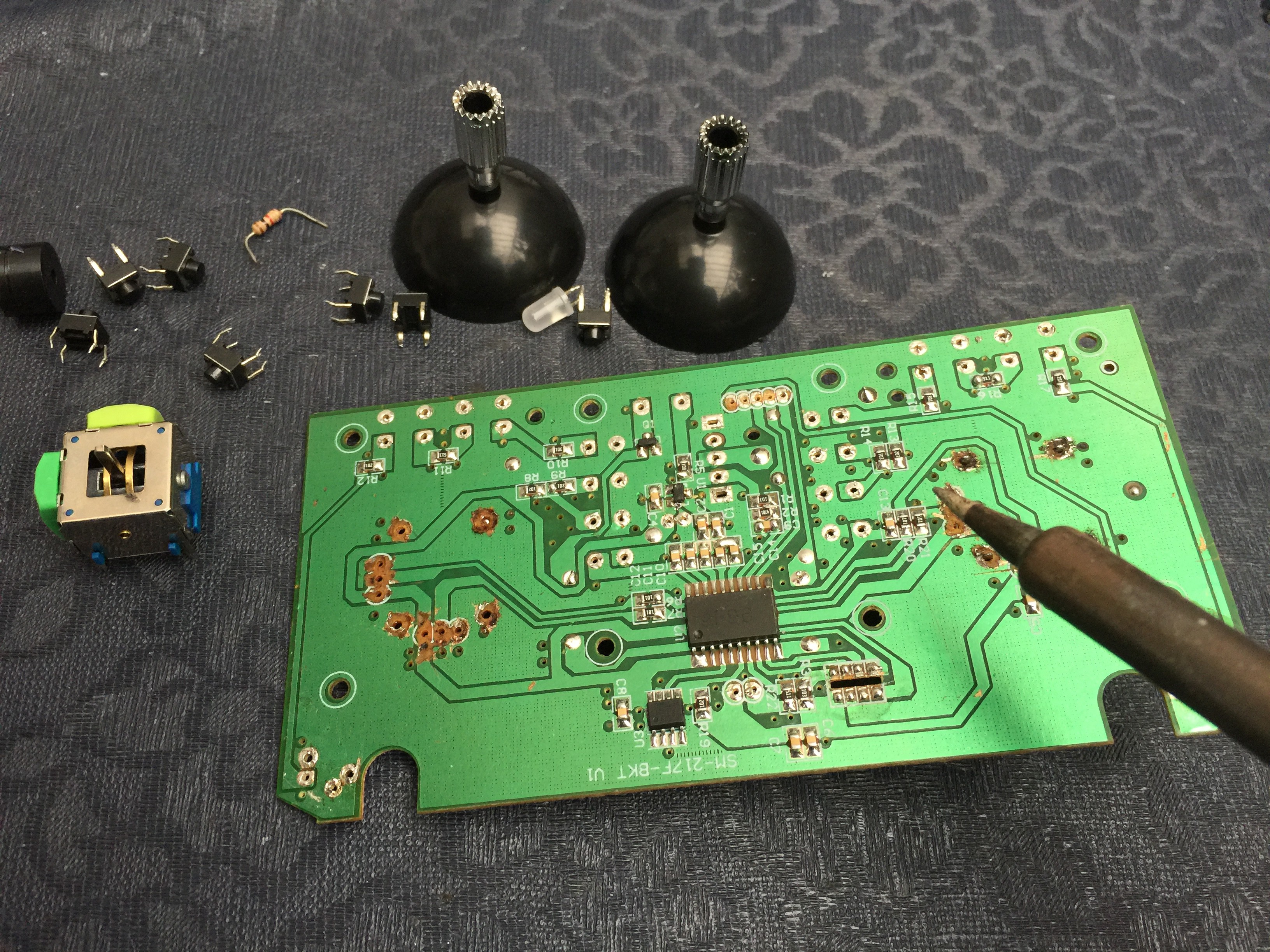
2Step 2
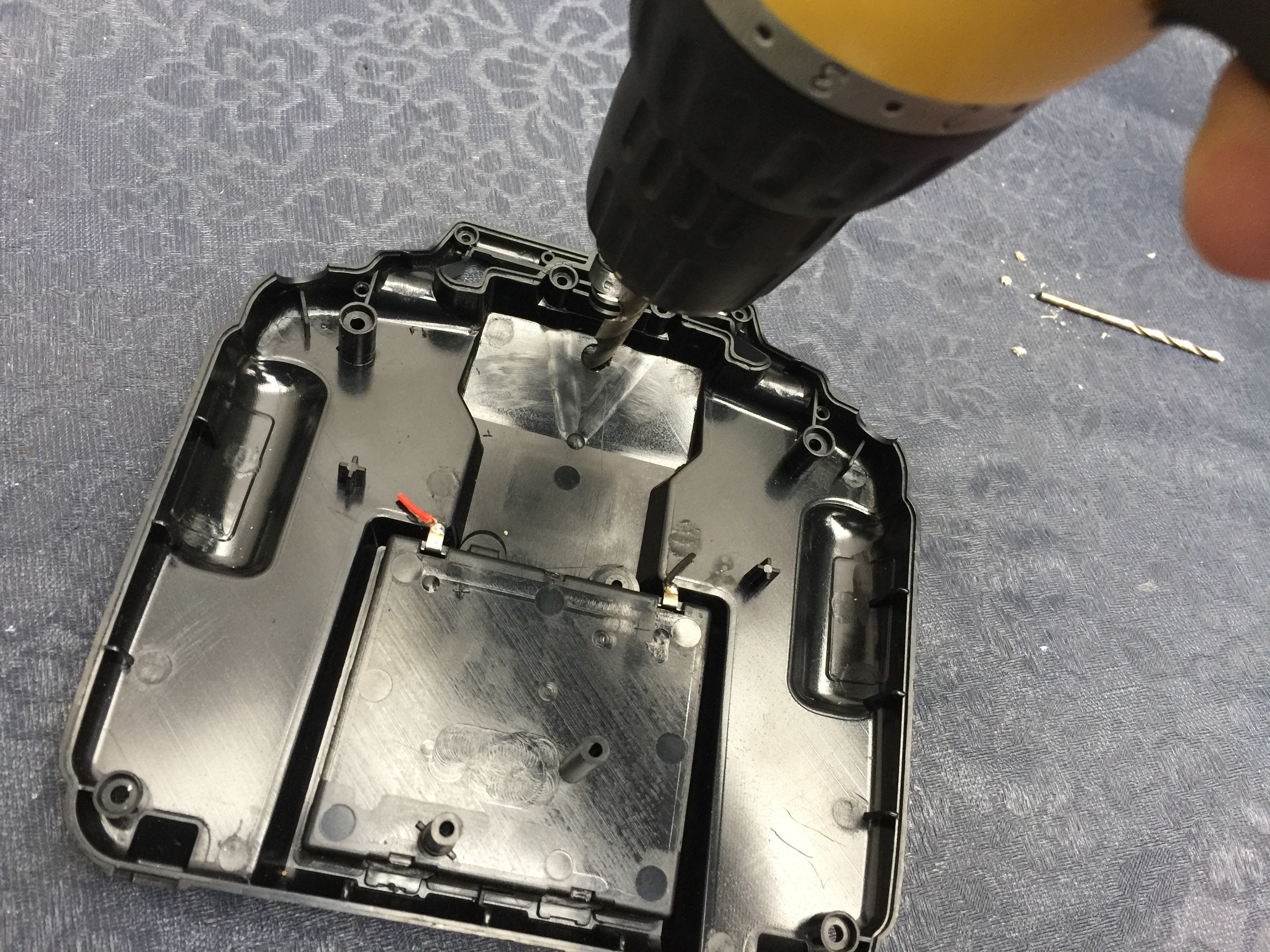
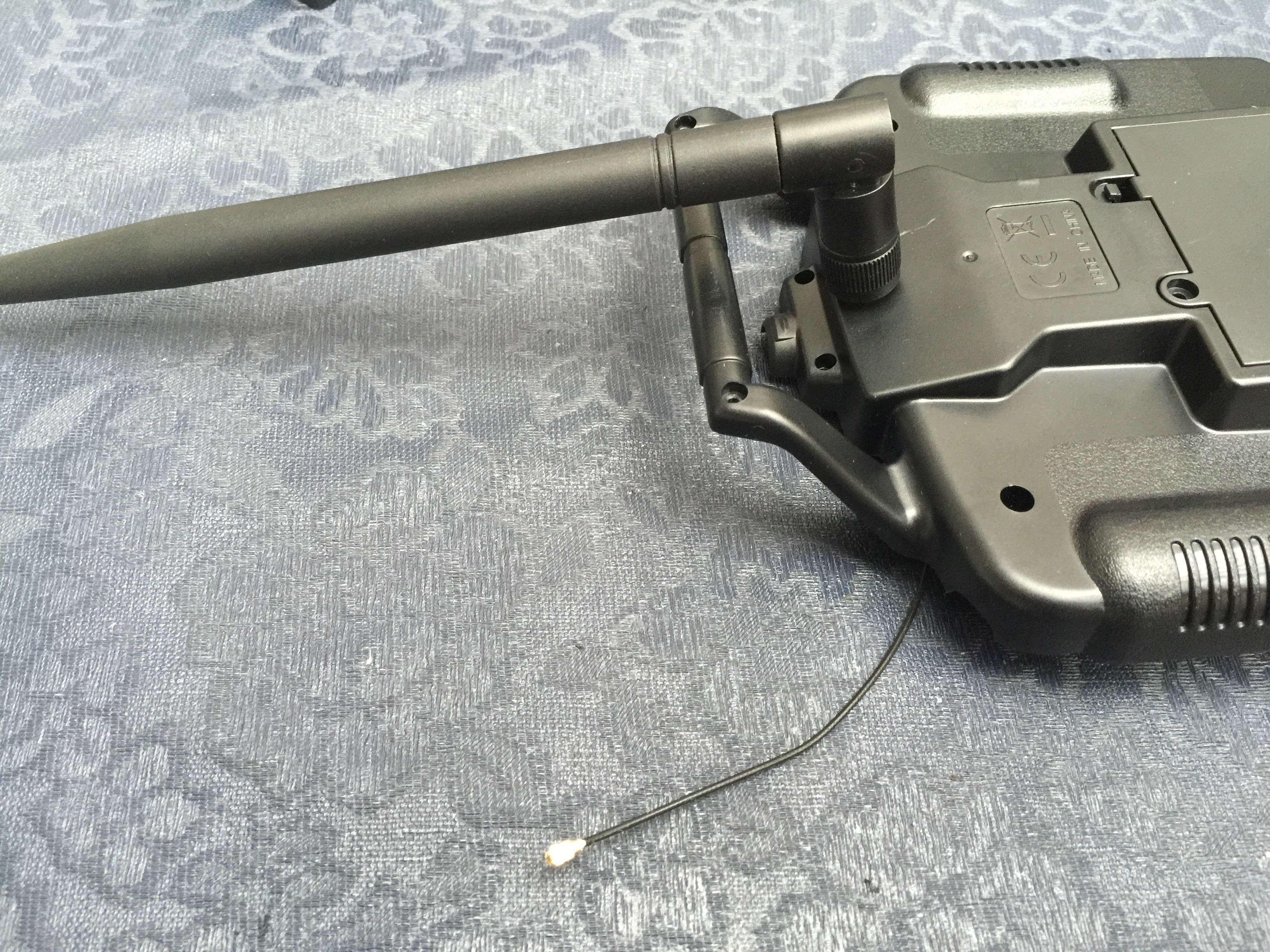
Although the drone will be autonomous, according to the FAA, you have to be able to take control over your drone at any time. Thereby, I ordered a Syma controller from Aliexpress. Then, I harvested all the components, enclosure, sticks and screws. I am planning to add a Xbee module, so that I drilled a hole on the enclosure for the SMA connector.
![]()
![]()
The plan is to design a new controller PCB with custom and original parts. This new PCB should have the same shape.
![]()
-
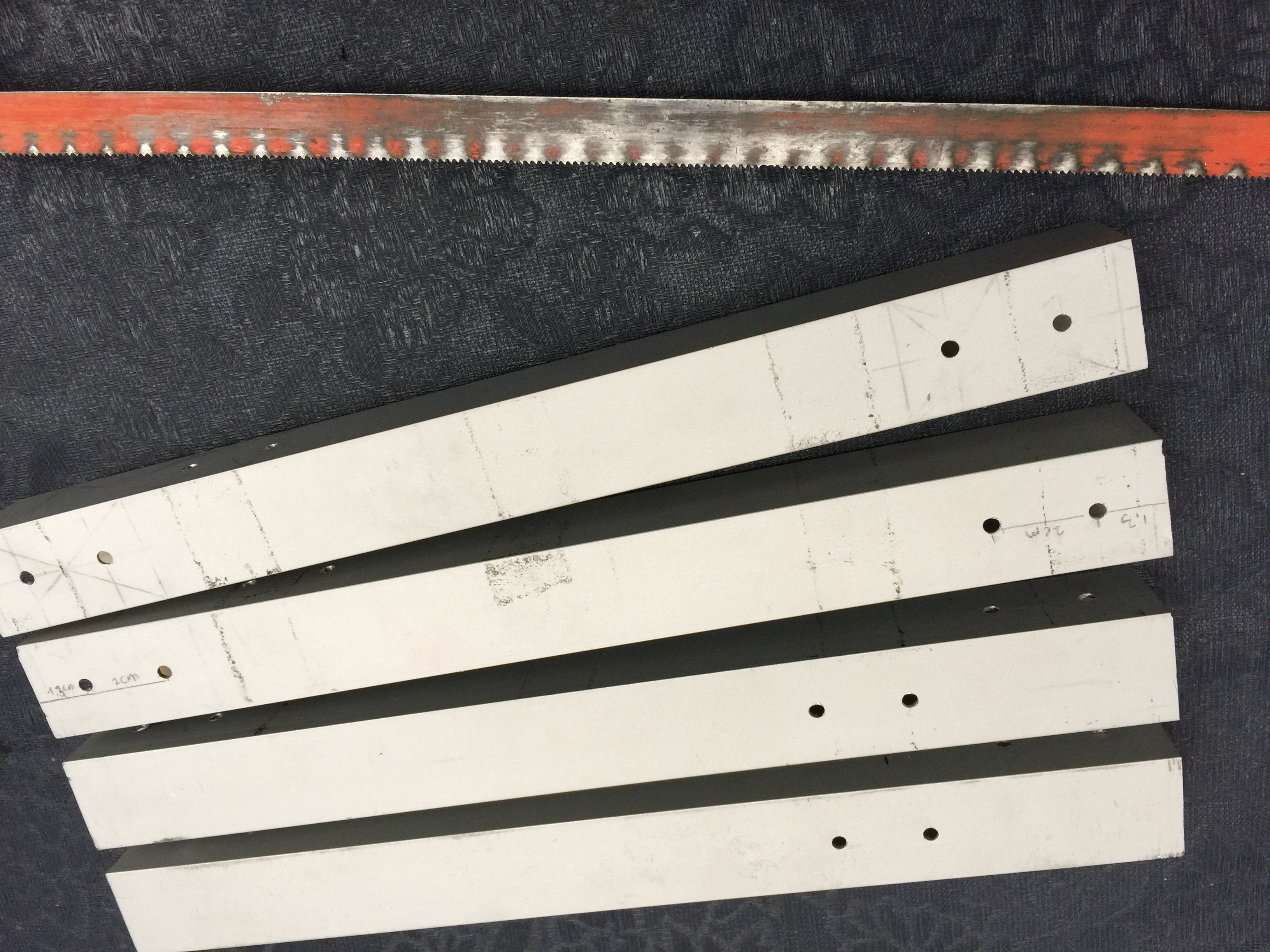
3Step 3
In order to attach the brushless motors to the center parts, I cut four pieces from a square aluminum tube. My tools are limited, but I got it. Also, I drilled 12 holes on every piece. See dimensions in the DWG file (GitHub) and BOM section.
![]()
-
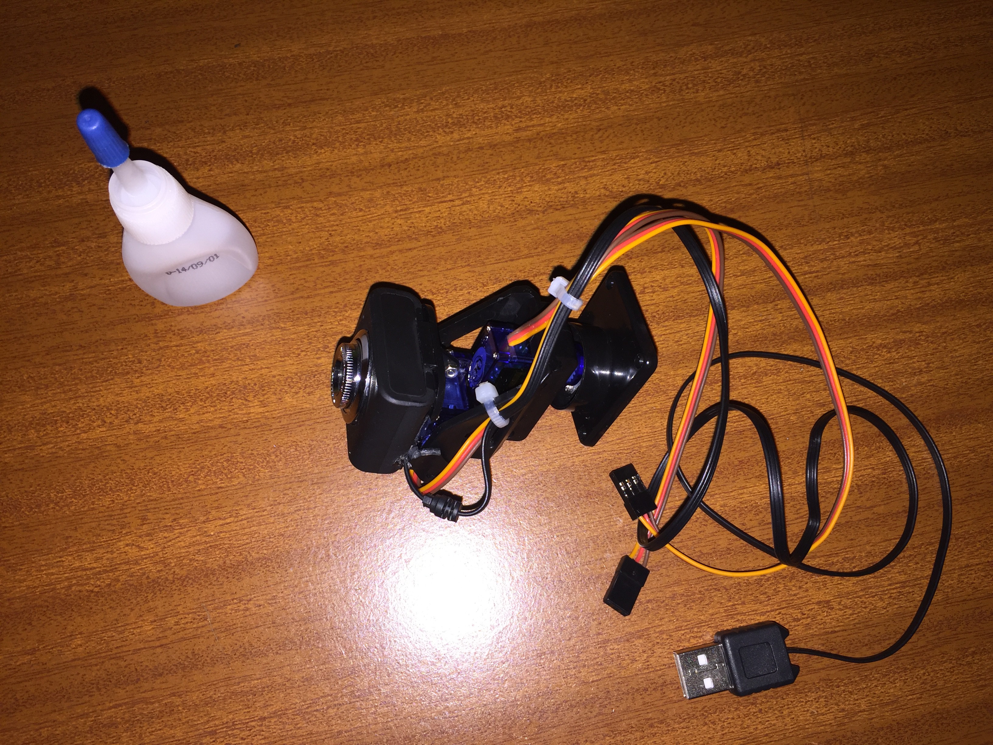
4Step 4
I glued a cheap USB camera to a cheap base with 2 servos.
![]()
Fiva Drone: Automatic Landing/Charging Quadcopter
Fully Automatic Open Source Quadcopter and Landing/Charging Platform, made from scratch.
Discussions
Become a Hackaday.io Member
Create an account to leave a comment. Already have an account? Log In.