-
Field Test: La Brea Tar Pits - February 3rd, 2018
02/28/2018 at 08:04 • 0 comments![]()
![]()
I've been working towards this one for a bit now.
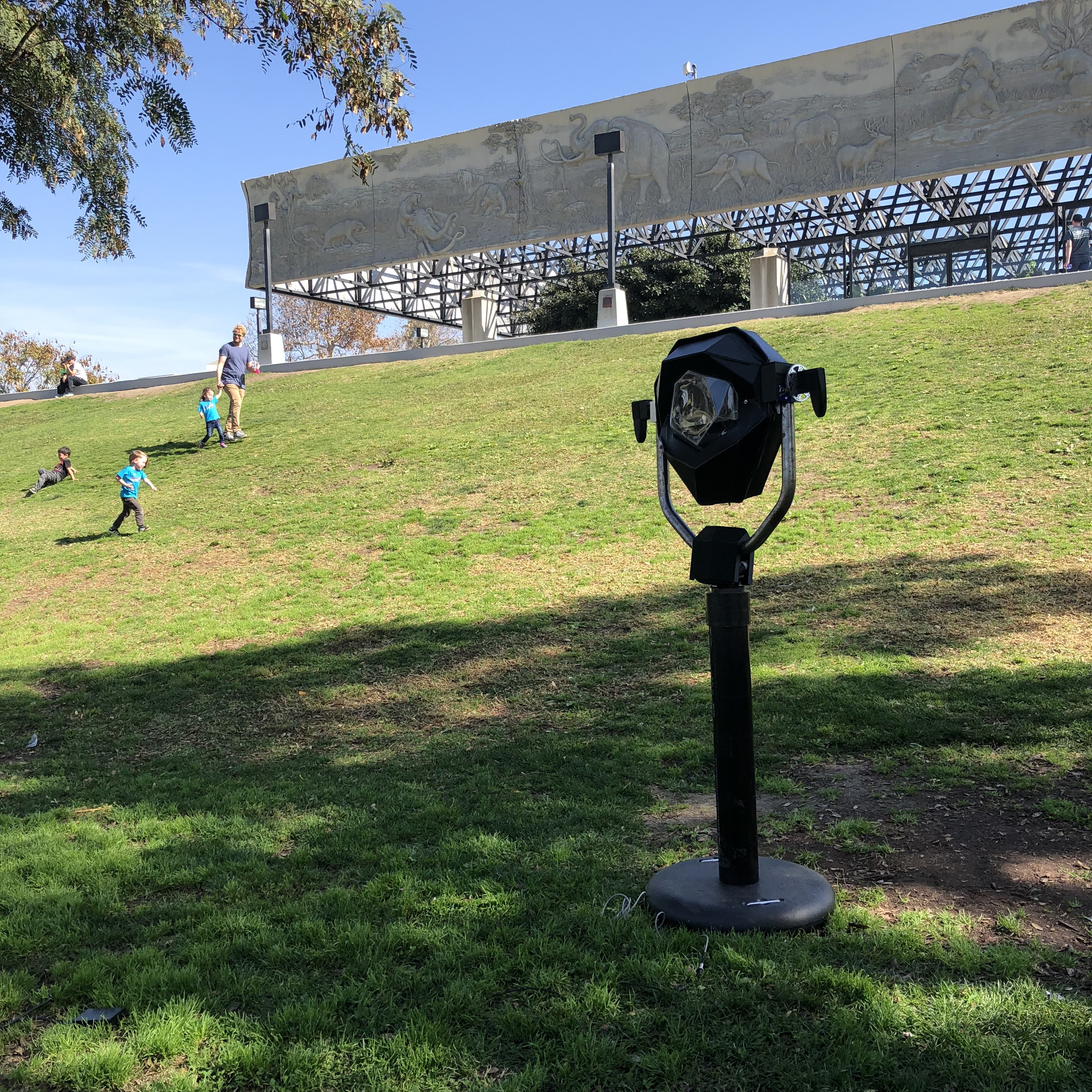
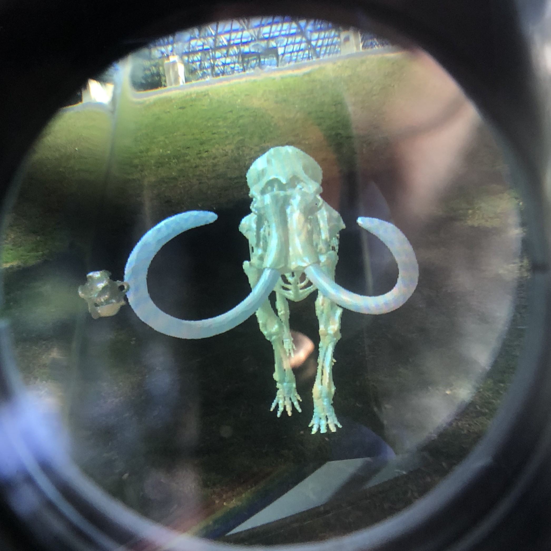
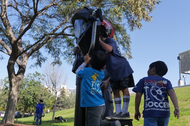
We set it up a picnic for the afternoon under a shady tree. The experience I had designed was rudimentary, but felt like a simple expression of the space. A mash-up of photogrammetry scans of mammoths, sabertooth, and bison fossils stood in front of you. Looking behind were historical panoramas of the Tar Pits in its past.
![]()
![]()
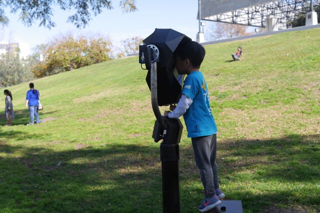
One of the most popular and necessary features was the electric shutter, allowing you to dim in or out the outside world. It's essentially a fader between AR and VR experiences.
Overall it was a successful voyage into an everyday public space and I'm excited to be exploring the possibilities of this place in particular as the year progresses.
-
Field Test: DTLA Mini Maker Faire
02/28/2018 at 07:17 • 0 commentsThings are slowly taking shape. These past few months I've been able to get this prototype into the field in front of people. Nothing especially permanent yet, but it's taking bruises now and getting more refined.
DTLA Mini Maker Faire - Dec 2 2017
What better way to start than a Maker Faire.
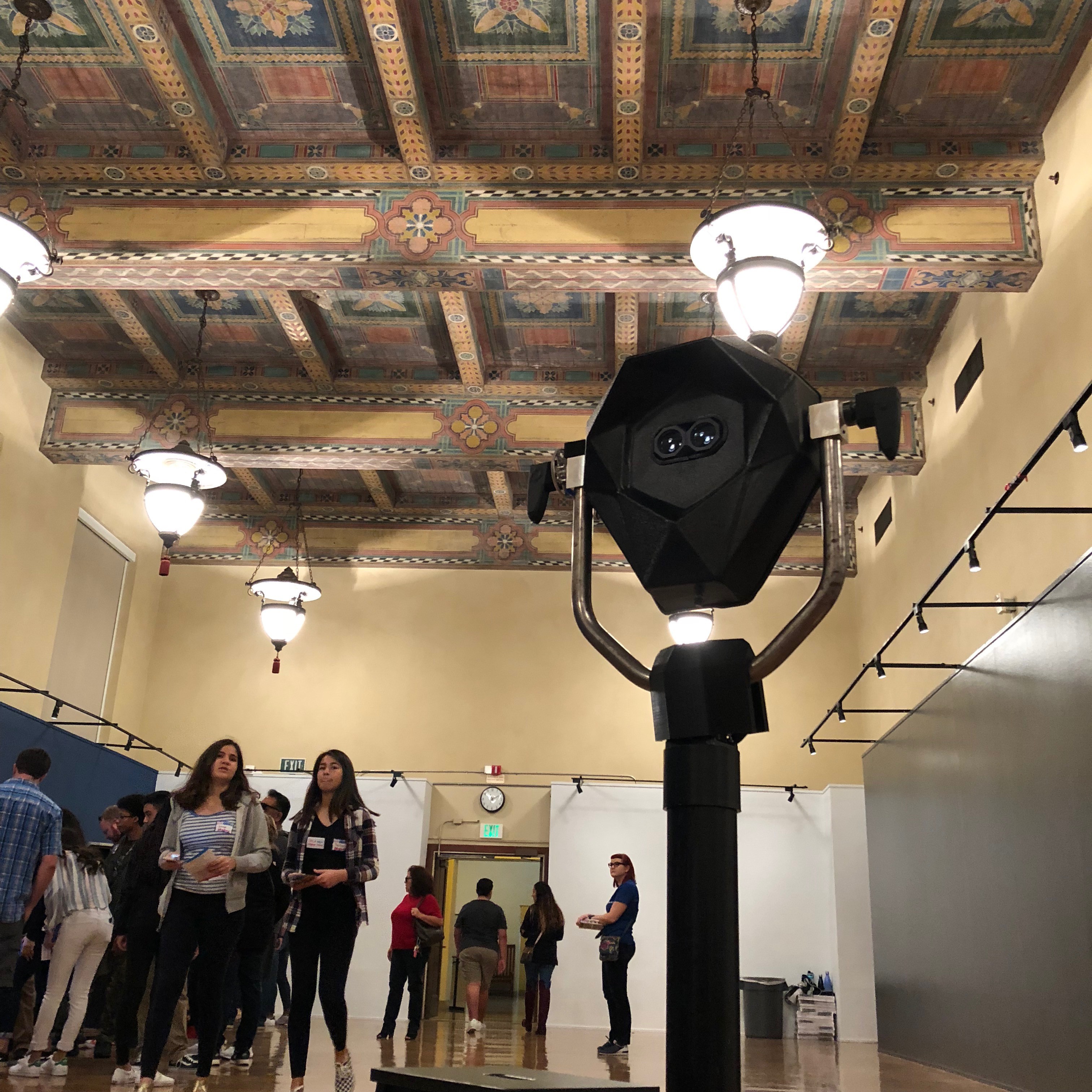
The Los Angeles Central Public Library is beautiful, and just being able start there felt like an honor. Maker Faires are great places to test precisely because of the ethos of everyone there. It's about sharing the how even more than the what.
![]()
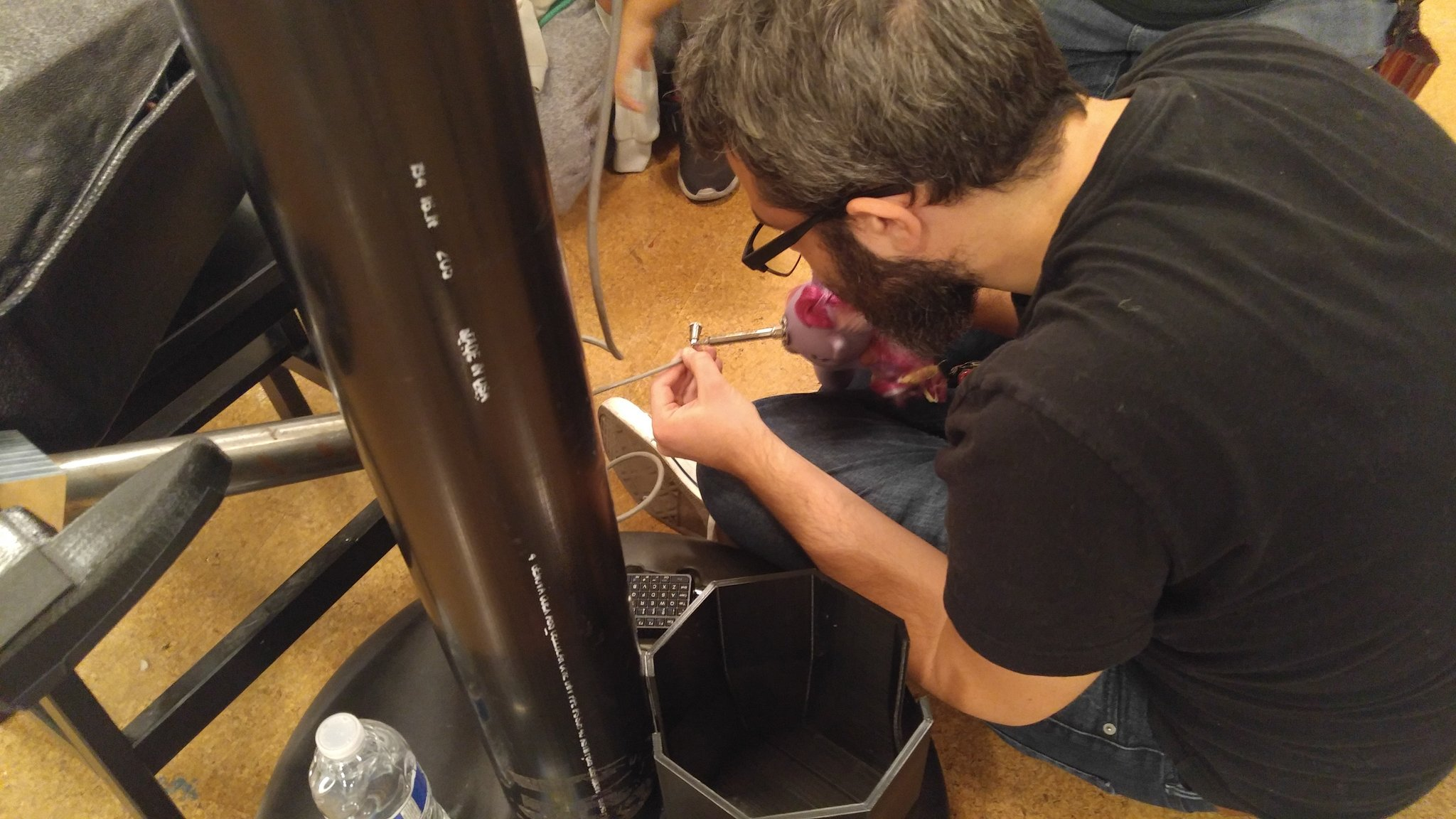
If something breaks down, it's a teaching moment, not a mistake. In particular, I rushed building my power cables the night before, and found myself demonstrating soldering techniques with Sparkles, the Crash Space mascot soldering iron.
At DTLA @makerfaire, @perceptoscope being fixed by Ben with the help of Sparkles. pic.twitter.com/llpZinRZg9
— Kevin Jordan (@idreamincode) December 2, 2017It gave me a sense of the logistics, from setup to breakdown, and I learned a lot about where I could refine the design and interface.
![]()
Experientially, I had been demonstrating some WebVR and A-Frame scenes, playing around with photogrammetry scans of artifacts and letting users activate them to get other views. It would help inform what was to come next.
-
Production Horizon
11/11/2017 at 08:46 • 0 commentsAfter a long and exhausting journey of systems integration, testing, and coding, we're ready to put the latest prototypes out into the world and gear up for production early next year. Lots of exciting locations and partnerships are in the works that I'll be sure to update on as the final details come together. Since August, I've also been deep diving into the organizational sustainability and community aspects of the project as a National Arts Strategies Creative Community Fellow.
In the immediate future, I'm excited to announce you'll be able to experience the latest Perceptoscope in person at the DTLA Mini Maker Faire on Saturday December 2nd. It should be a lot of fun to share what we've been up to with the Maker scene here in LA.
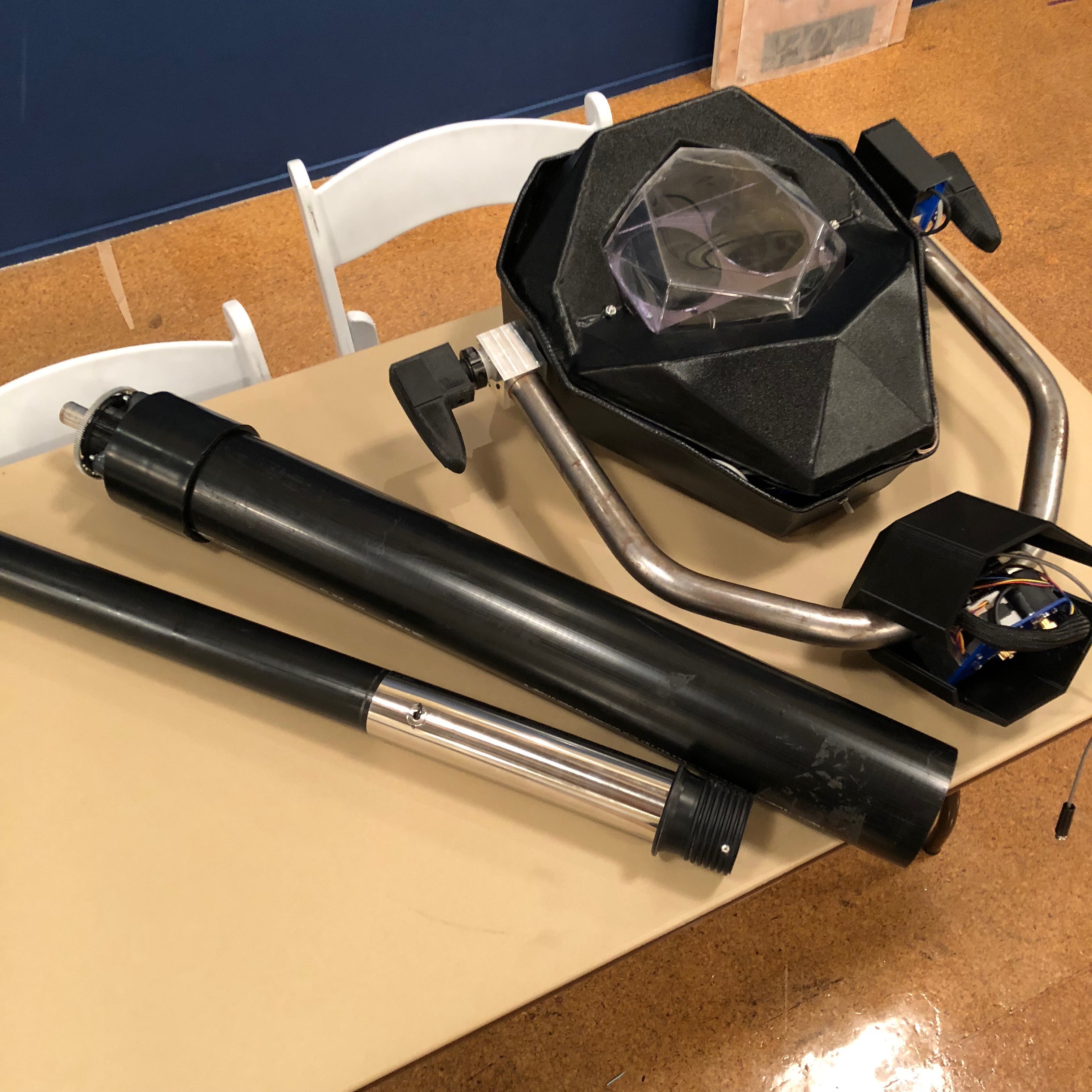
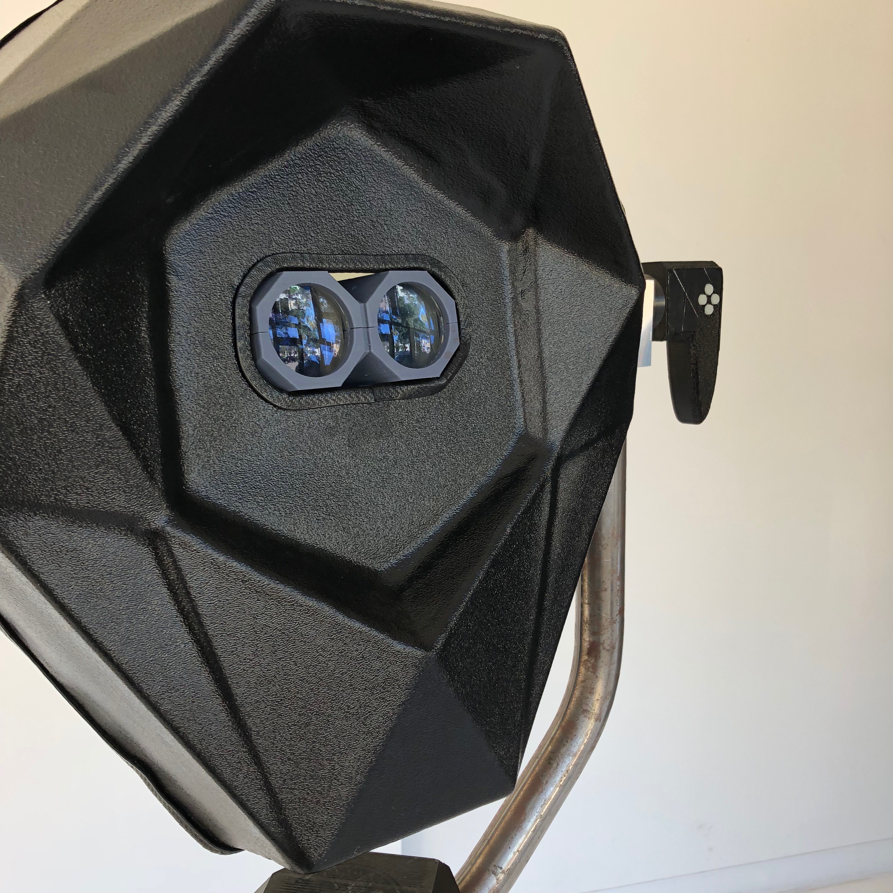
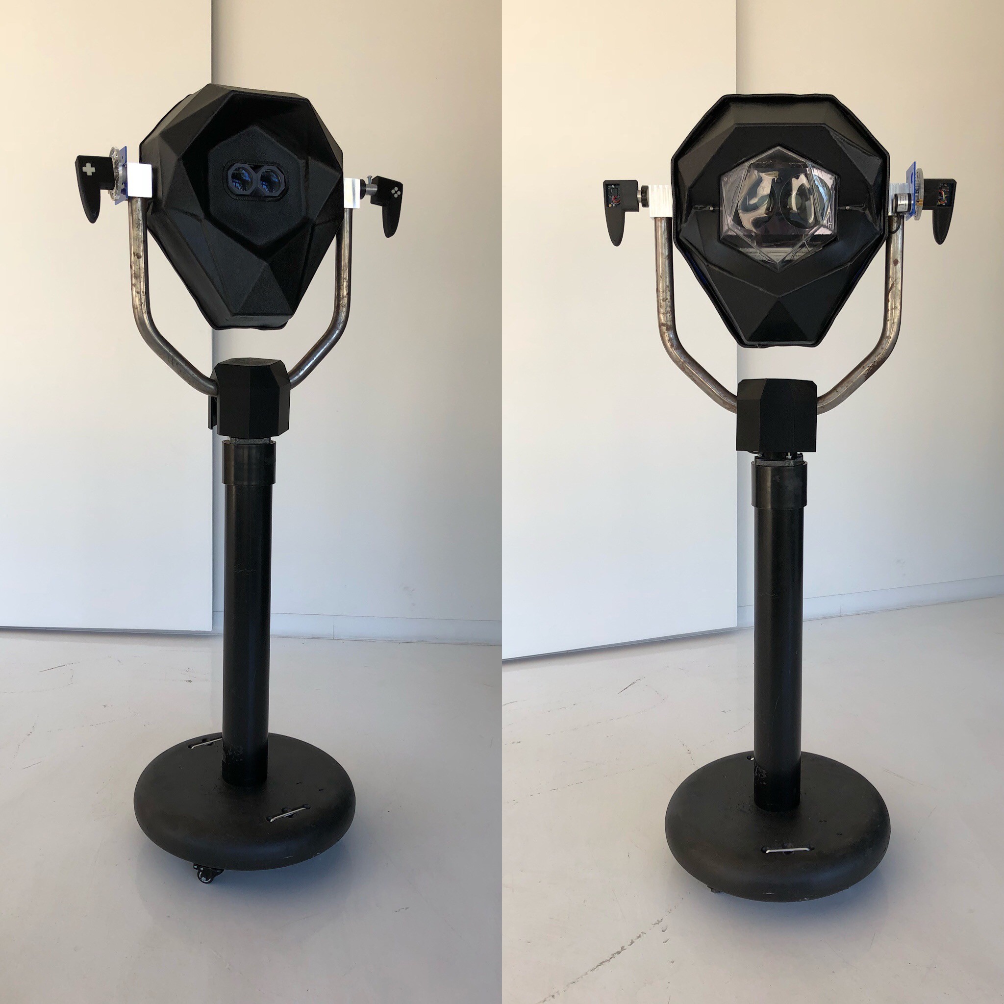
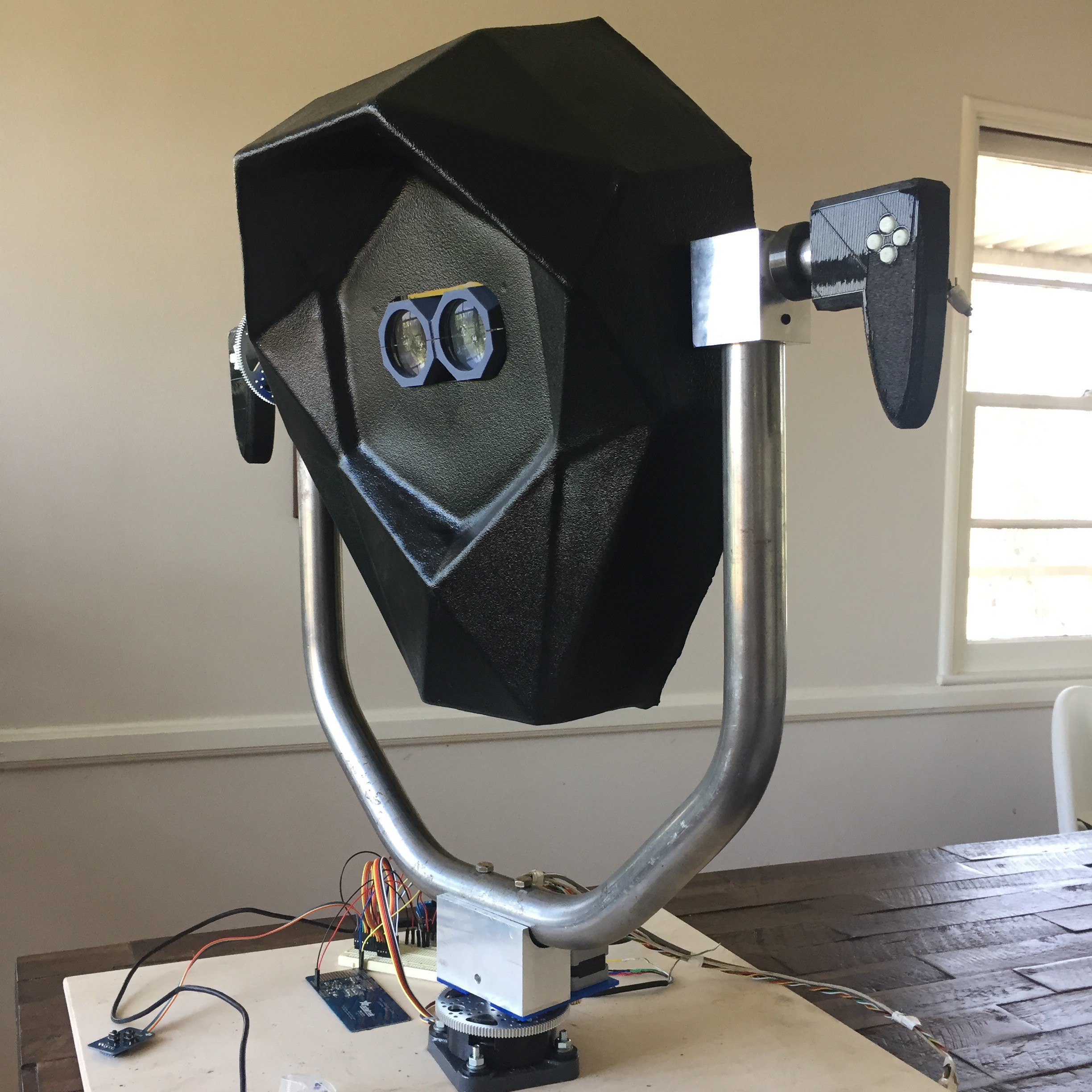
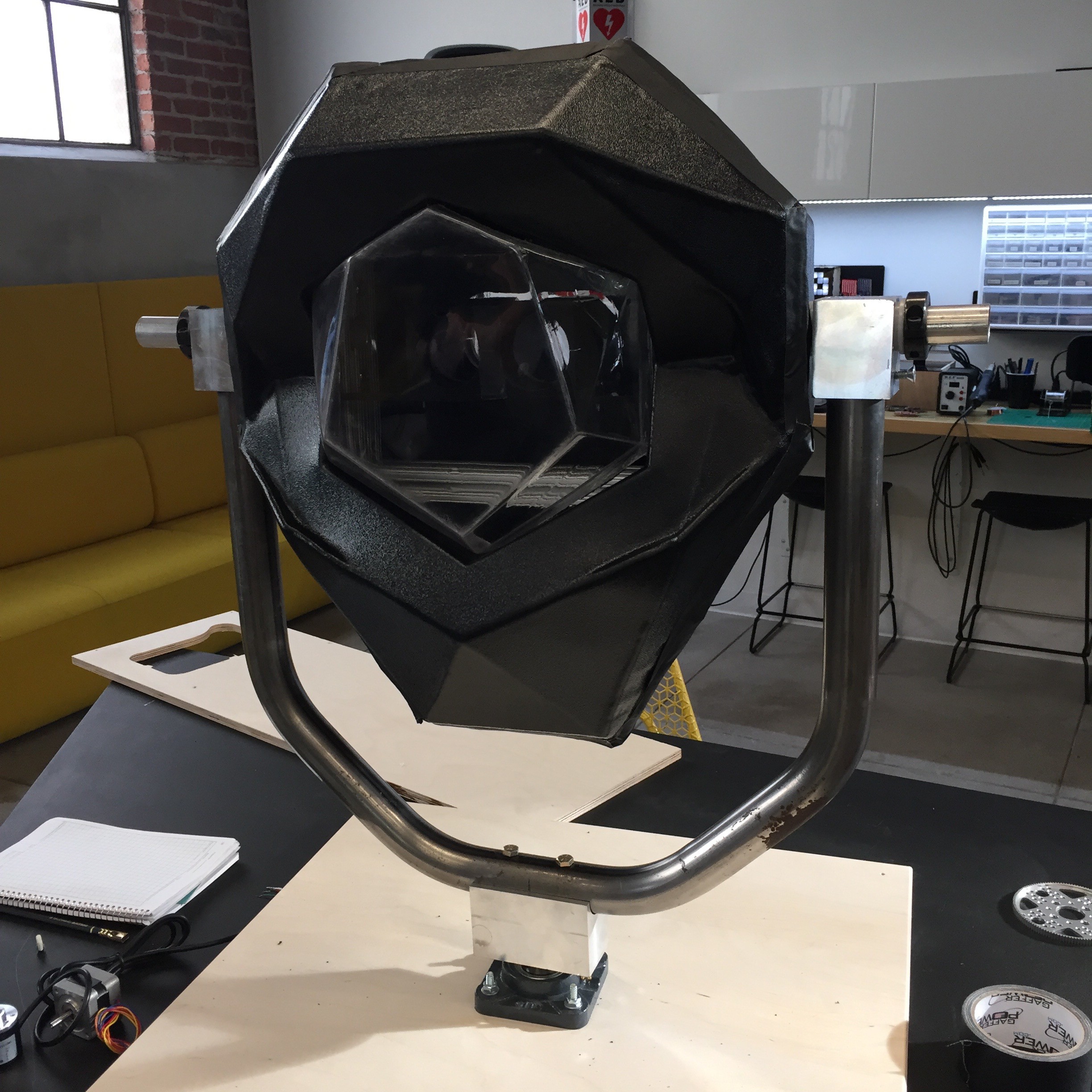
And now for a quick tour of the final pre-production prototype...
![]()
![]()
Special thanks to Dan and the rest of the gang at the Design Lab for helping me with this final push on fabrication.
---------- more ----------
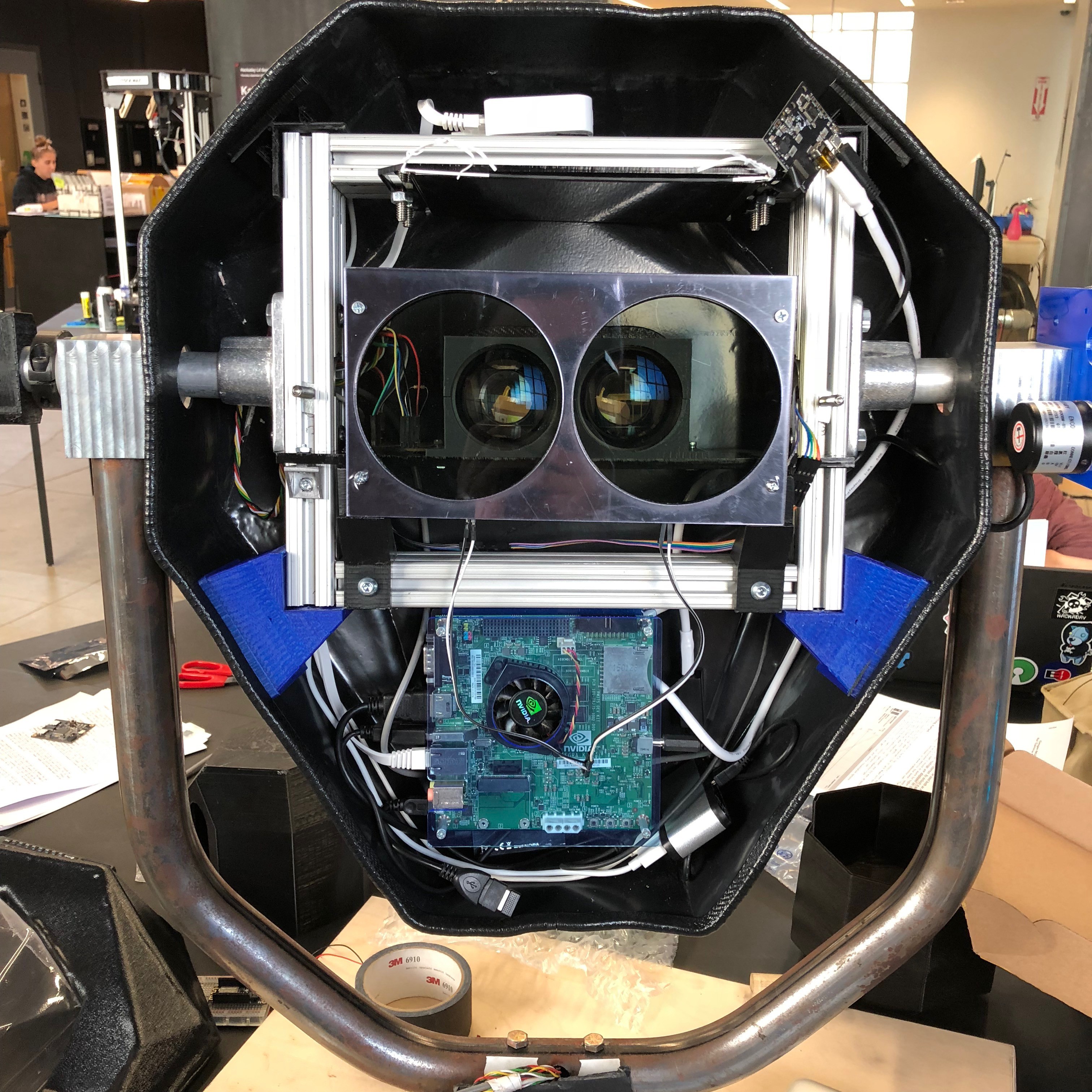
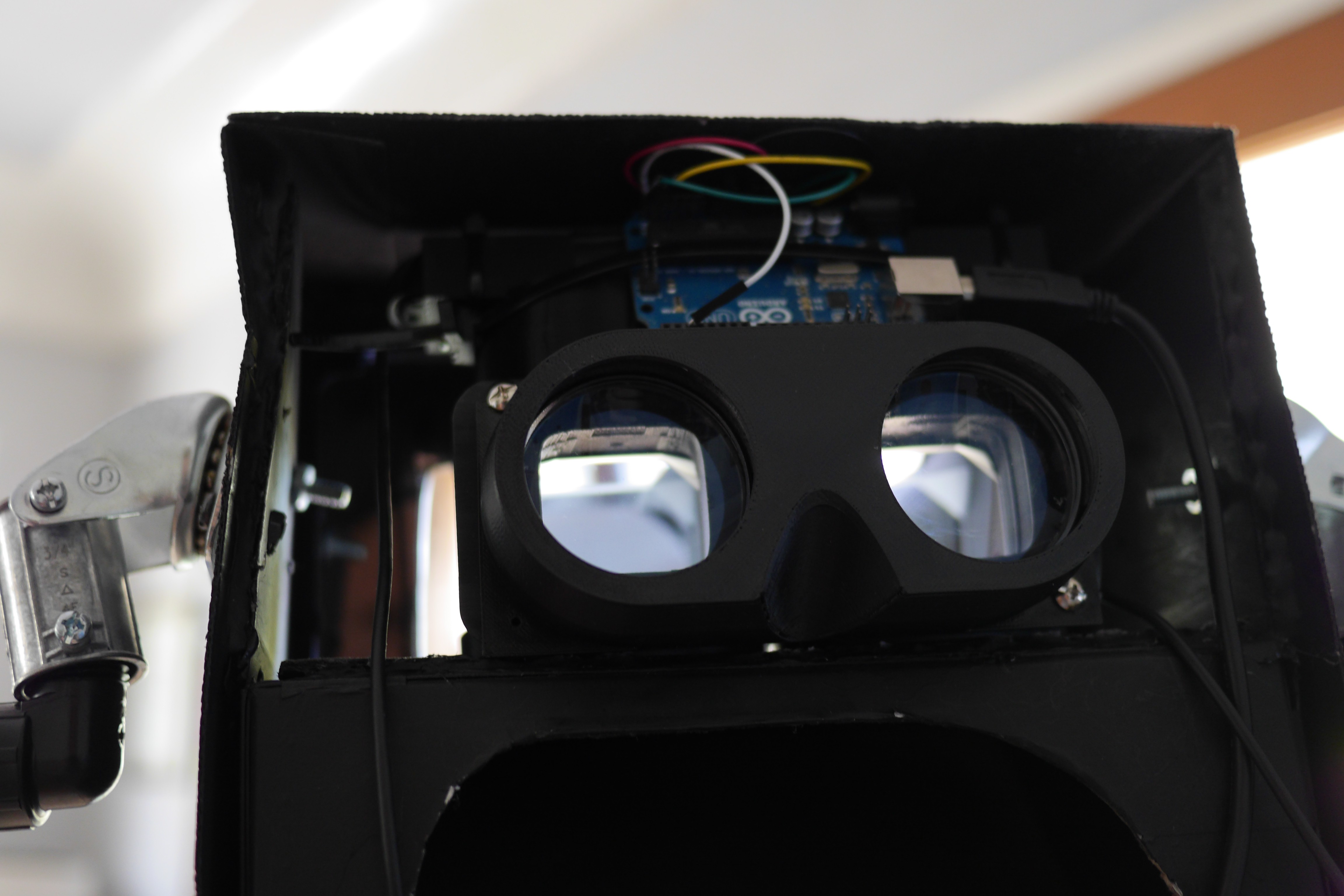
On the systems front, the big changes to note are we've bumped up to high dpi 2k resolution display which proved to be surprisingly challenging based on our original combination of components. After some experimenting are now using the NVIDIA Tegra Platform to power the project. We can easily deploy on both ARM or x86 systems now, and so it really will come down to what makes the most sense for a given deployment in terms of power consumption and cost.
The Tegra TK1 is a beast of an ARM system, and I've been really impressed by the graphics performance for such a relatively inexpensive board. Moving up to the TX1 or TX2 could open up an even more impressive array of possibilities as we integrate additional computer vision and machine learning algorithms into the platform.
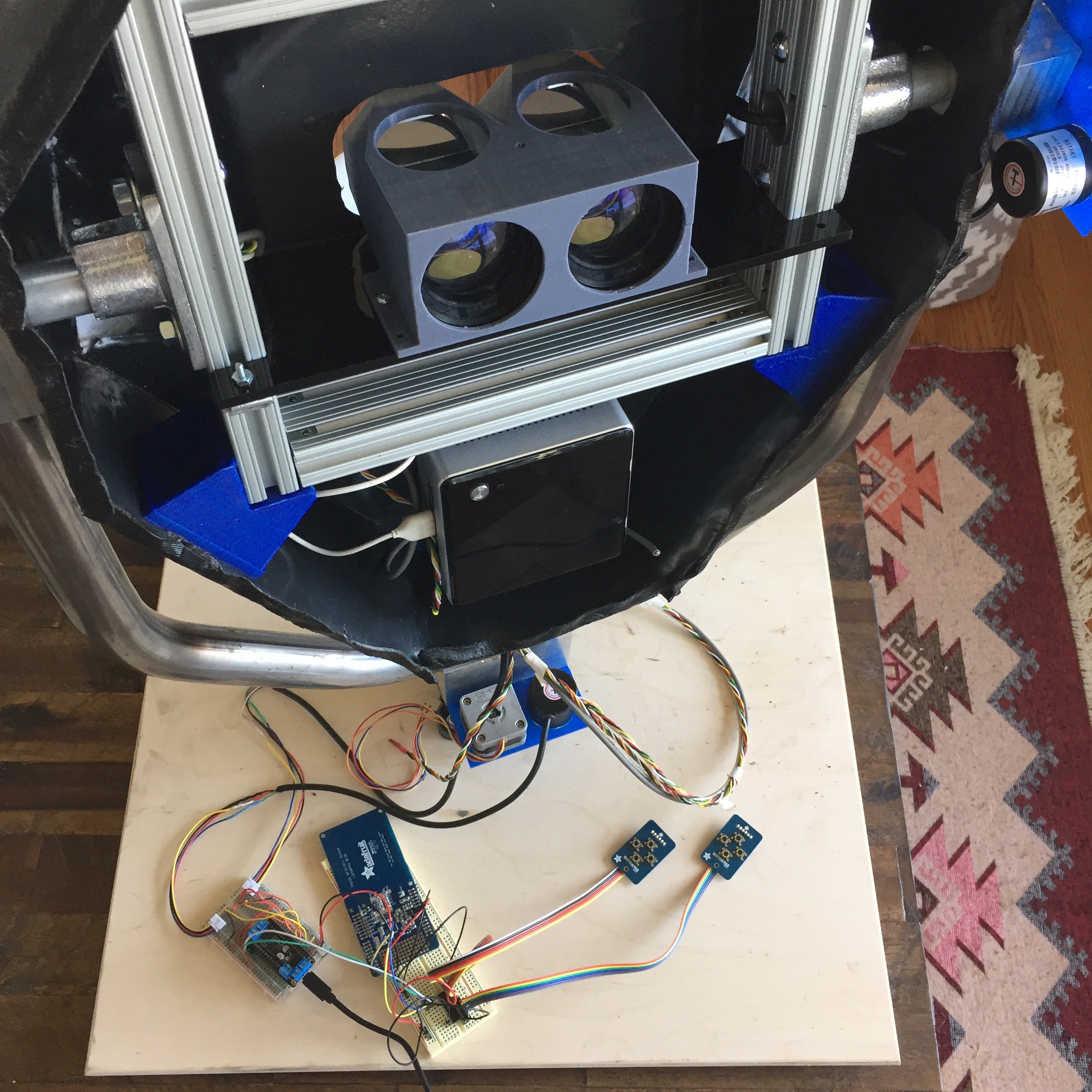
Also worth noting is the electronic shutter that now gives easily variable control of the light entering the optics. Up until now I had been manually adjusting variable ND filters in front of each eye depending on ambient lighting conditions, which was both tedious and unsustainable in a permanent deployment. Currently a simple circuit controls the shutter with a potentiometer at the bottom of the viewer, but the idea will be to use an additional light sensor to dynamically adjust the shutter as necessary.
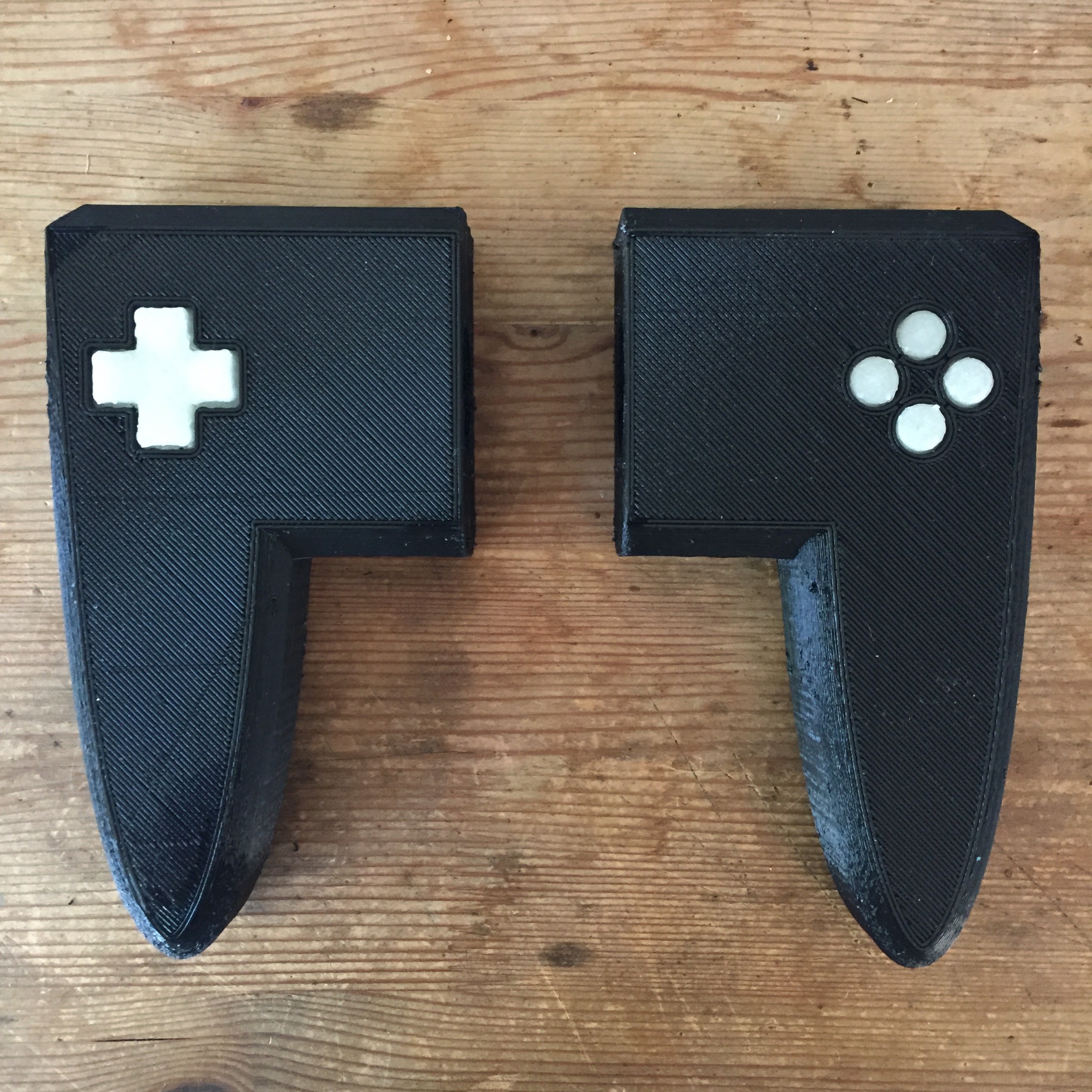
Buttons and DPad on the handles are a combination of Adafruit PiGrrl Zero boards with a MCP23008 port expander -- the idea is to use easily accessible off the shelf components throughout the system so we can scale up quickly.
![]()
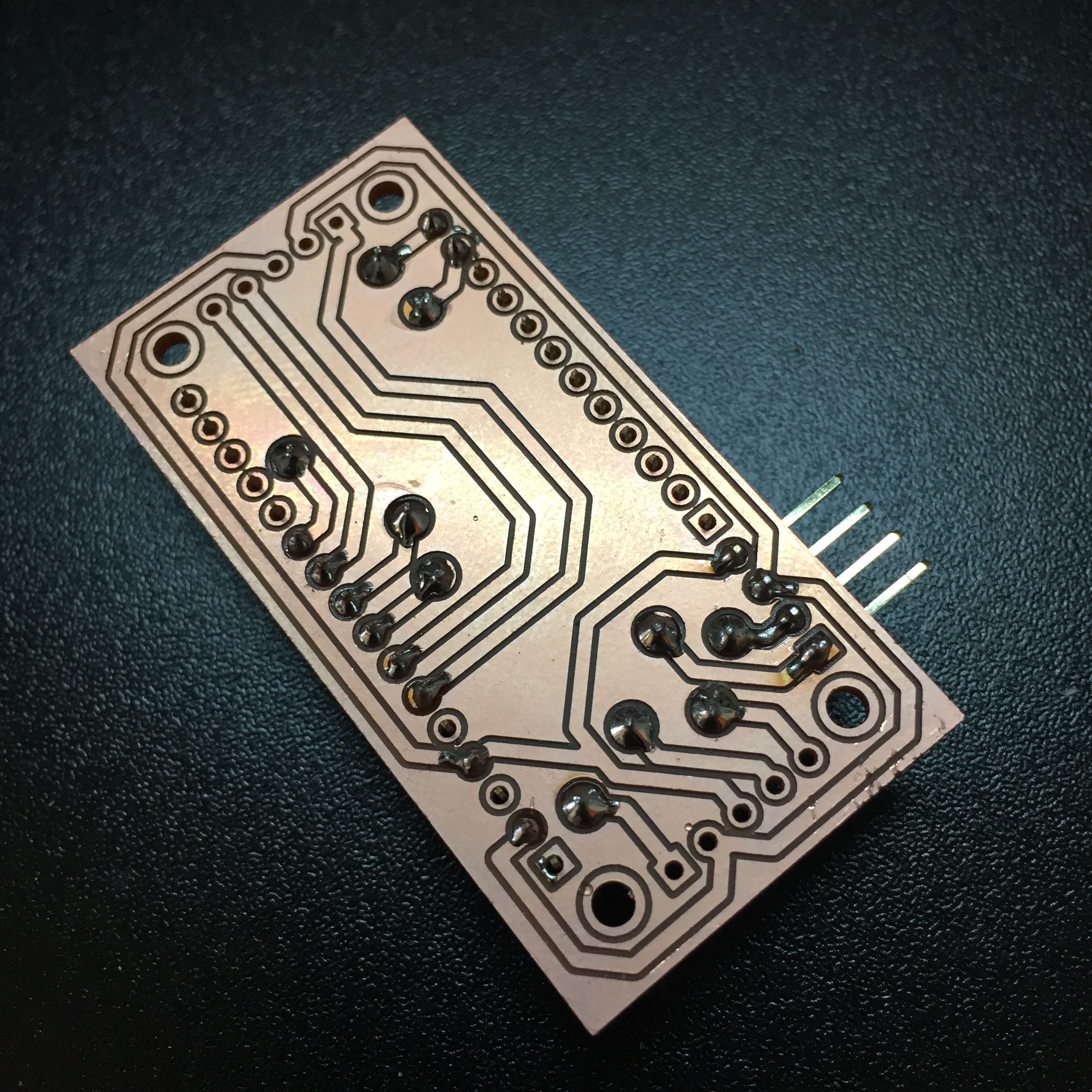
I finally had a chance to design some boards on the Othermill, and felt really empowered by the process. This is a breakout board I designed to interface all of the sensors throughout the Scope with the AdaFruit feather form factor we adopted for the microcontroller. Going with the feather system has made it super straightforward to add things like motorcontrollers or small status displays. Eventually we'll design our own custom boards top to bottom, but working with preexisting components will let us move much more quickly.
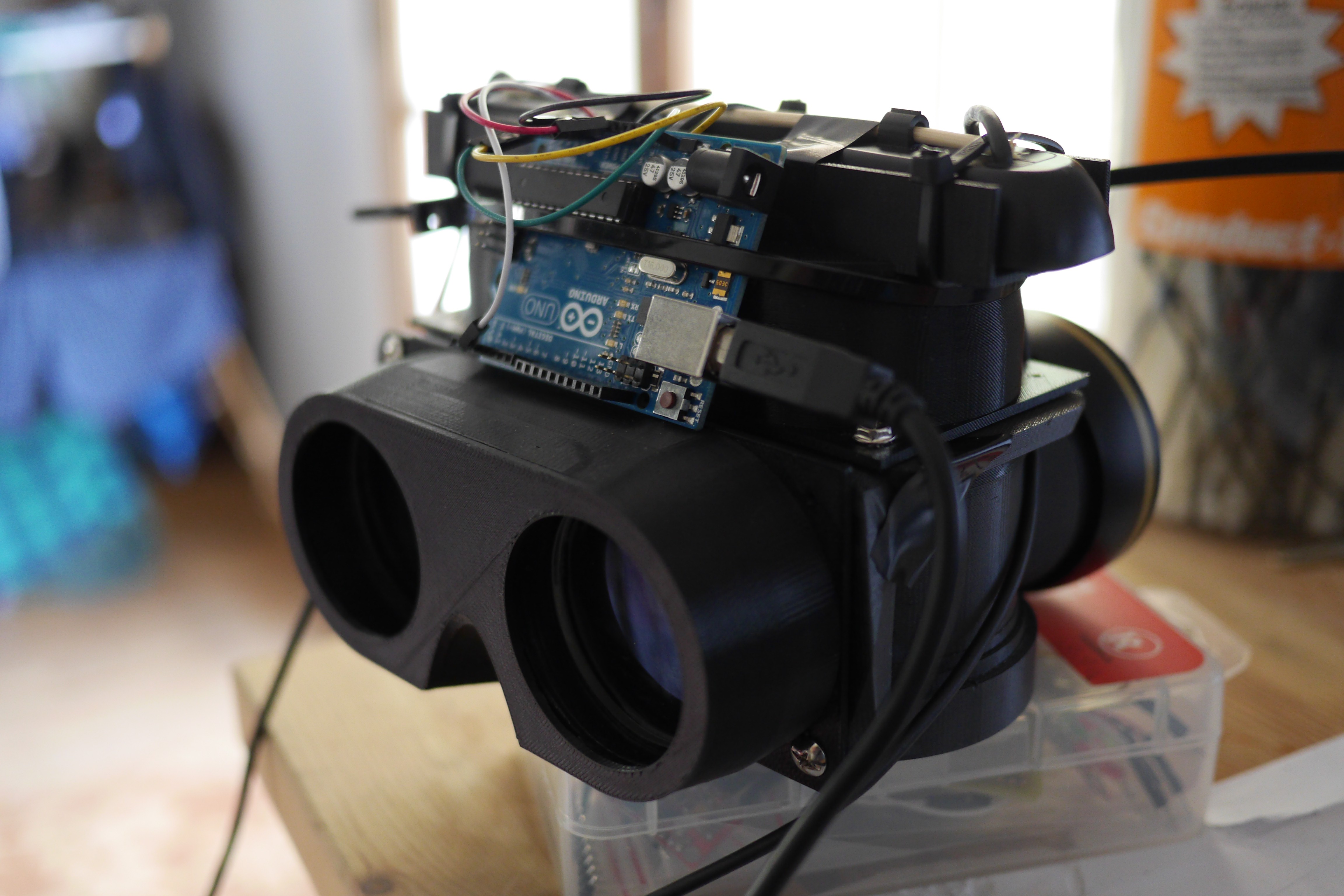
We wanted a microcontroller with great performance and a lot of interrupt pins to get the best resolution we can out of the optical rotary encoders, and went with the much loved PRJC Teensy 3.2 in a feather adapter. So far we've been really happy with both the latency and rotational resolution we're achieving with the whole system.
It's a strange feeling to look back at how far the project has come since it was just a bunch of taped up cardboard in my apartment. Even with all the work that's gone in so far, it really feels like I'm just now getting started on doing the work I set out to do.
-
Integrating Systems and Activating Networks
05/04/2017 at 21:14 • 0 commentsTowards the end of my time as a resident at the DesignLab last fall, I had the opportunity to become an Activate Cultural Policy Fellow through Arts for LA, a regional non-profit focused on advocating for issues around arts access and education around LA county. Now with this fellowship soon coming to an end, I thought it would be good to reflect on what came about through this process, as well as put it into the greater context of where Perceptoscope is going next.
But first a quick update on the build itself. Much of the latest effort has been this final push of systems integration: tricking out our prototypes with all of the sensors, microcontrollers, computers and wiring they would need to become functional interactive installations.
Our 3D printer has been running non-stop, building out custom mounting brackets, gamepad handles, and other assorted knicknacks. Lasercut acrylic is serving as a stopgap until we can get access to a waterjet or plasma cutter. We're trying to iterate and test designs quickly and efficiently.
It can be a messy process but we've gotten better and better at it each time. They'll be a larger update soon with the final results of this build and what we've learned along the way. Each step, whether technological or organizational, has brought momentum to the project and hope for what comes next.![]()
![]() The Activate Fellowship was focused on the hyperlocal. Fellows are based in their city council district, and expected to build an action plan to implement with local leaders on the ground. We went through monthly leadership and advocacy training, got to explore a variety of influential community arts organizations, and were given introductions to important civic decision makers that could link us to opportunities or collaborators.
The Activate Fellowship was focused on the hyperlocal. Fellows are based in their city council district, and expected to build an action plan to implement with local leaders on the ground. We went through monthly leadership and advocacy training, got to explore a variety of influential community arts organizations, and were given introductions to important civic decision makers that could link us to opportunities or collaborators.For Perceptoscope, this process has been immensely helpful. Though much of this project is technological, its ability to grow as a public arts initiative is tied more deeply to issues around public arts policy, street furniture permitting, and creative placemaking initiatives. Building the right organizational foundation and finding our fit in the larger ecosystem of arts and public media is critical to the future success of the project.
Being fully thrown into this community of arts and arts advocacy also led to exciting opportunities outside of the fellowship that I otherwise would not have known about. I went to an incredibly helpful Arts Tune Up run by the LA County Arts Commission, played with open data portals as part of a team at LA's first ever Arts Datathon, and had a meeting with my council office at City Hall to advocate for community arts as a delegate on ArtsDay.
Along the way, I've also been connecting more directly to some initiatives happening where I live. An area just a few blocks away was recently awarded a Great Streets grant by the Mayor's office and I've now found a community of local artists all sharing creative ideas for the neighborhood.
My hope is to do some playtesting here in collaboration with the local community and local initiatives. I'm just starting to really learn what's around here, and hopefully Perceptoscope can be a way to share those findings and explore some ideas.
The way we think of innovation tends to be focused on hypergrowth, immediate global impact and the arrival of some amazing next new thing. However, when it comes to actually making something, that's never how it happens. It's usually a process with a whole collection of little steps, lucky accidents, and human interactions that play out over a long period of time. How we define the terms of this process is what determines the eventual shape and ongoing life of what we create.
Perceptoscope is just starting to change from a seed to a sprout, and it feels good to know it's well planted in the right type of soil.
-
Prototypically PreProduction
02/23/2017 at 19:30 • 1 commentGetting to this point has been a long journey, from prototypes built out of cardboard and masking tape, to designing something with intention, strength and manufacturing in mind.
![]()
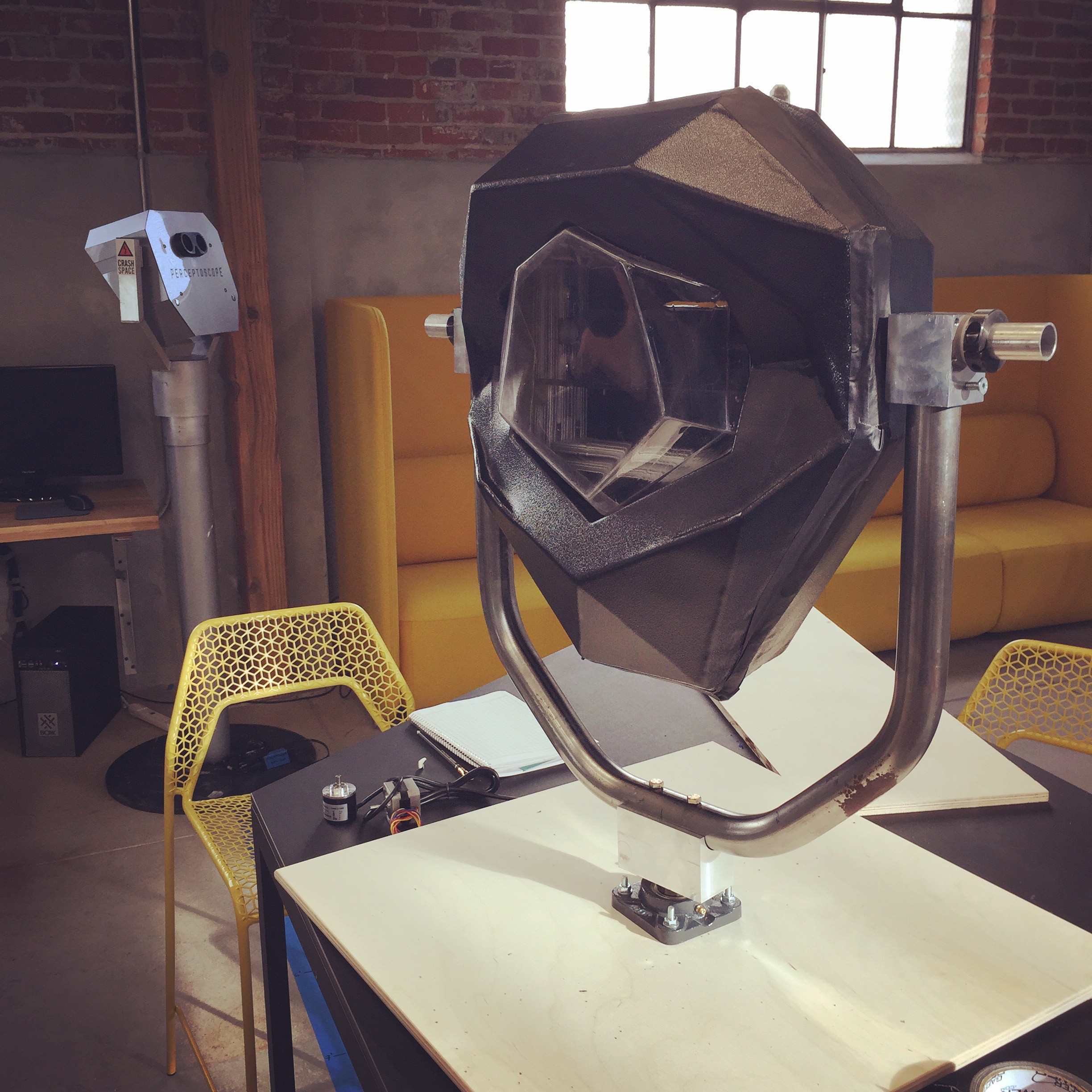
There's still work to be done: integrating the electrical systems, adding a few control components, and fabricating the pedestal, but we're now at a place where making new units is just a matter of repetition.
The challenges in designing and building anything from the ground up are immense. Even an object as simple as a mounting bracket takes time, precision, and imagination. Fortunately we live in a era where the tools are becoming increasingly democratized so that anyone with a little patience and ingenuity and make an idea into something real.
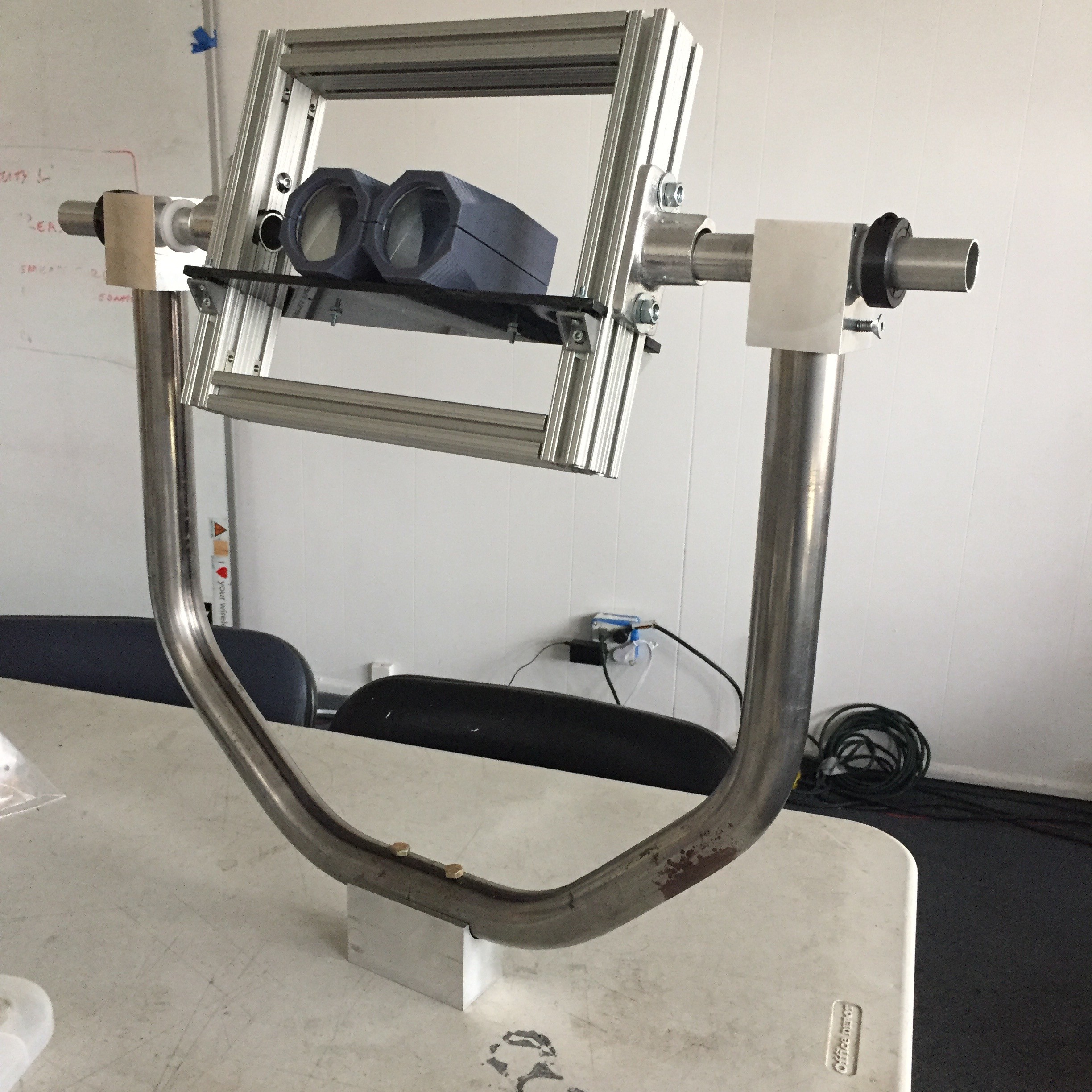
I started final assembly at CRASH Space, threading predrilled holes on the bearing blocks, and laser cutting a shelf to mount the optics.
![]()
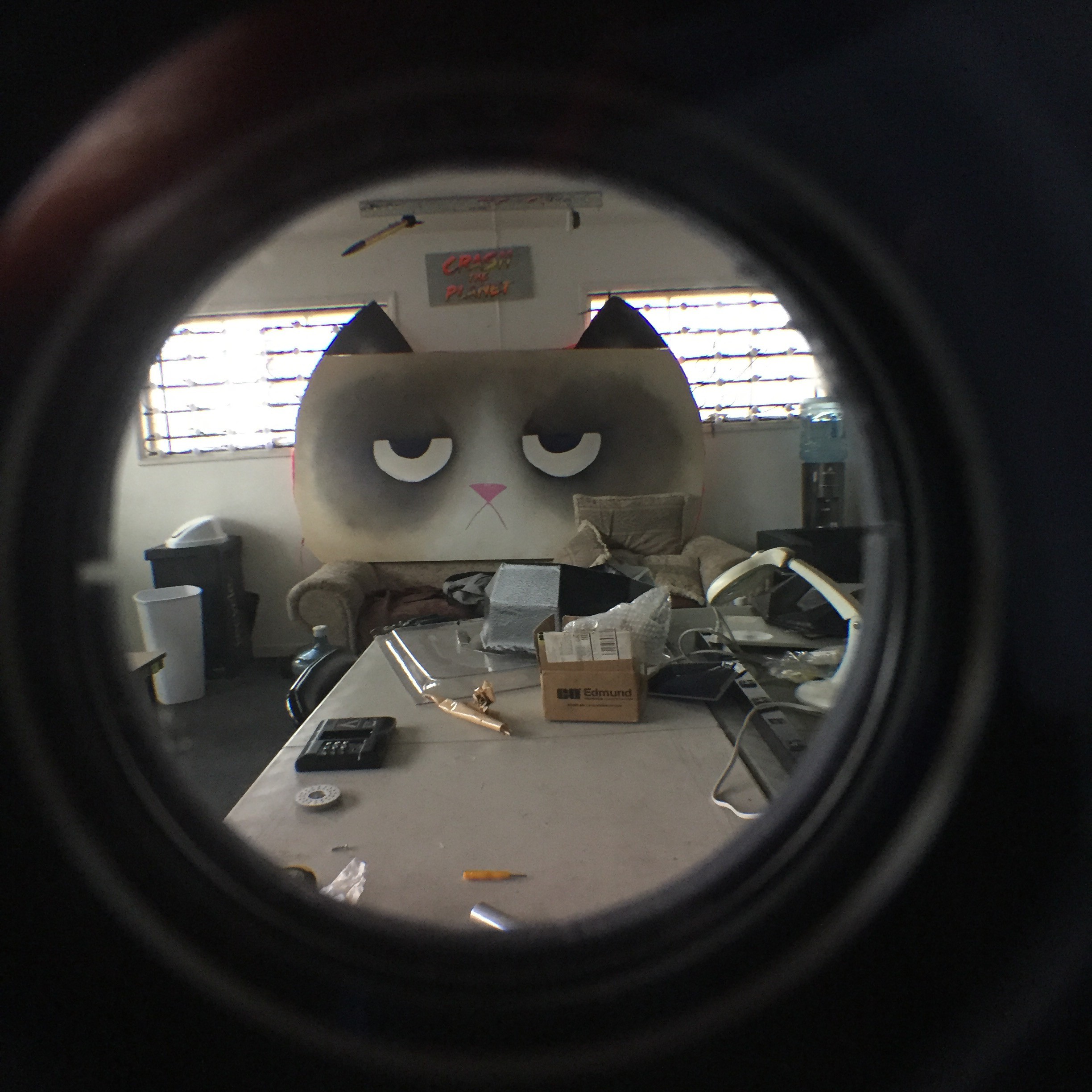
Grumpy Cat approves.
![]()
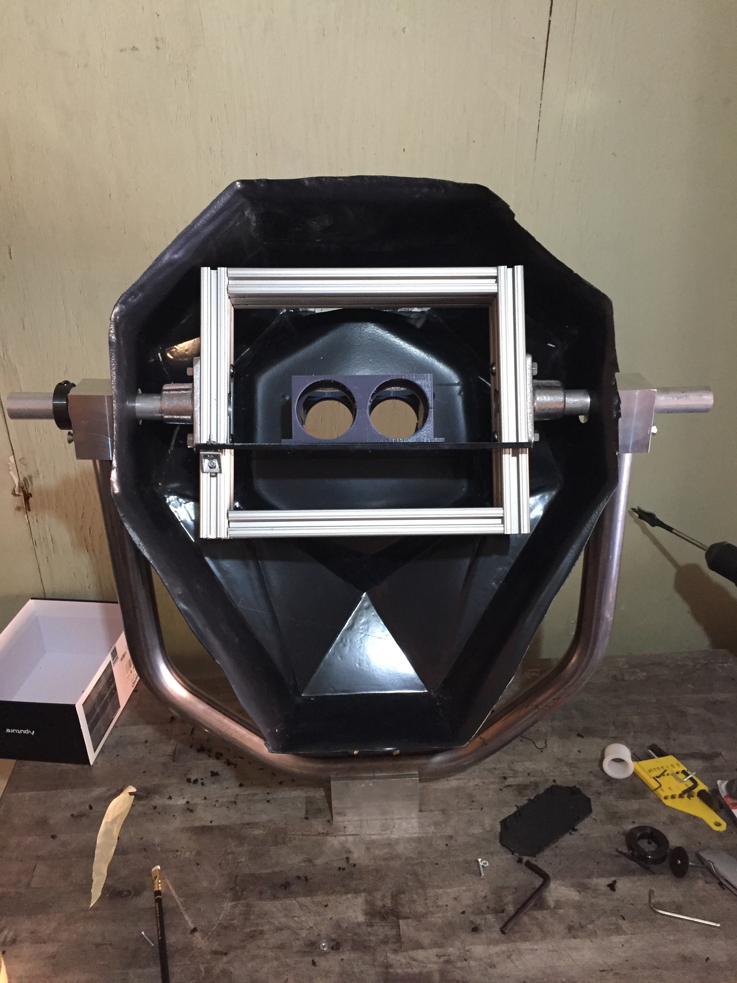
I finished the work back home, where I took a dremel to the vacuum formed shell so it could mount properly onto the frame and yoke.
![]()
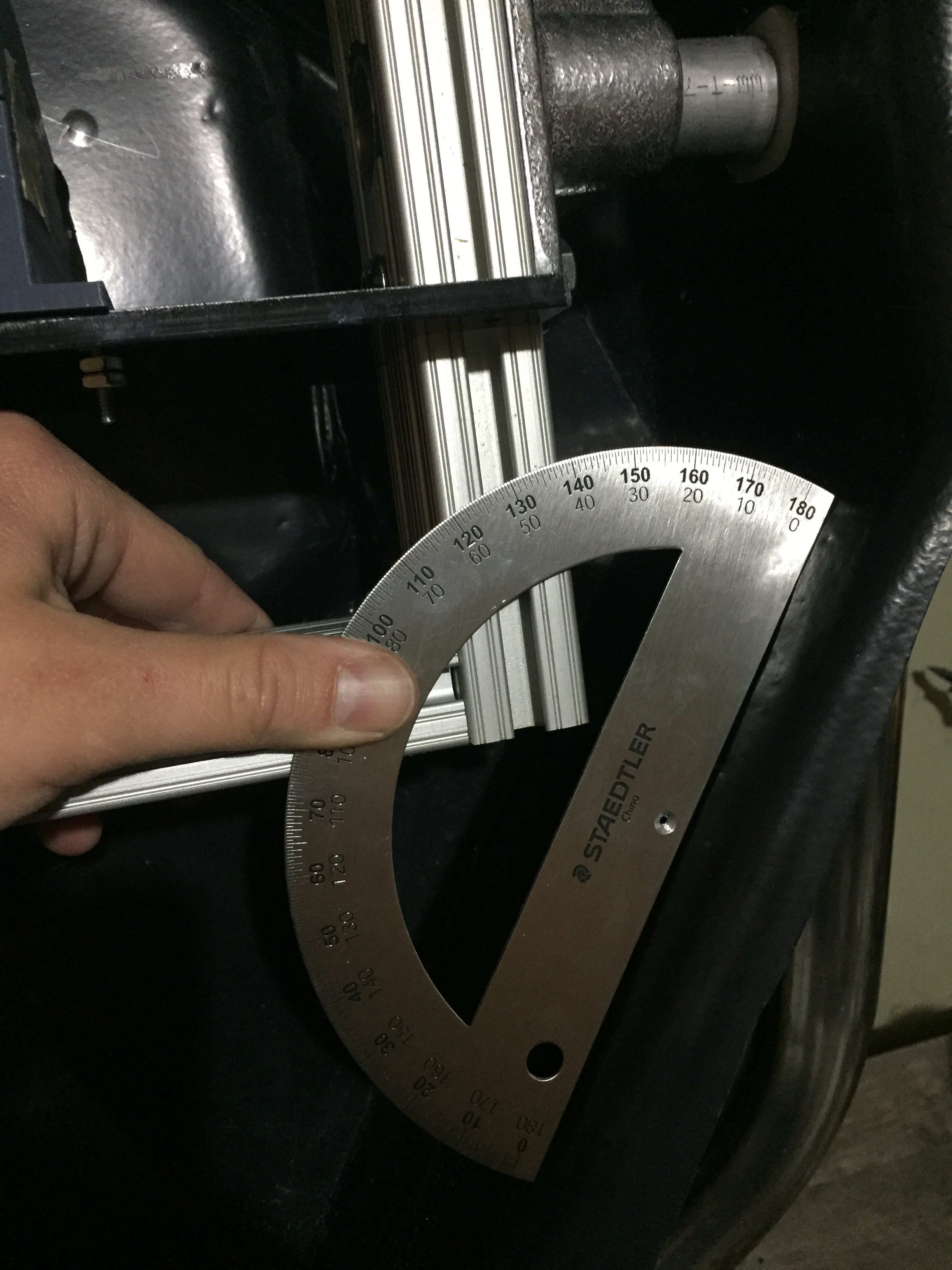
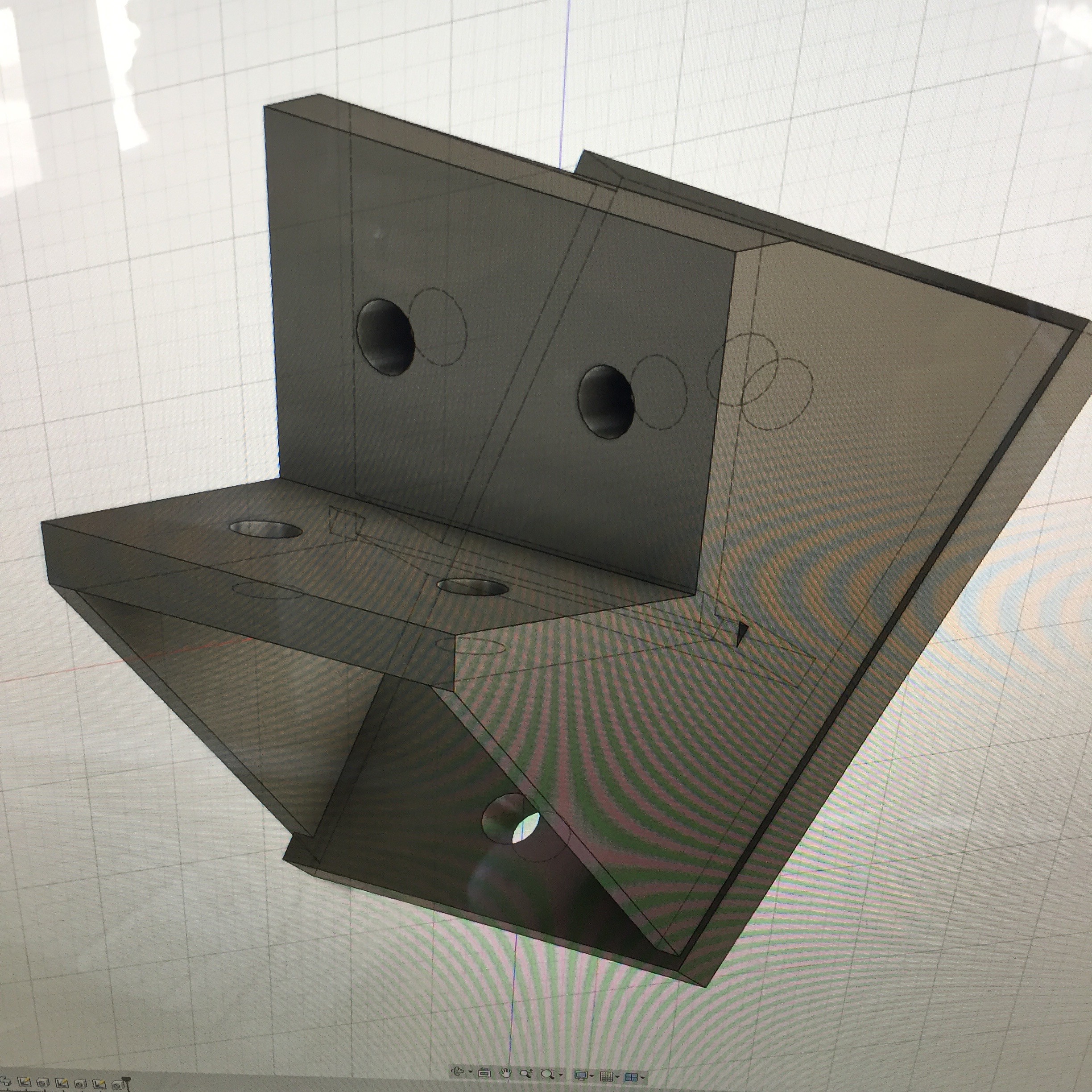
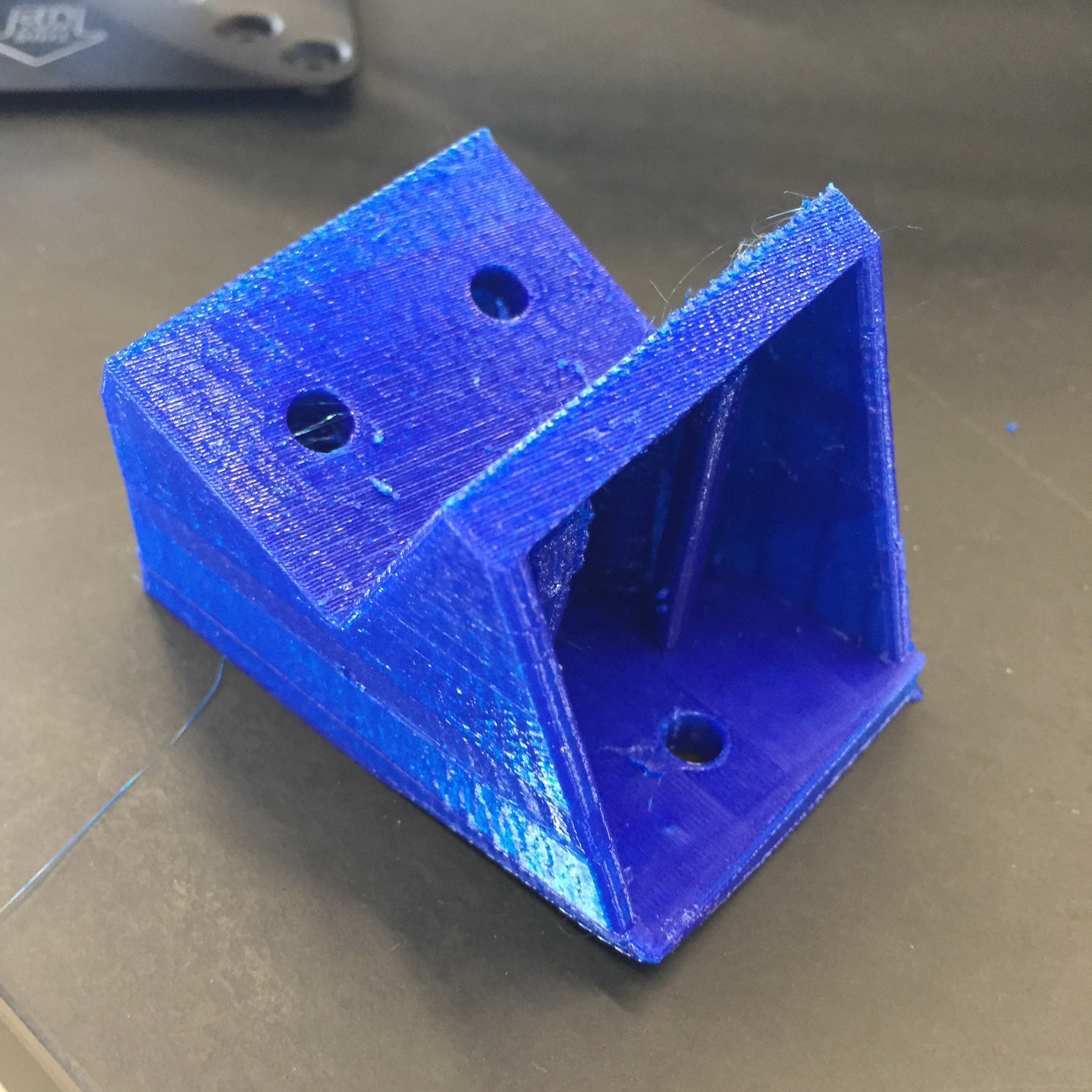
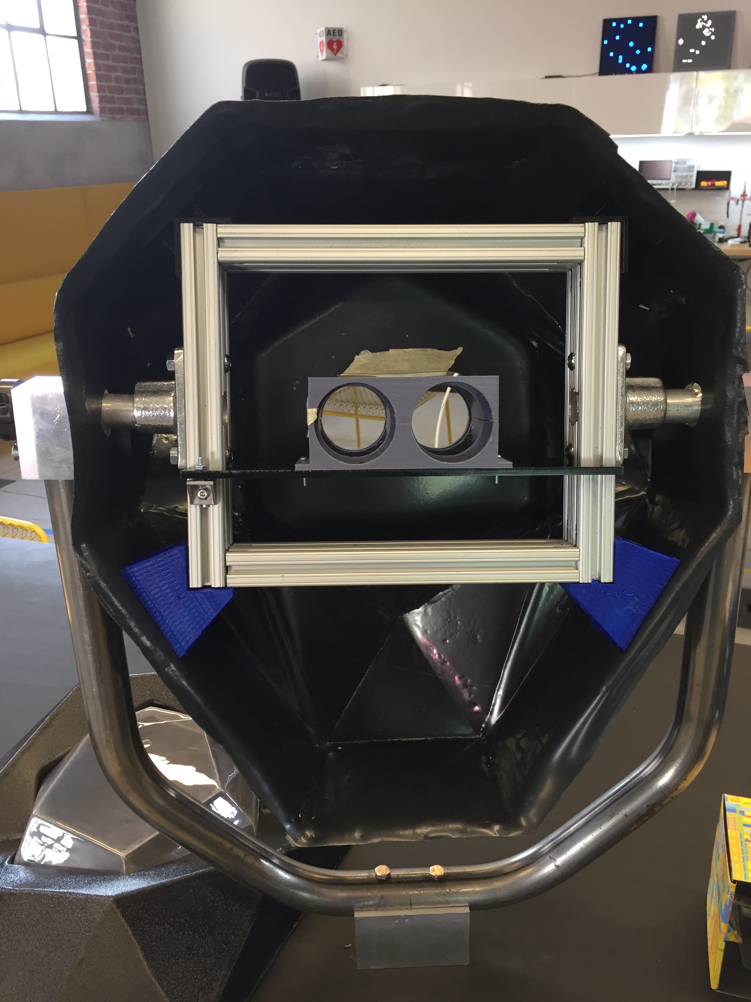
For the shell to be solid, we'd need to use some sort of mounting bracket between the corner of the 8020 frame and the skin of the shell. I did some measurements and then focused on design.
![]() The geometries are a bit tricky right there. I'd have to take into account both the angle of the shell relative to the corner of the frame, as well as the outward draft angle of the shell itself.
The geometries are a bit tricky right there. I'd have to take into account both the angle of the shell relative to the corner of the frame, as well as the outward draft angle of the shell itself.![]()
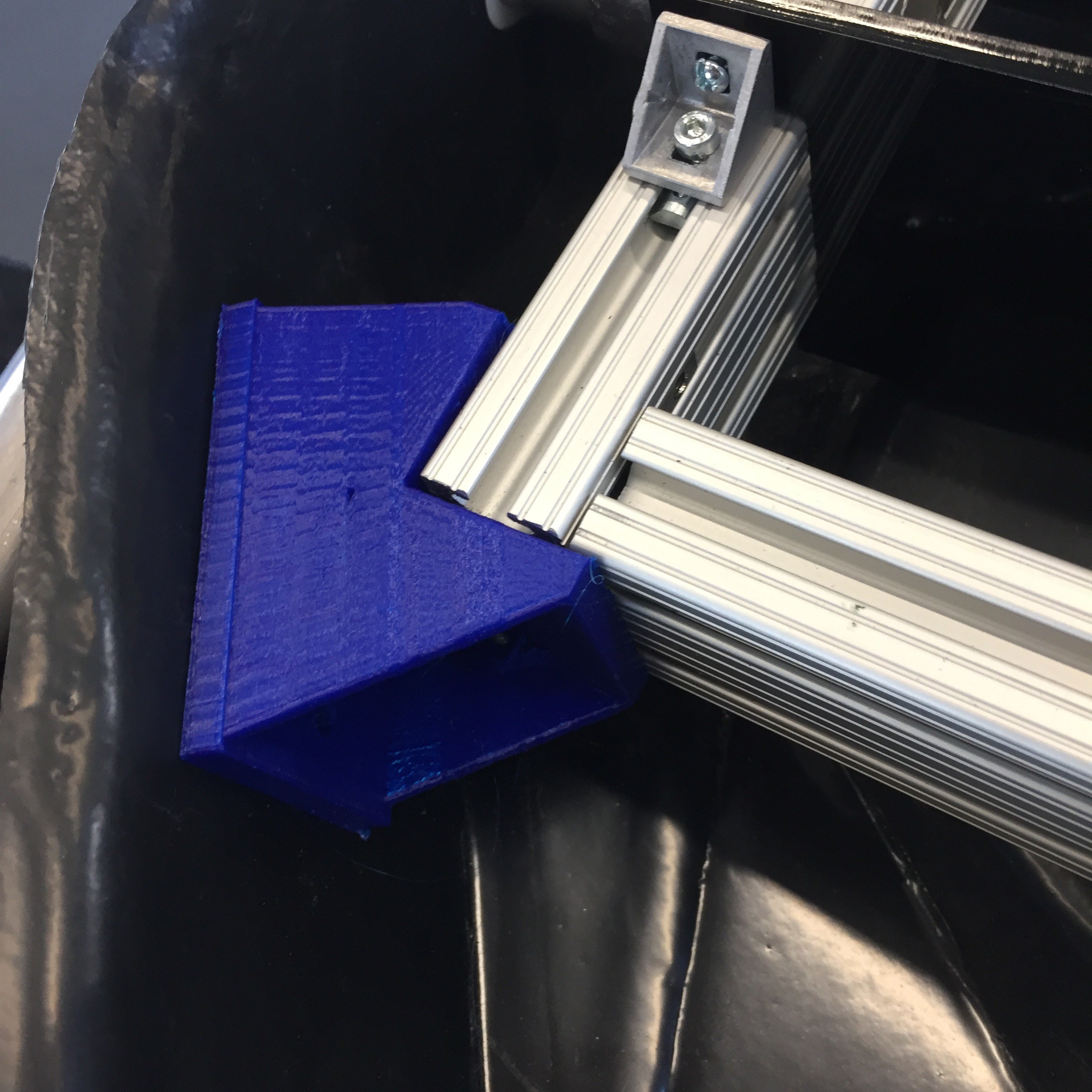
I printed it at the Lab and focused on mounting all the remaining components.
![]()
![]()
The fit looks just right, and the shell feels firmly attached.
![]()
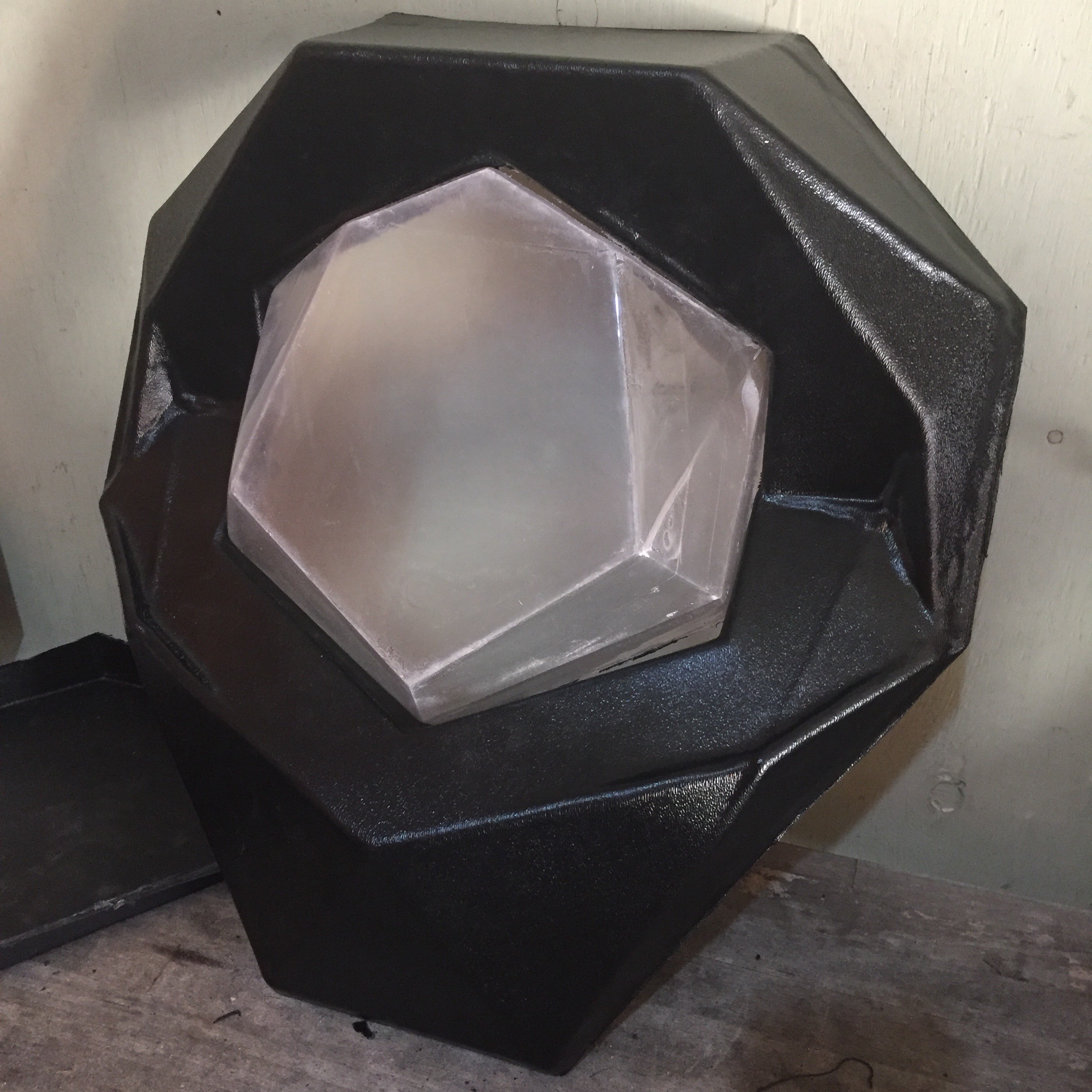
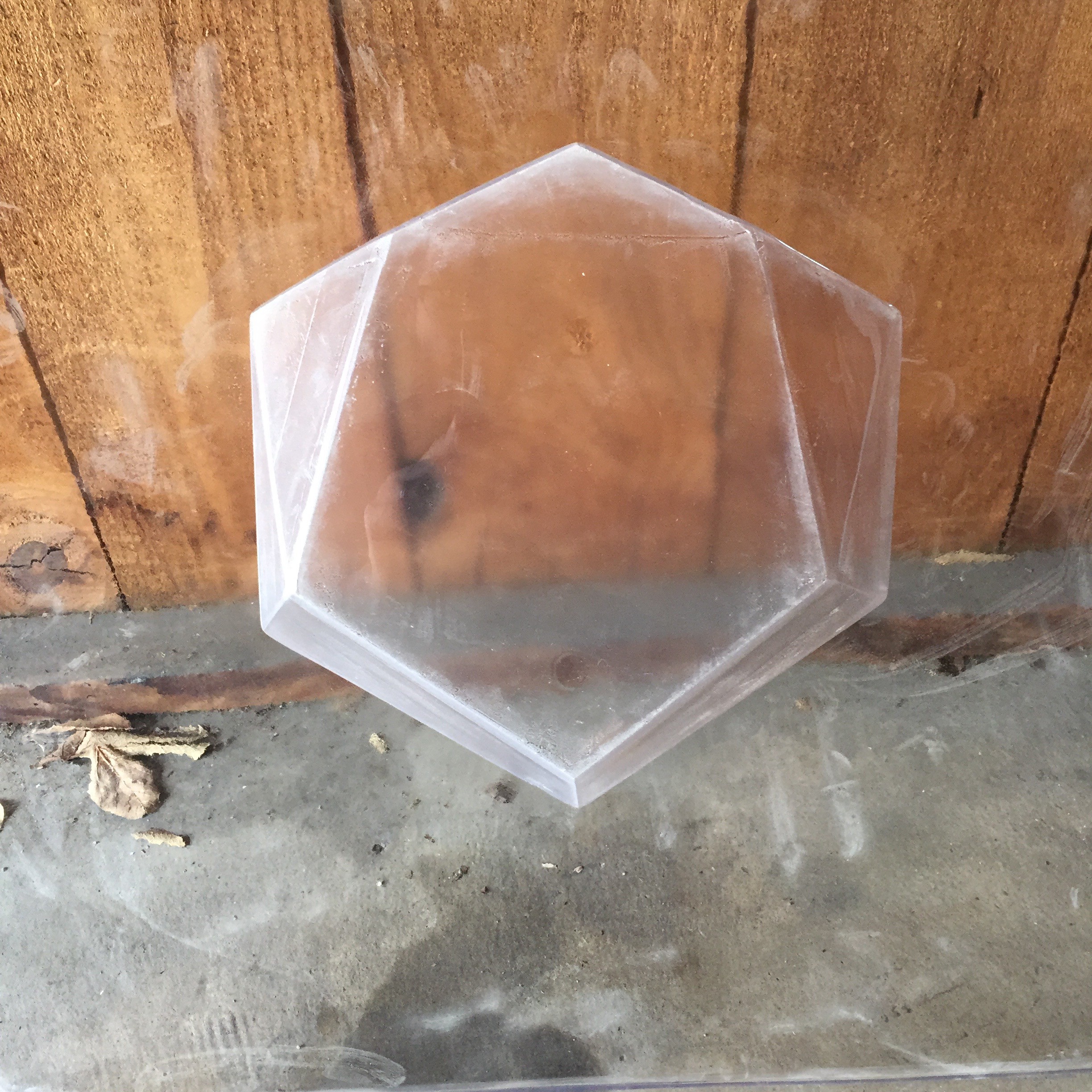
To finish up the front half of the shell, I'd need to find a way to clear up the fogginess of the window. Though I had used bondo and fine grit sandpaper to make my vacuum form buck as smooth as possible, the interior of the PETG window still came out a bit rough, diffusing the light that passes through it when it hits that side.
I'd need to take on some sort of polishing step to make it transparent.
![]()
Vapor polishing was the first idea I had. However, I came to discover PETG doesn't respond to typical solvents like acetone, and I'd need to work with some pretty hazardous and difficult to acquire chemicals.
There were a few options. Flame polishing could heat the plastic up to remelt it smooth. An orbital sander with increasingly finer grits of polish could smooth it out by removing material from the rough side. I could try painting it with a transparent clear coat that would fill in the roughness, but I'd probably need to take into account refractive issues where the plastic meets the paint.
![]()
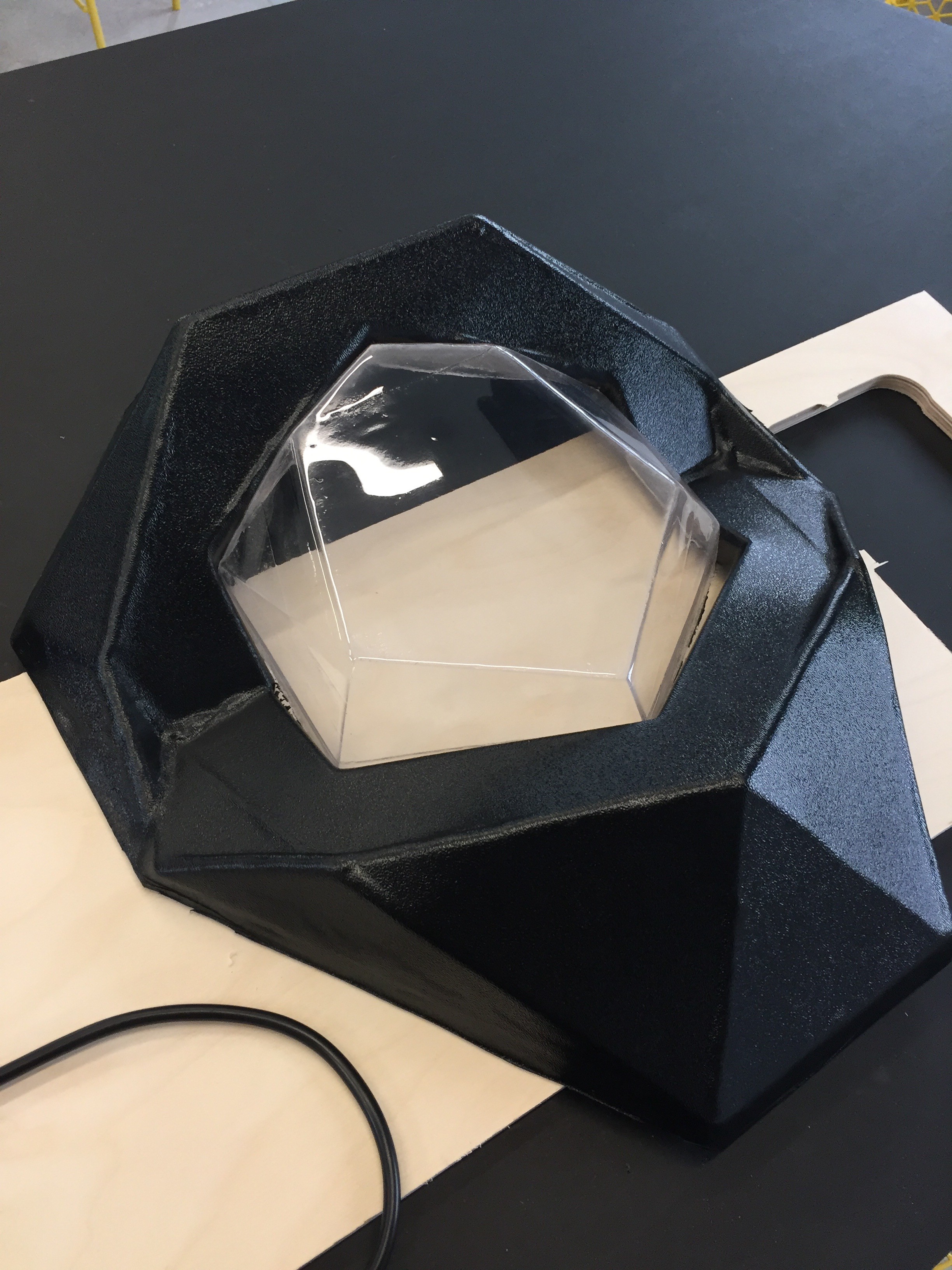
Heat seemed like the best solution. I wouldn't need to introduce any new substances to the window, and it could potentially go fairly quickly.
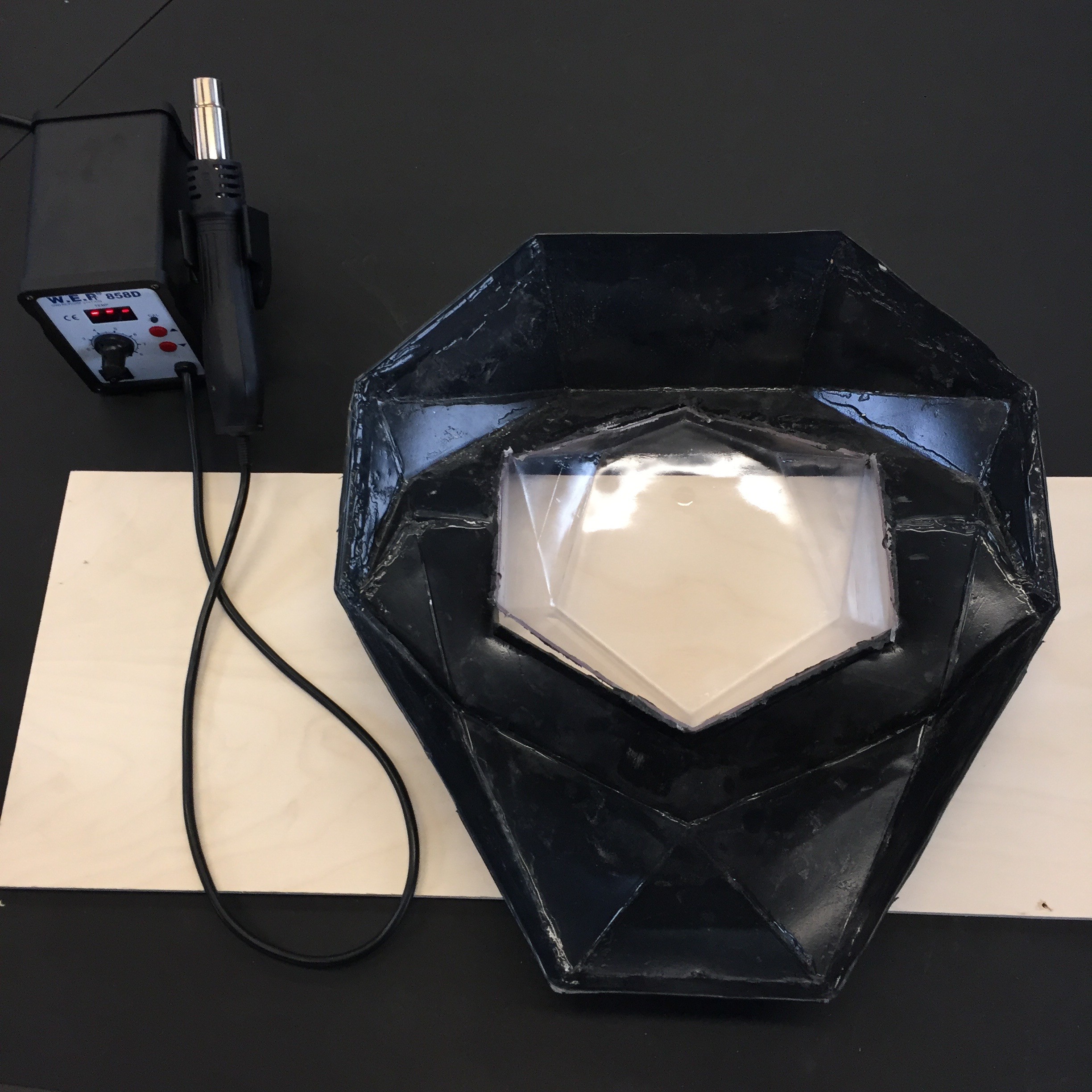
I didn't have a torch at hand, and I was concerned about potentially burning or bubbling the plastic, so I grabbed one of the hot air rework stations at the lab and tried an experiment.
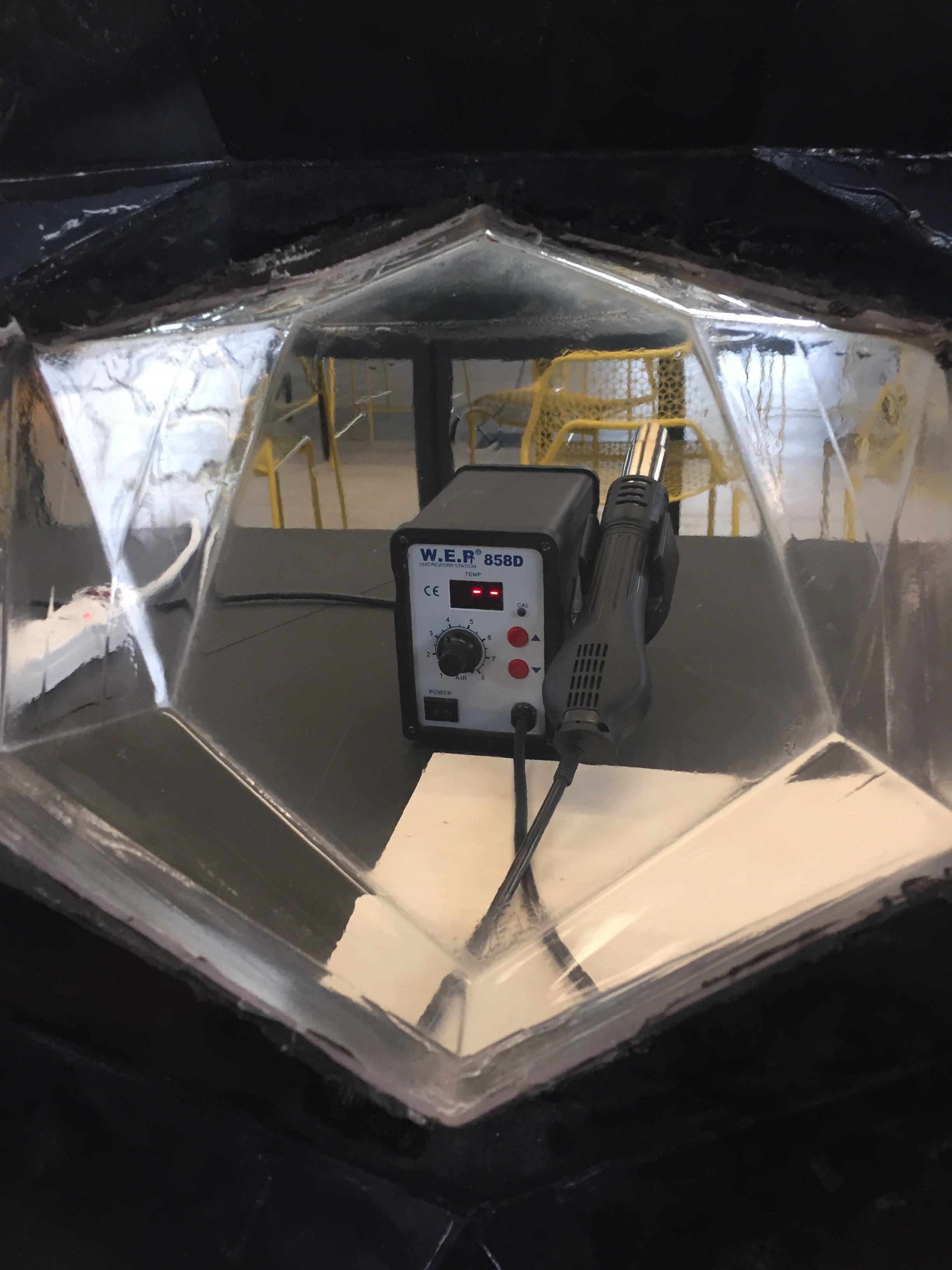
As I blew hot air over the rough side, I could see it starting to smooth and melt down. I increased the temperature to around 500 degrees and moved quickly. The results speak for themselves
![]()
![]() Feeling inspired by the power of hot air, I took the rework station to the edges of the shell, and heated up the ABS so I could bend the excess plastic inward. Cleaned up and mounted, the main assembly of the newest Perceptoscope is complete.
Feeling inspired by the power of hot air, I took the rework station to the edges of the shell, and heated up the ABS so I could bend the excess plastic inward. Cleaned up and mounted, the main assembly of the newest Perceptoscope is complete.![]()
-
Old Box / New Shell
12/07/2016 at 23:33 • 2 commentsWe've been in incubation for a little bit, working on our tooling for the shells so we can start putting these dev kits into production. Today, I wanted to start with a look back. Digging through some old photos I found something cool I never realized I had... the first original Perceptoscope prototype!
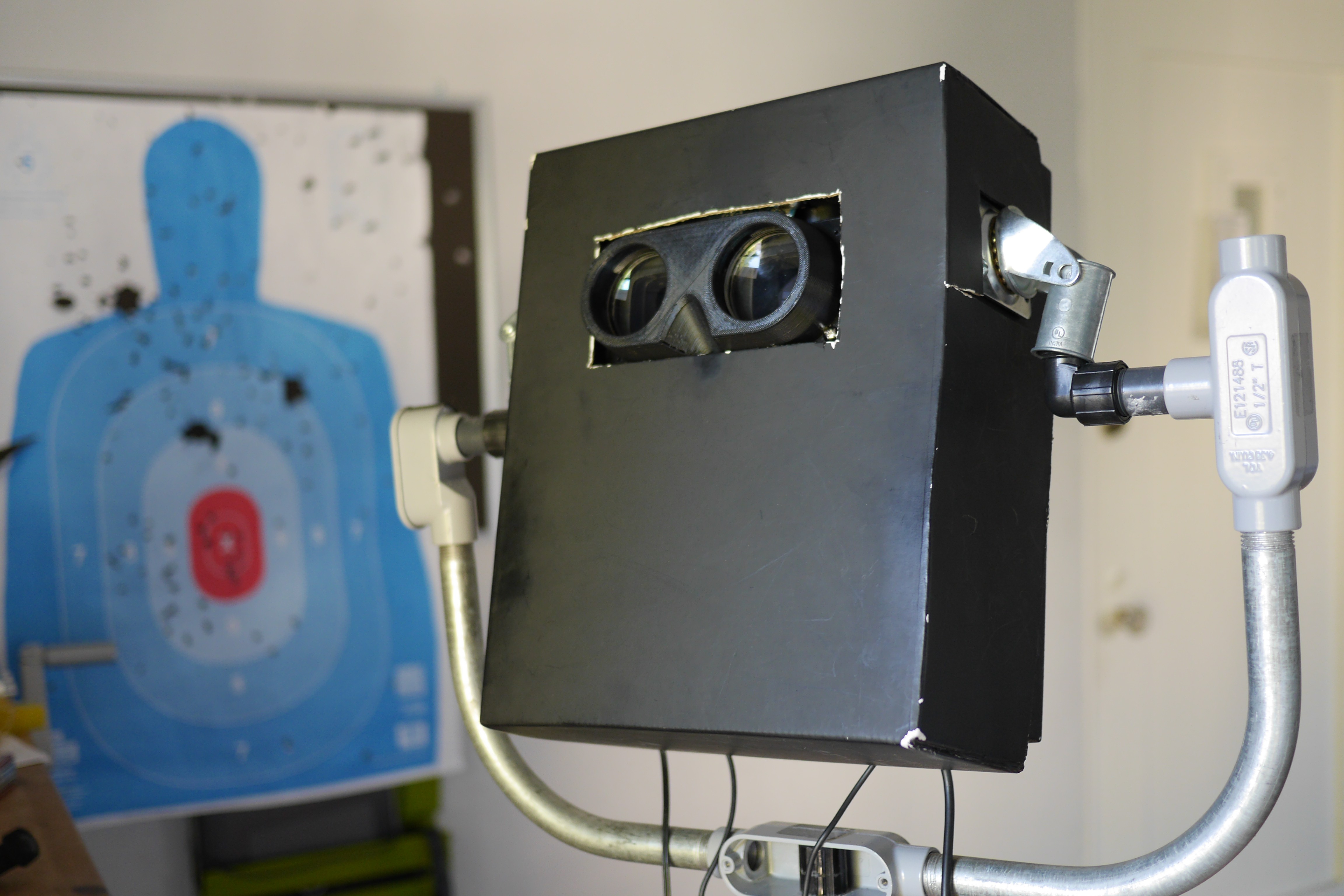
This was built out some cardboard boxes, a music stand, a pair of disassembled casters, and some random electrical conduit and other junk I found around a hardware store. At this point I had built the optics, but needed a way to test them at eye level.
I didn't have all the mechanical tracking implemented yet, so I wired up an MPU 6050 to an Arduino, which uses an onboard DSP to do all the sensor fusion between its accelerometer and gyro. It wasn't the ideal for the long term, but was a good way to start playing with movement quickly.
At this point the Scope was running tethered to my laptop, and required really long usb and hdmi extension cables. It wasn't a long term solution, but got me through some of the early days of testing.
It's a pretty stark contrast to where we've taken the project since, but it's cool to see just how far this has come.
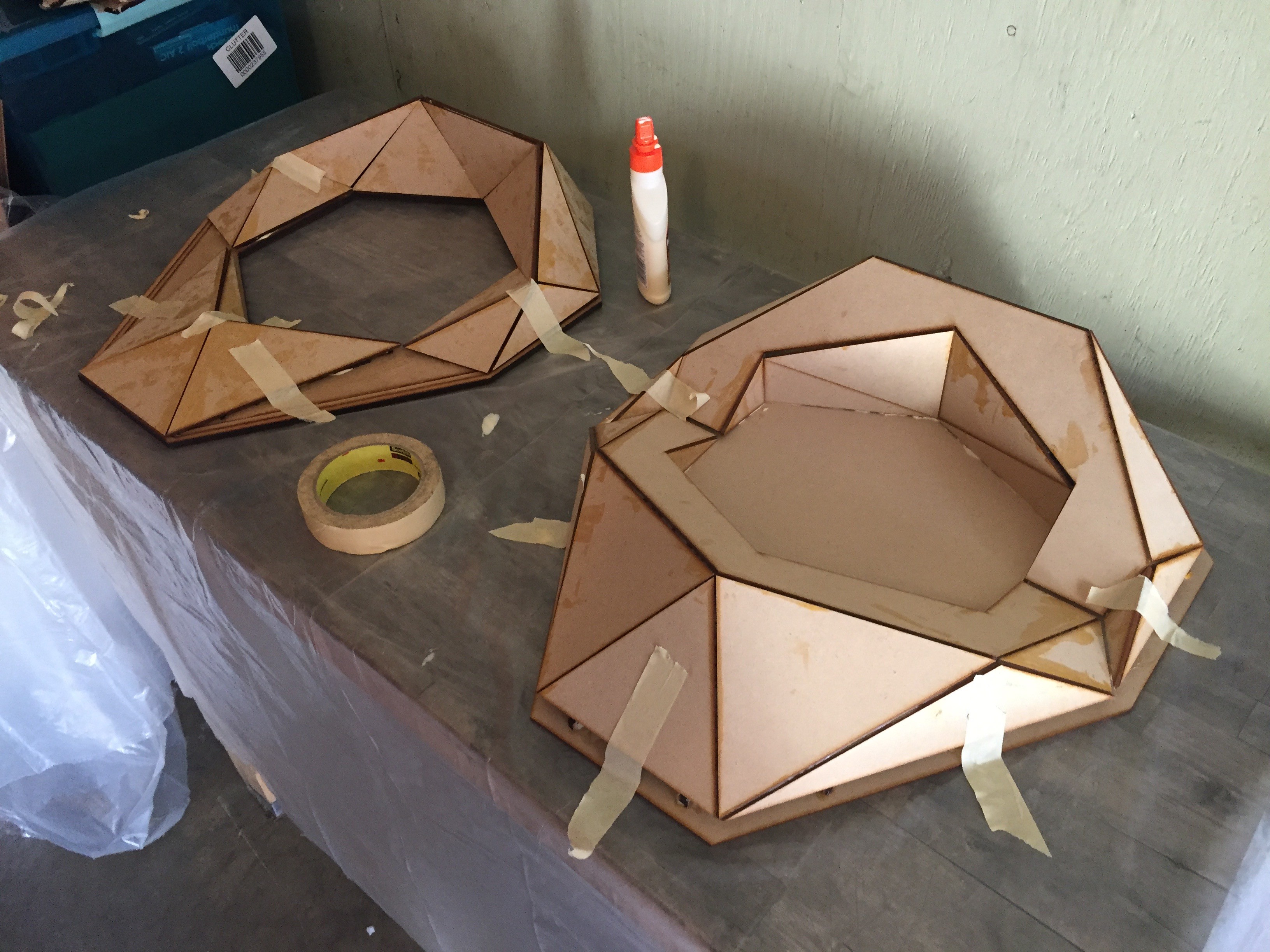
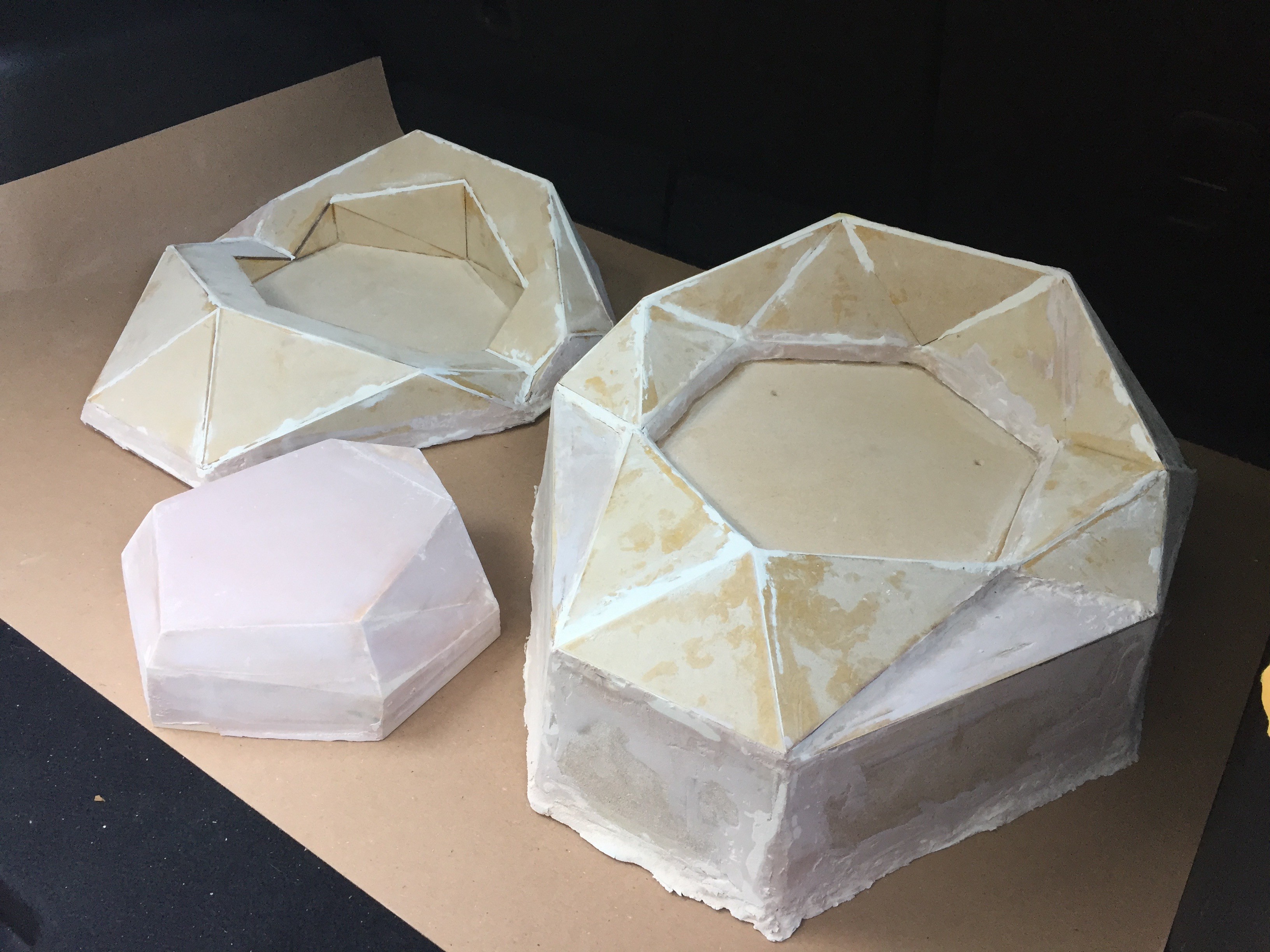
In terms of the latest shell manufacturing, the last approach ended in less than perfect results. To keep things moving, I got to building out some new bucks for vacuum forming. The vacuum pull is extremely strong, so it's important to make them much more of a solid object than I had previously attempted.
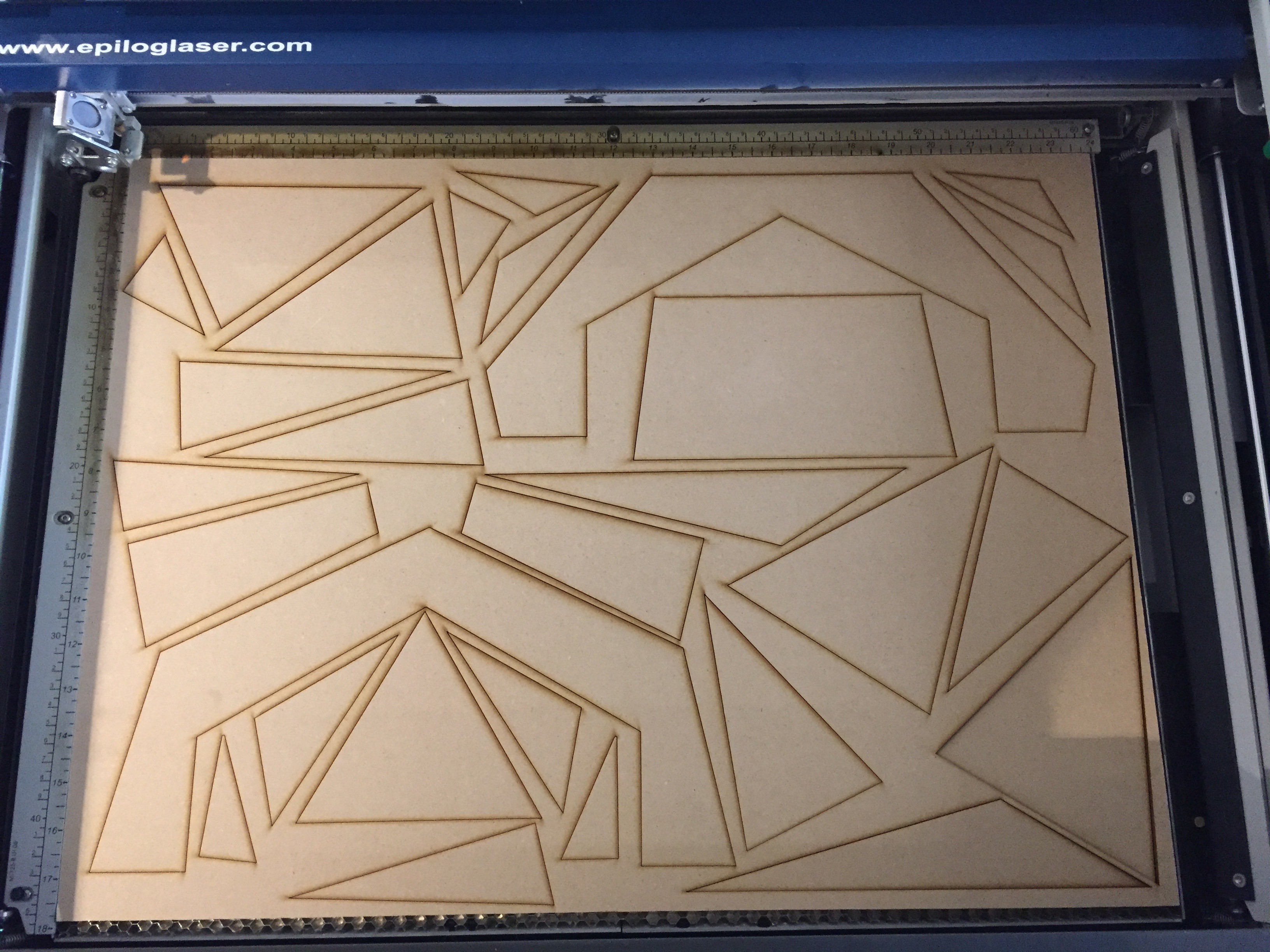
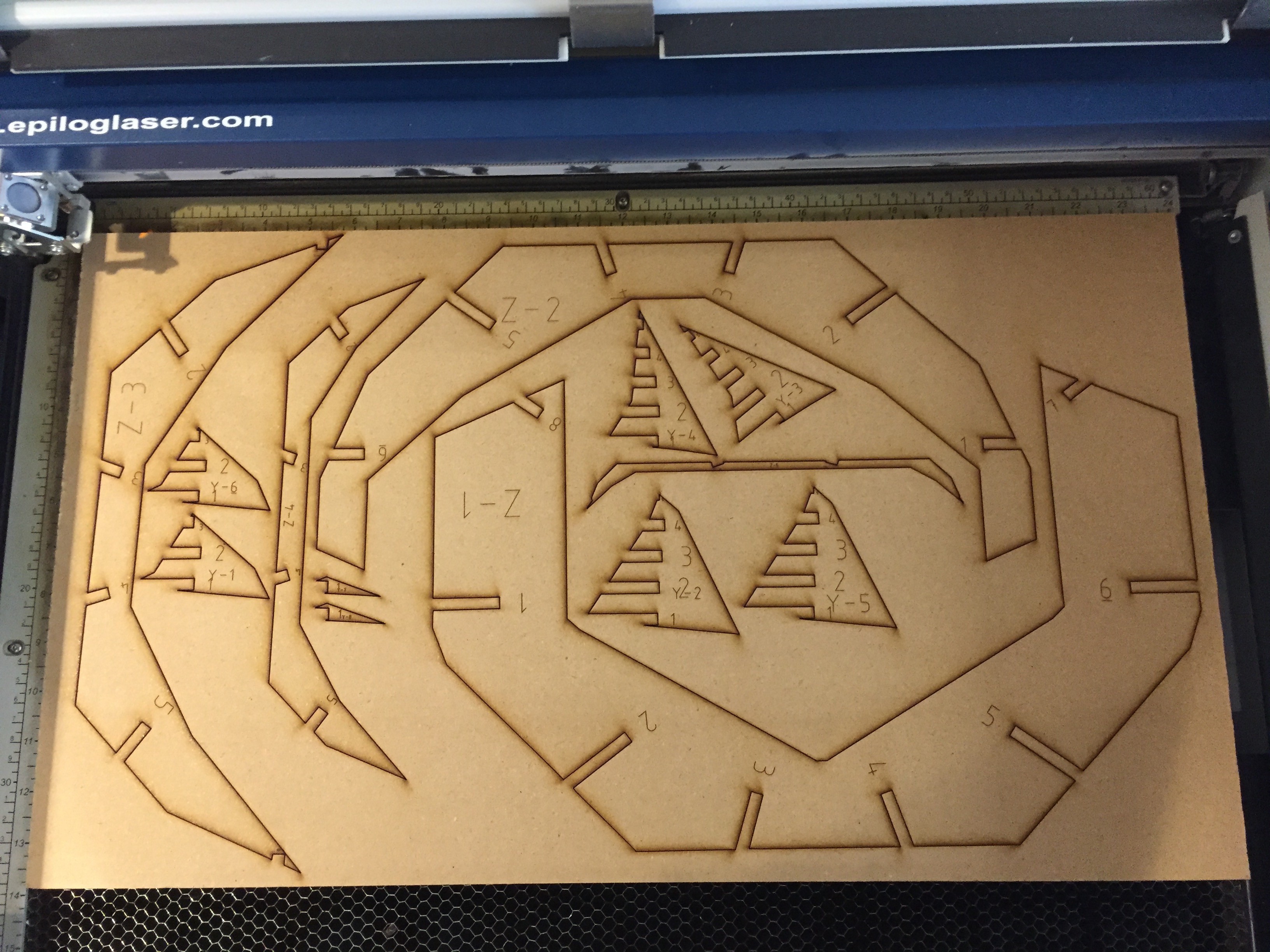
To start, rather than use the folded card stock panels, I laser cut new facets to attach to the ribbing I had already generated out of 1/8th inch MDF.
![]()
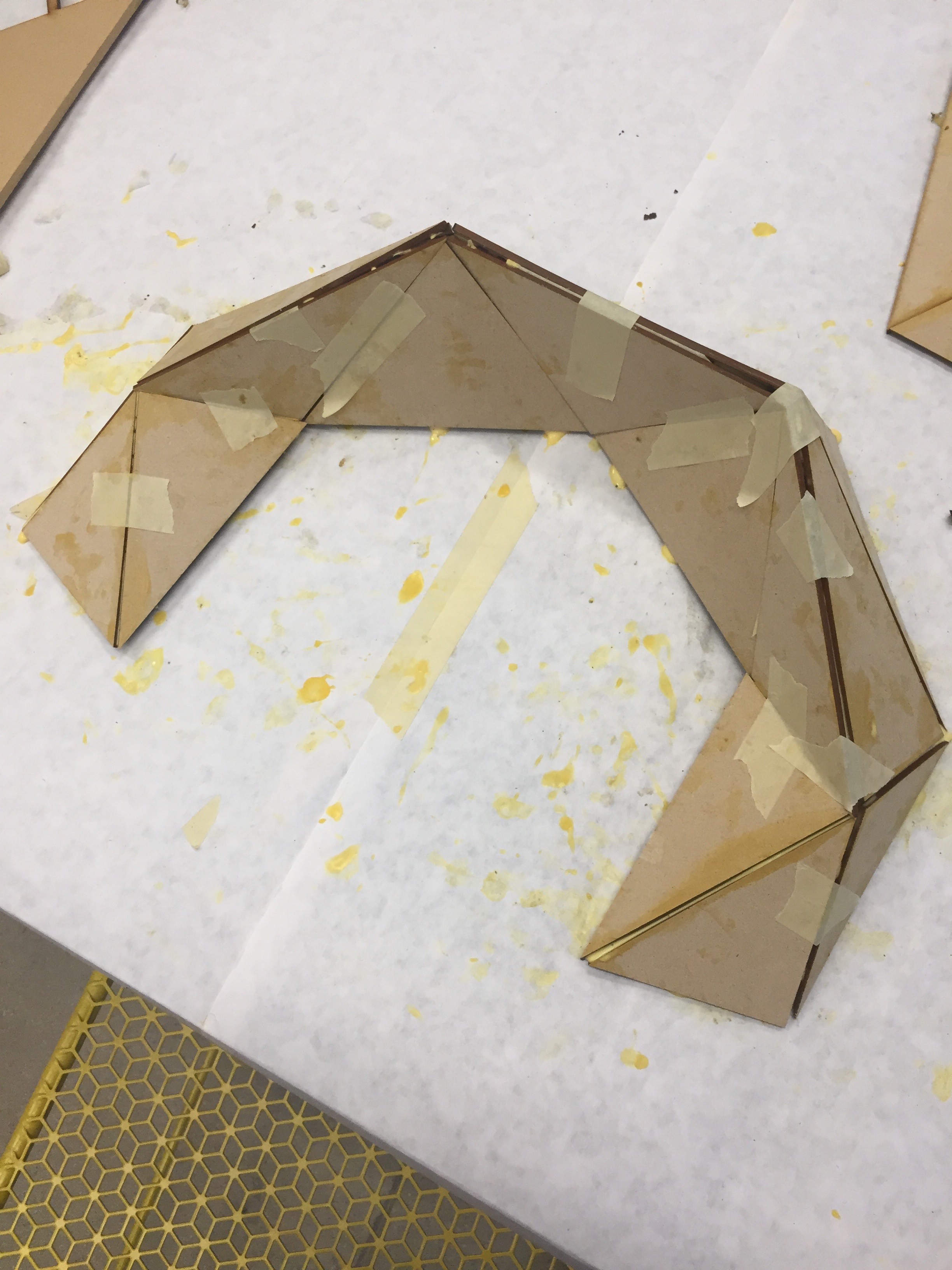
I used some masking tape internally to set it up for a test fit against the ribs. Looks like a good start.
![]()
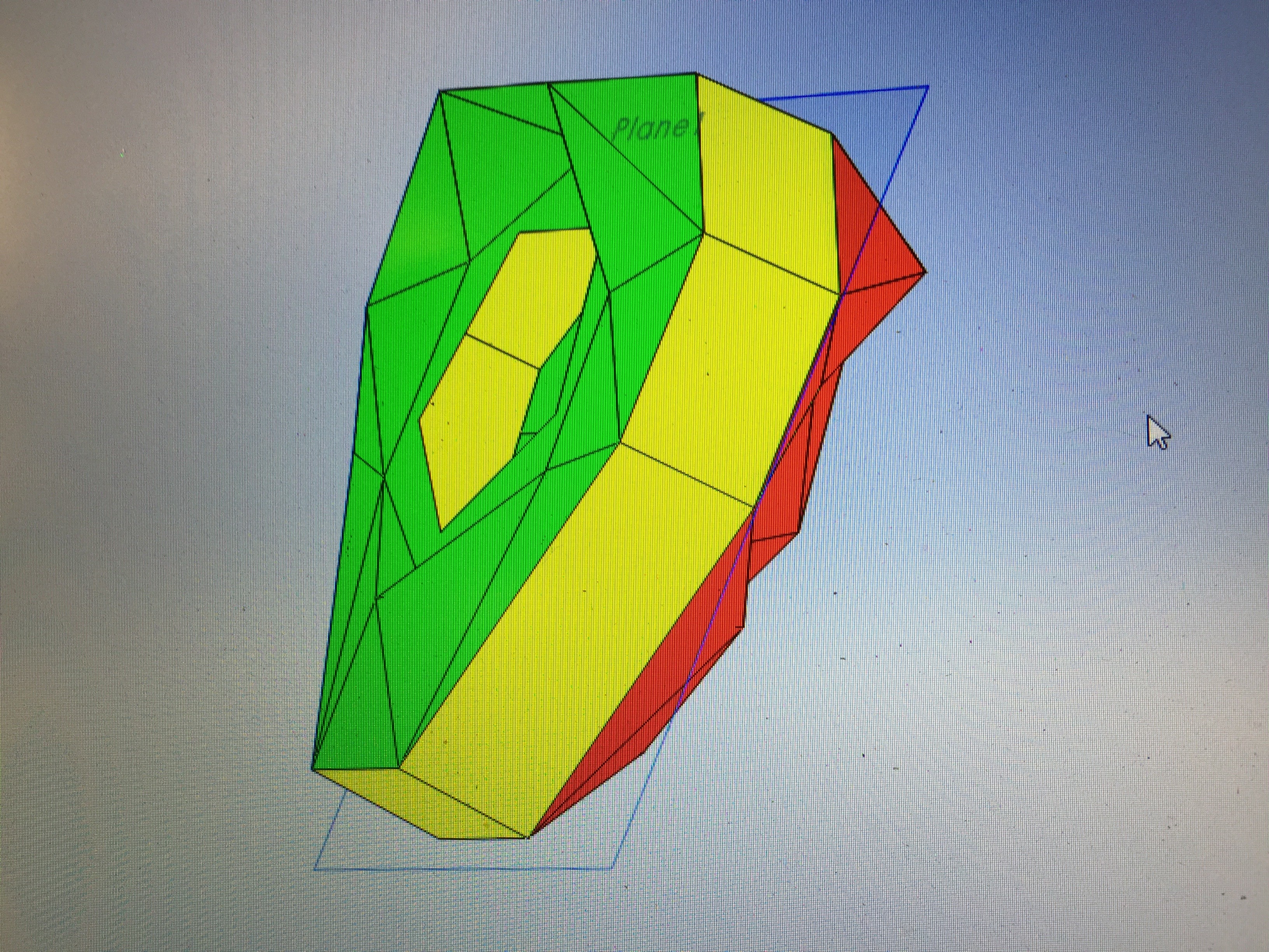
The opposite side of the shell was having some drafting issues with its shroud. I'd need to refabricate that part to make sure the vacuum form could release from the mold. I modified the design slightly and did a drafting analysis. Looks like it should be able to release.
![]()
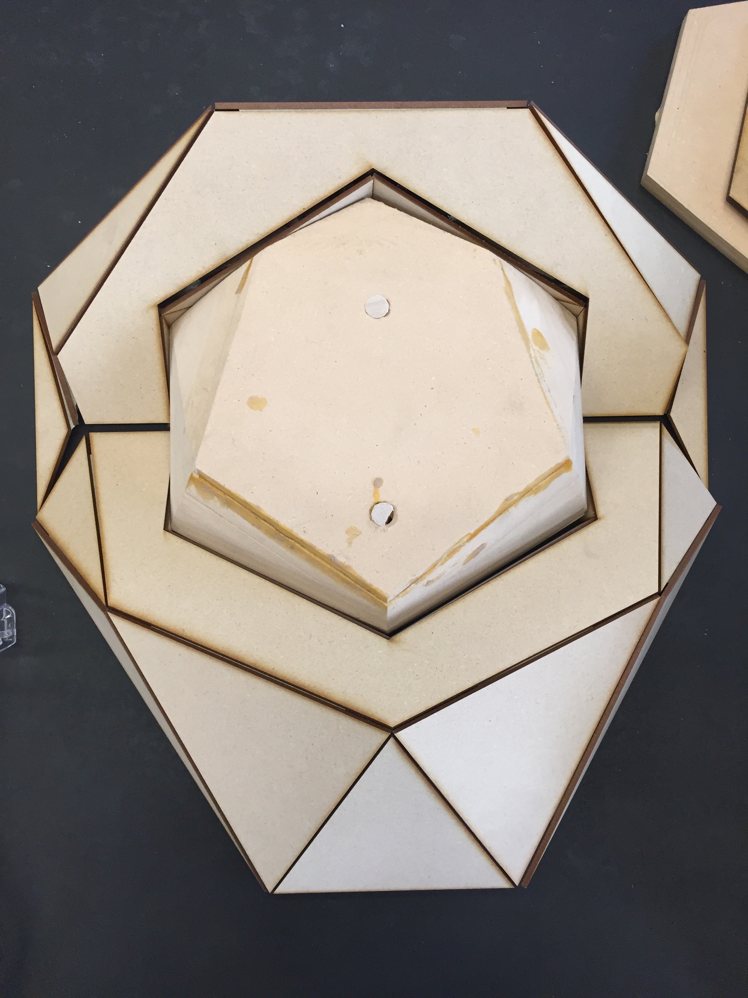
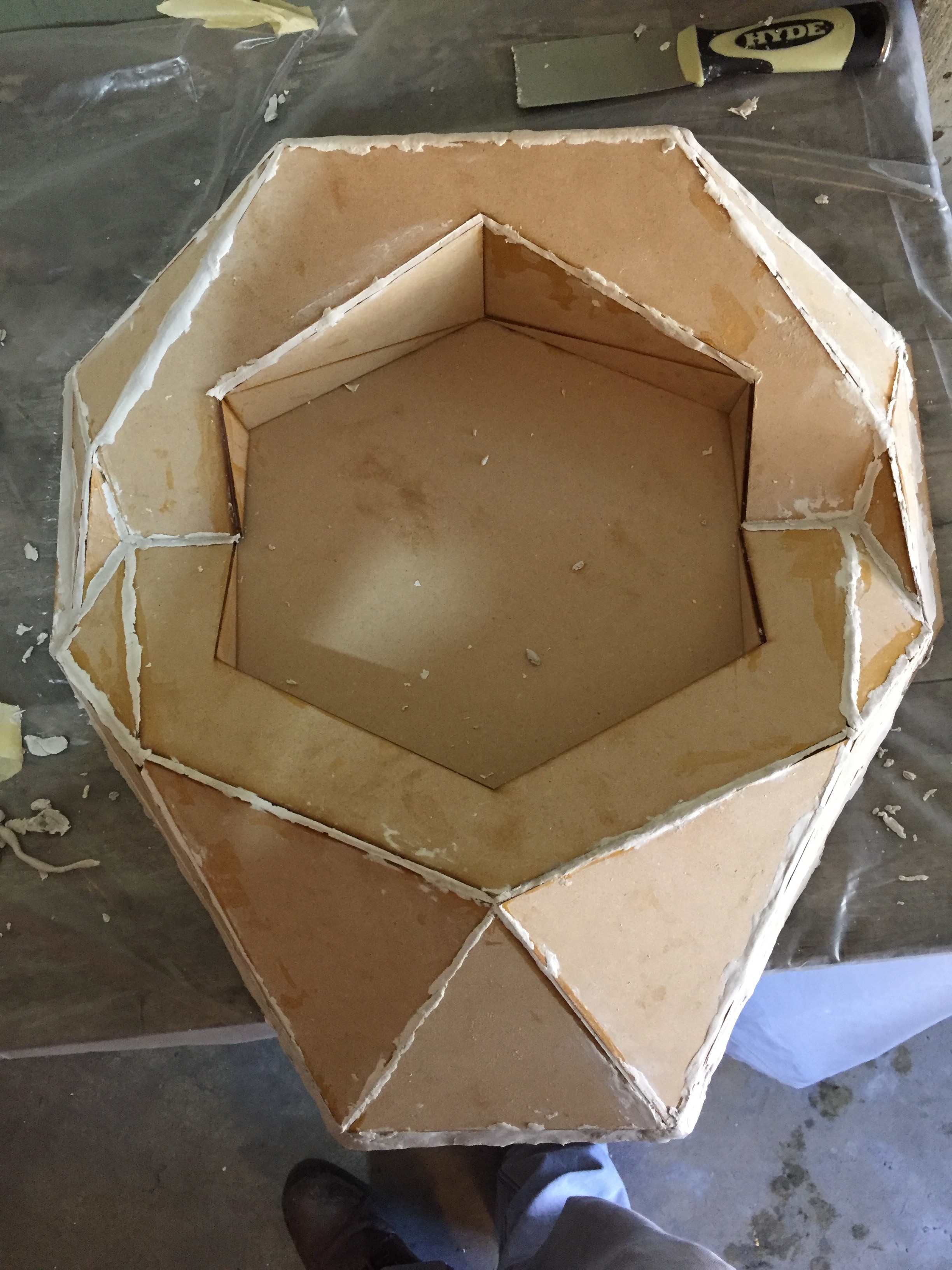
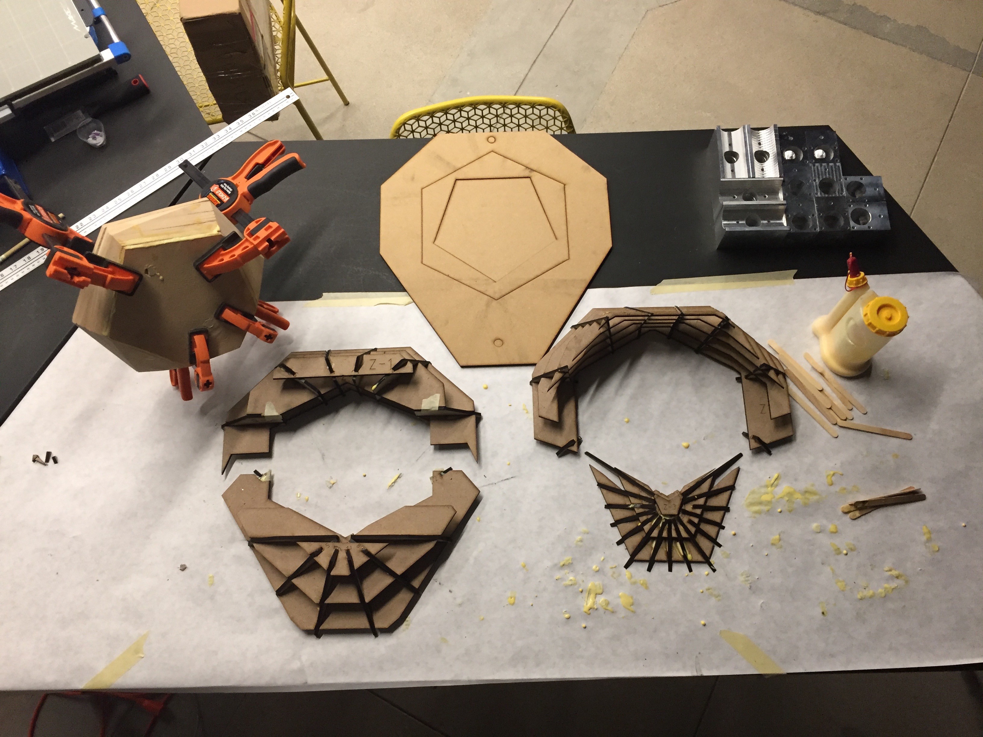
I laser cut another set of ribbing, and then glued it up to the other facets.
![]()
![]()
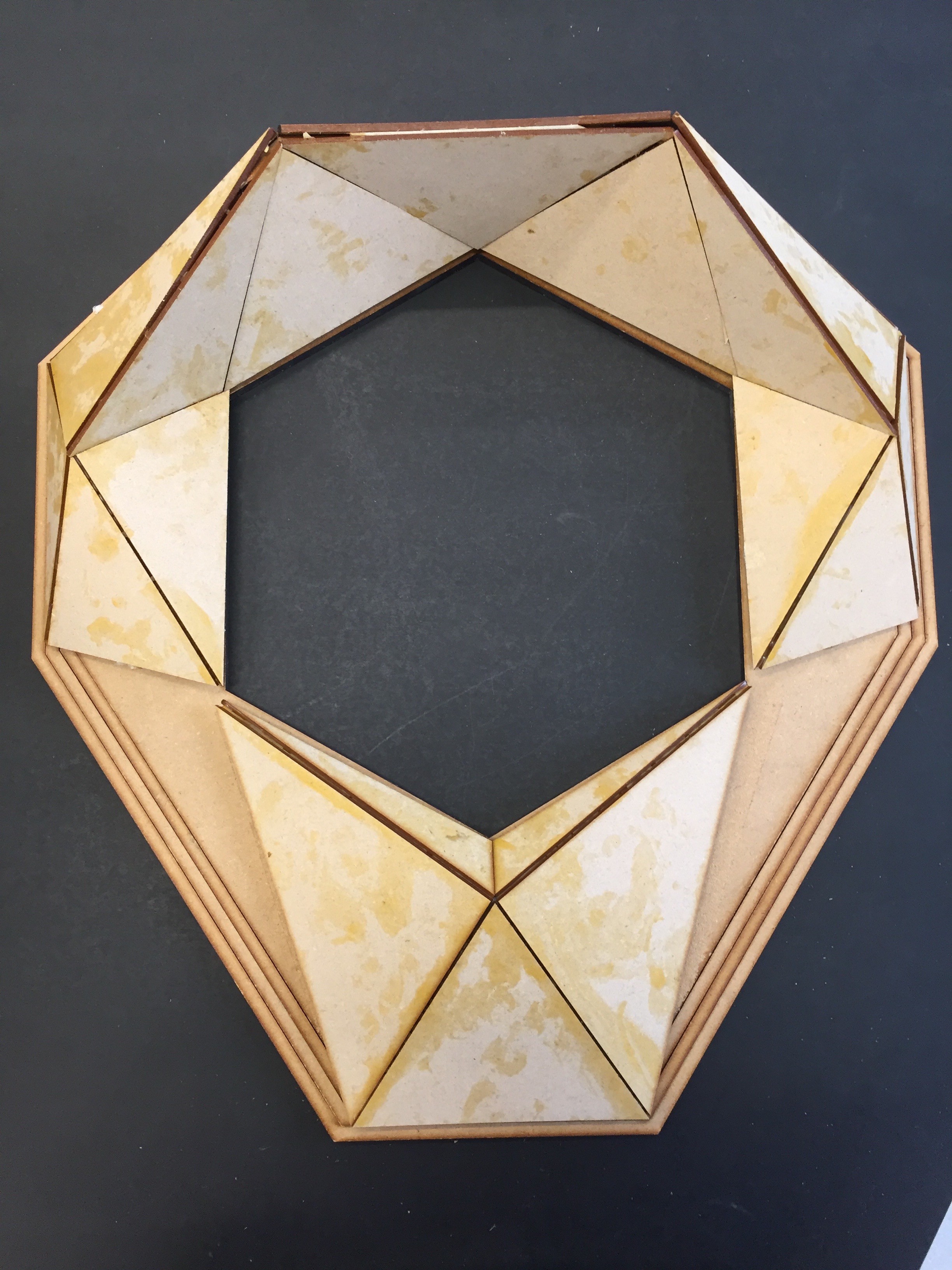
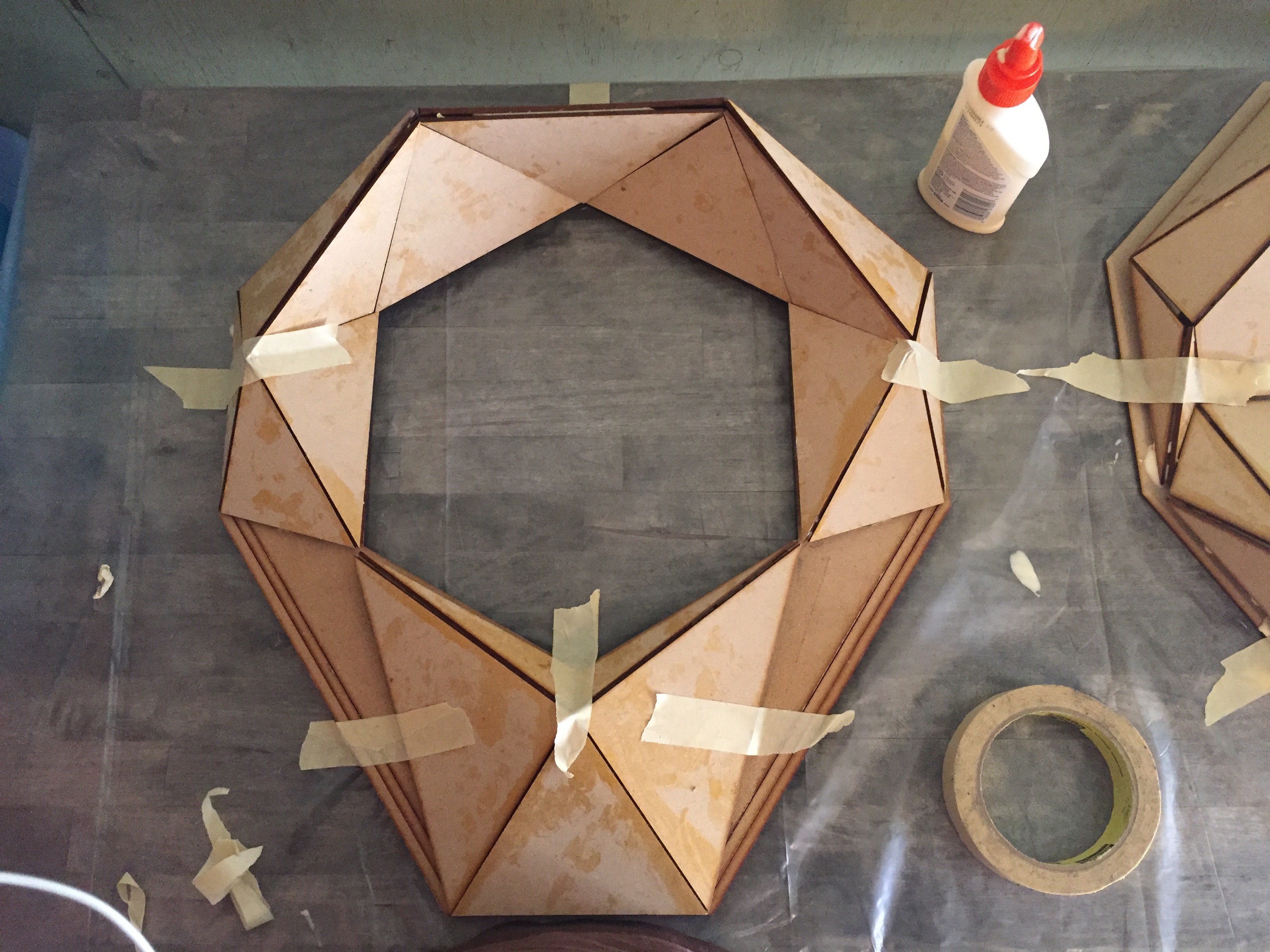
Here's the complete side with all the new faceting glued up.
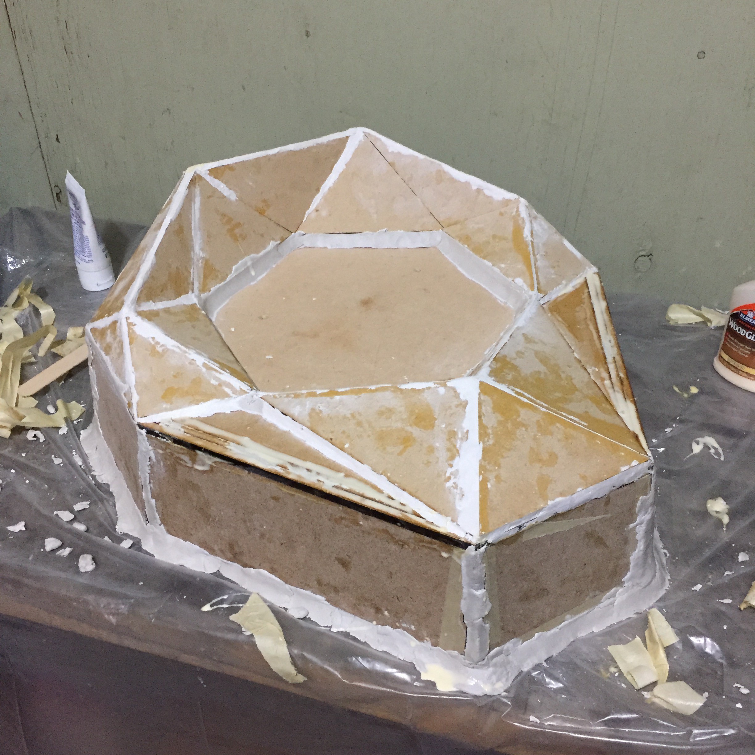
![]() Now I just needed to glue all the pieces together to a backing board, and start filling in all the gaps that remain.
Now I just needed to glue all the pieces together to a backing board, and start filling in all the gaps that remain. ![]()
![]()
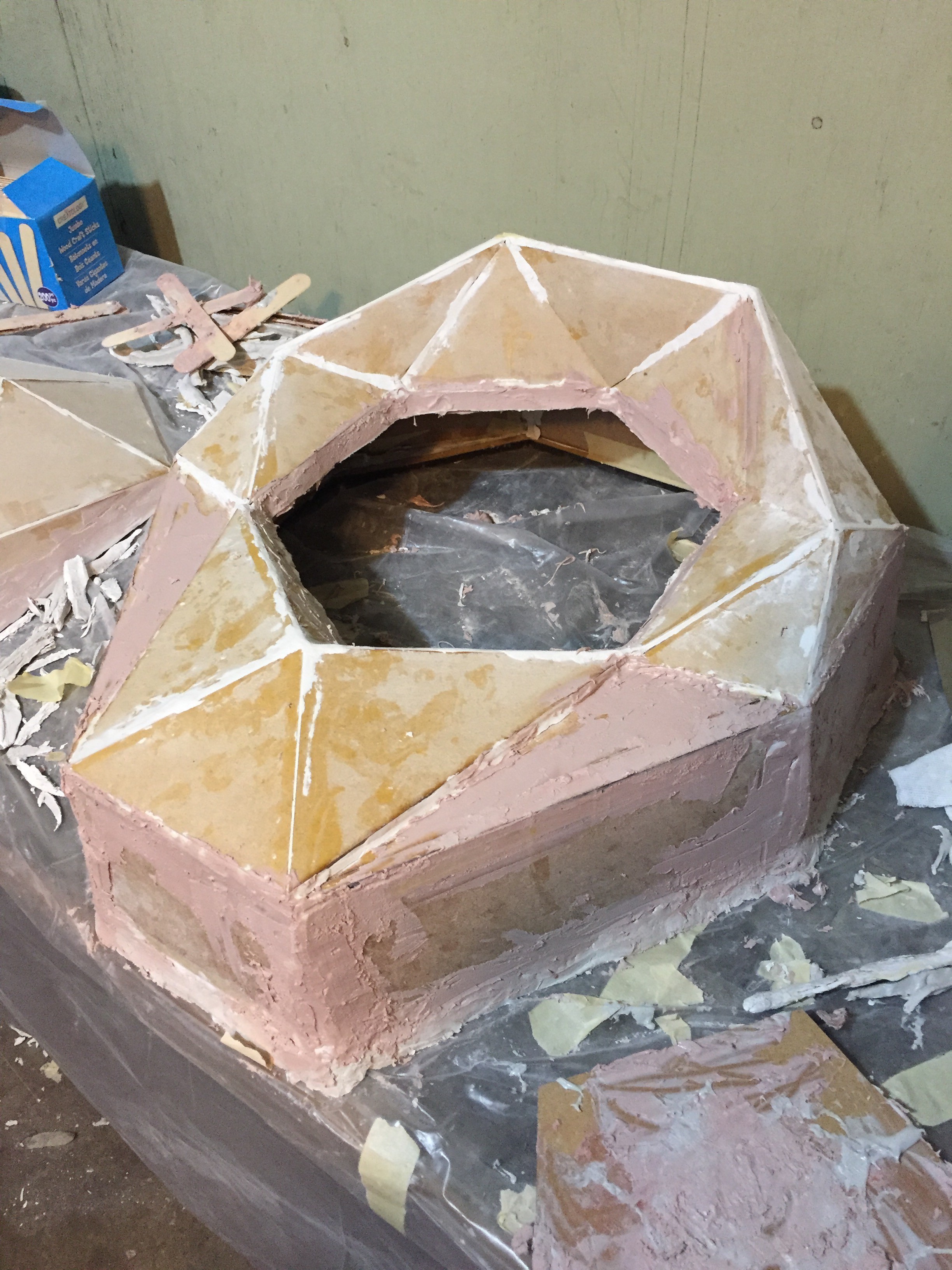
I started with modeling clay since it would be easy to work with, air dry, and I could sand it afterwards.
![]()
The opposite side of the shell would be attached to a much bigger backing piece, that would give us most of the depth of the shell. I made sure to add drafting to the those side walls of about 3 degrees so the sides could release.
![]()
The clay did decent, but there were still some gaps to fill. After letting it dry, I started working with some bondo body filler to finish it up before sanding.
![]()
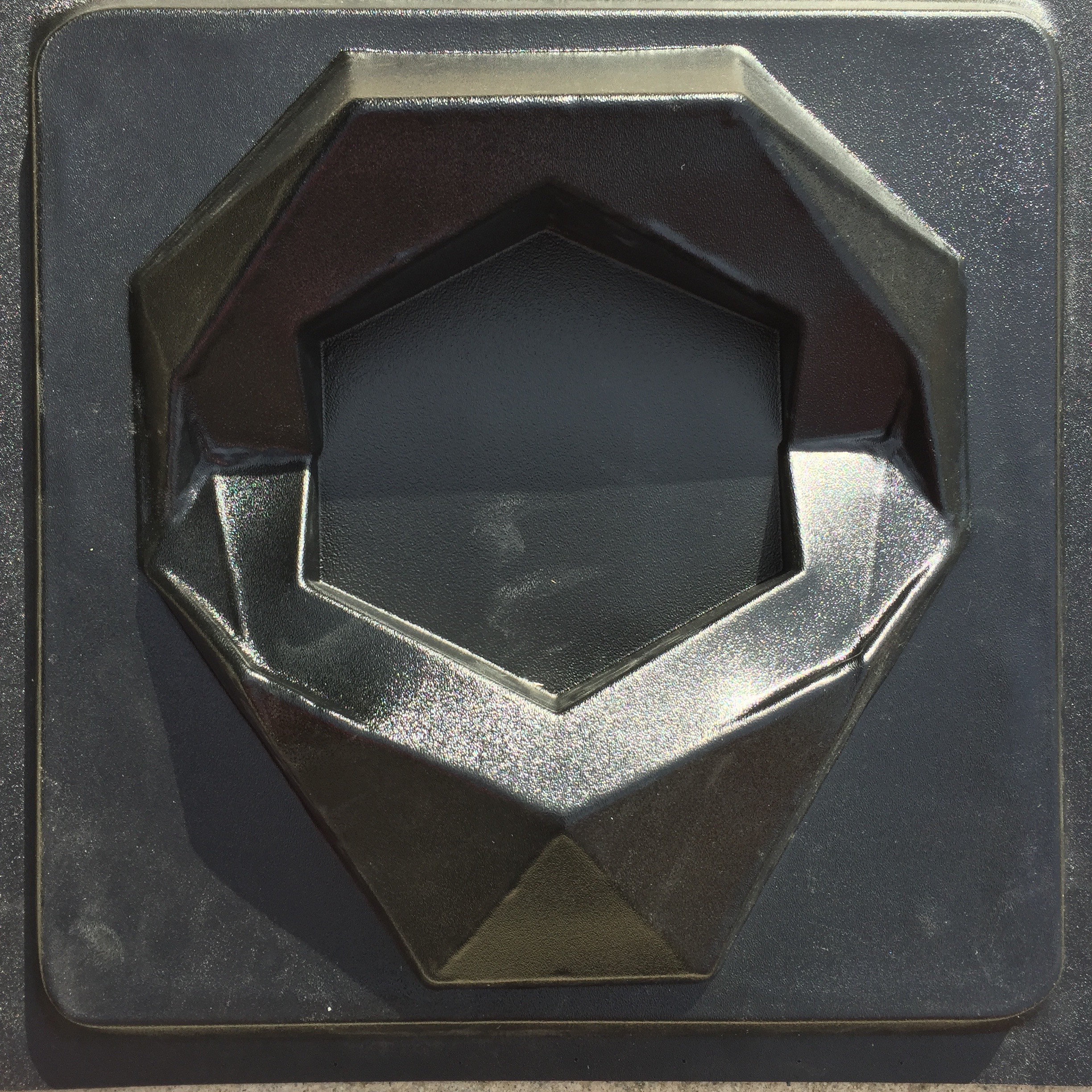
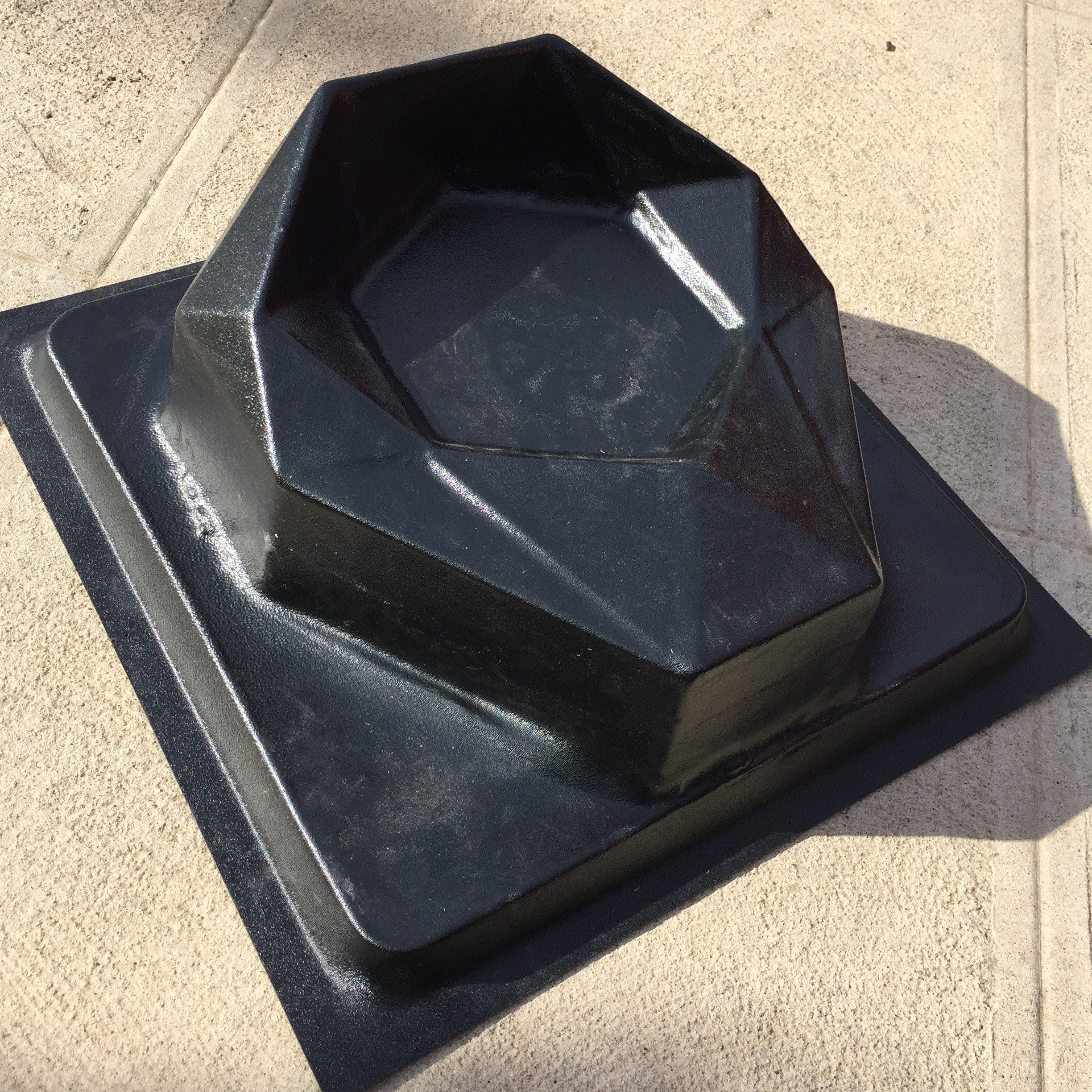
Now solid and smooth, it was time to send the bucks off to be vacuum formed!
![]()
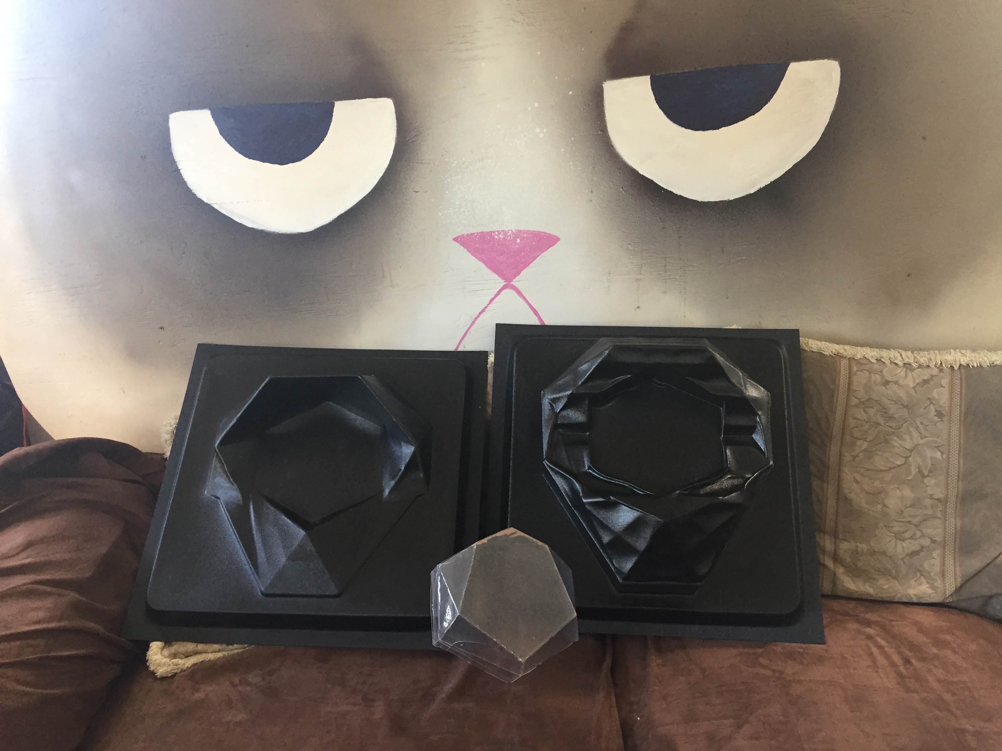
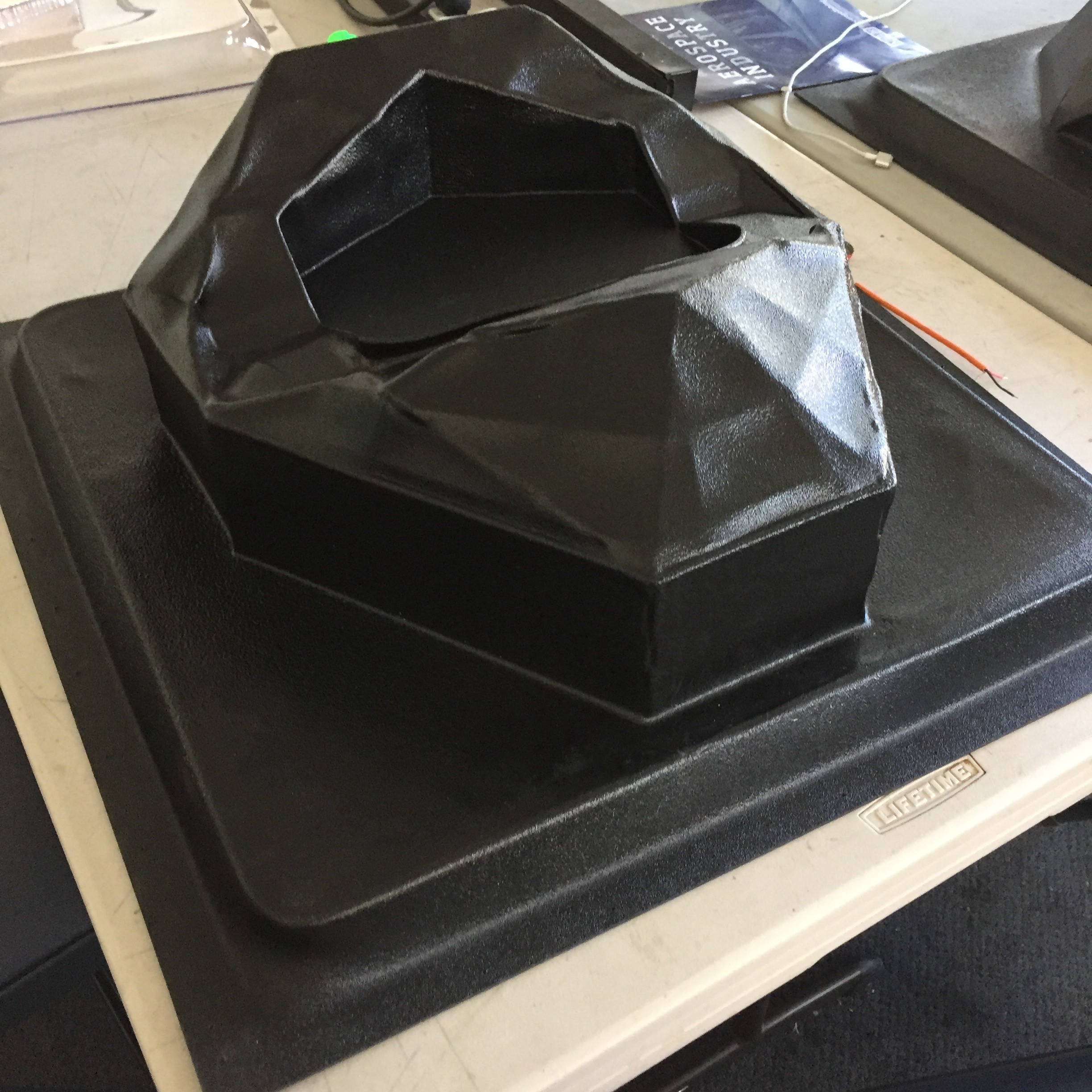
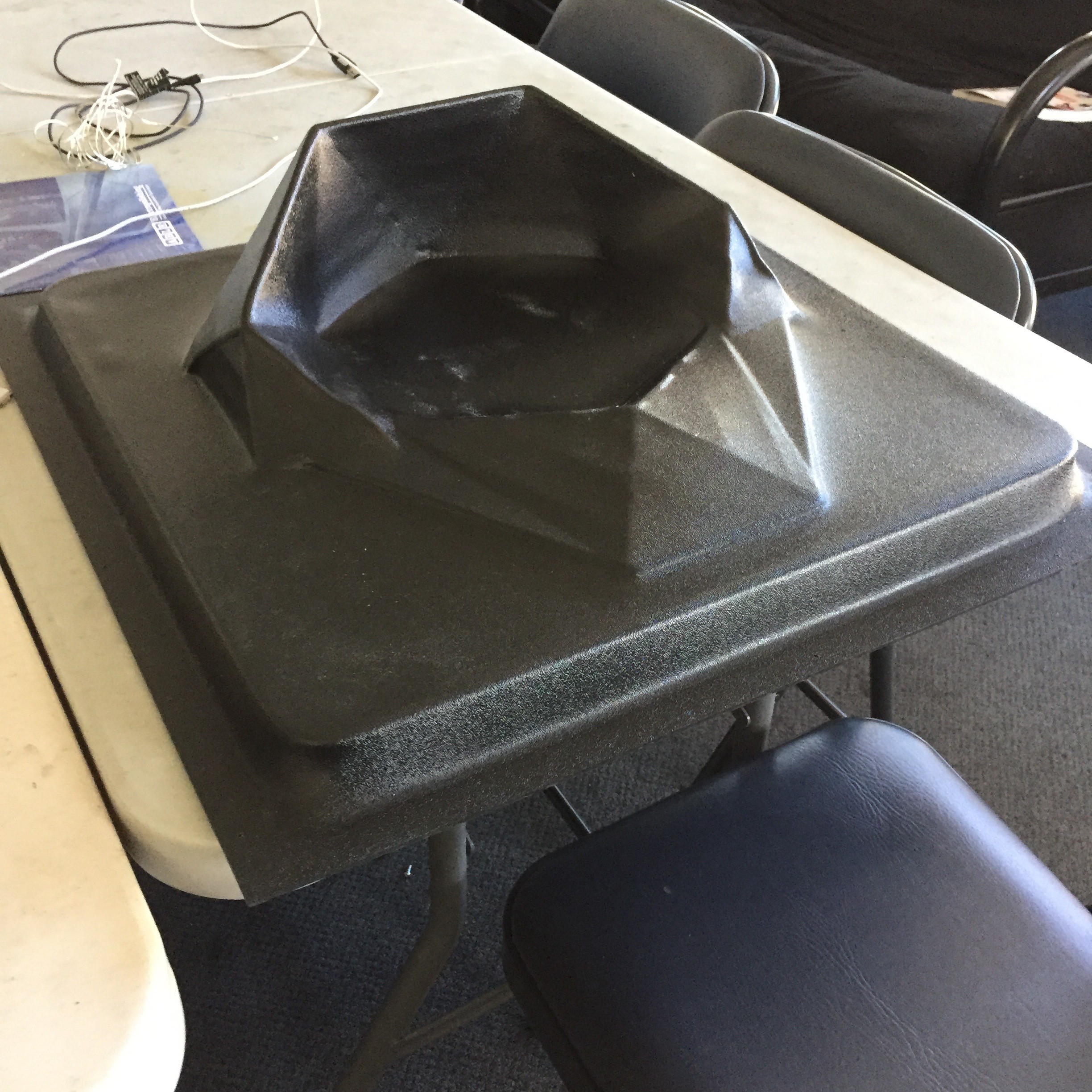
The results!
![]()
![]()
![]()
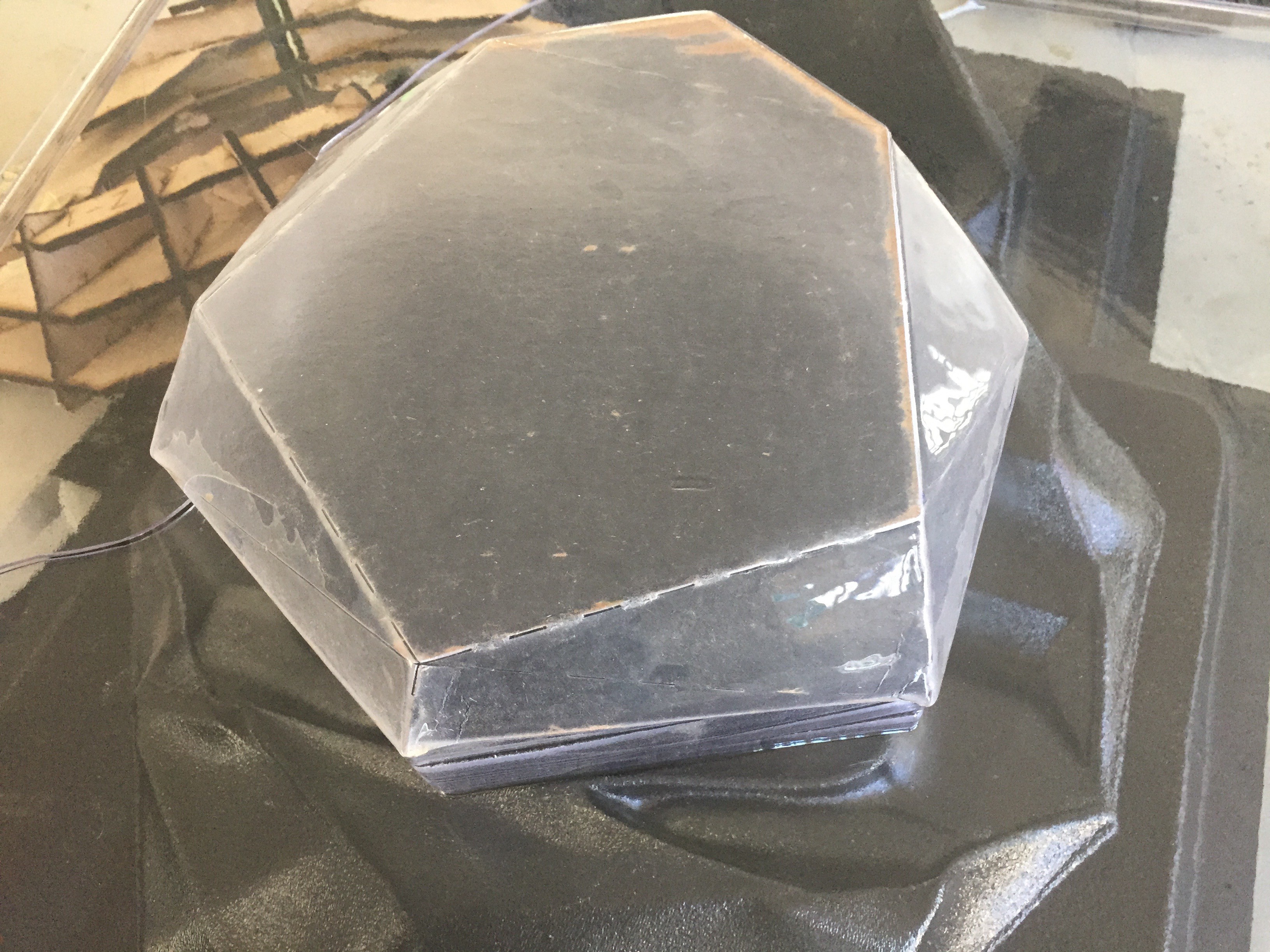
It was mostly a success. A few things are left to perfect, but we should be in a good place to start moving on shell production fairly quickly now. I'll need to build an even more solid set of production bucks than the glued together MDF, so I may try to rotocast some positives from these thin plastic pieces.
There's still a ton left to do, but these are big steps towards scaling the project in the coming year.
-
Shell Games
10/21/2016 at 19:33 • 0 commentsI've been away the past couple of weeks for a whirlwind of travel and partnership development, and finally have a moment to catch my breath and give everyone an update.
Last week I was in Austin presenting Perceptoscope as part of SXSW Eco's Place by Design. It was an amazing experience hanging out with a ton of other innovative artists, designers, and place-makers. So much happened over those few days that it's difficult to give a quick update, but a lot of exciting opportunities are coming together that will really get this project out in front of people around the city and the country. As more firms up I'll be sure to share here, and my presentation should be going up online in the next couple of weeks.
Speaking of exciting opportunities for the project, Perceptoscope is one of the finalists in the PLAY category for LA2050. If you have a moment to spare, please vote for the project and help us bring Scopes to exciting locations around Los Angeles. Voting ends October 25th, so spread the word!
In terms of fabrication milestones, vacuum forming my current shell mold proved to be less than successful, but I learned a lot about how to improve the process going forward. First the results!
![]()
The laser cut ribbing definitely held up ok, but unfortunately I didn't use a thick enough material outside the ribbing to survive the extreme suction of vacuum forming. You can see how the outer shell bucked a deformed a bunch, especially on the front of the shell.
![]()
![]()
The clear window came out of the process OK, but I'll need to make sure the surfaces are super smooth if I want them to maintain optical clarity.
![]()
I was in such a rush to get something done that I didn't build proper drafting into the molds either. This made it pretty difficult to remove the positive from the shell piece after it had been pulled. It's probably going to take me a bit of time next week to get the positive just right, and then I'll work towards a new set of shell pieces.
Though it came out of the process a bit janky, the more important thing to recognize is this process will absolutely work for producing the shells quickly and cheaply once I've got the mold issues sorted out. Even when something doesn't work as you'd hoped, lessons are learned and you just have to keep moving forward.
-
Form and Function
10/03/2016 at 22:38 • 0 commentsSupplyFrame recently released a new episode of Open Source following Perceptoscope. You can check it out above. They've also been documenting all our time at the lab via their podcast Inside the DesignLab which is definitely worth a listen. I'm interviewed in the first and third episodes.Last week we made big progress on the main body of the shell positive, but I still needed to fabricate 5 more elements of its shape before we could take this positive to be vacuum formed.
Since 2D operations were previously successful on the ShopBot, I figured it was time to try for a 3D milling. We'd start with the transparent Iris that the optics look out through. Using Vcarve Pro, we broke the 3D object into multiple slices and generated all the different tool-paths required to give us the proper angles along the slice edges.![]()
![]()
![]()
It looked a little rough when I took it off the bed, but fortunately its faceted shape meant I could clean it up pretty easily on the belt sander.
![]()
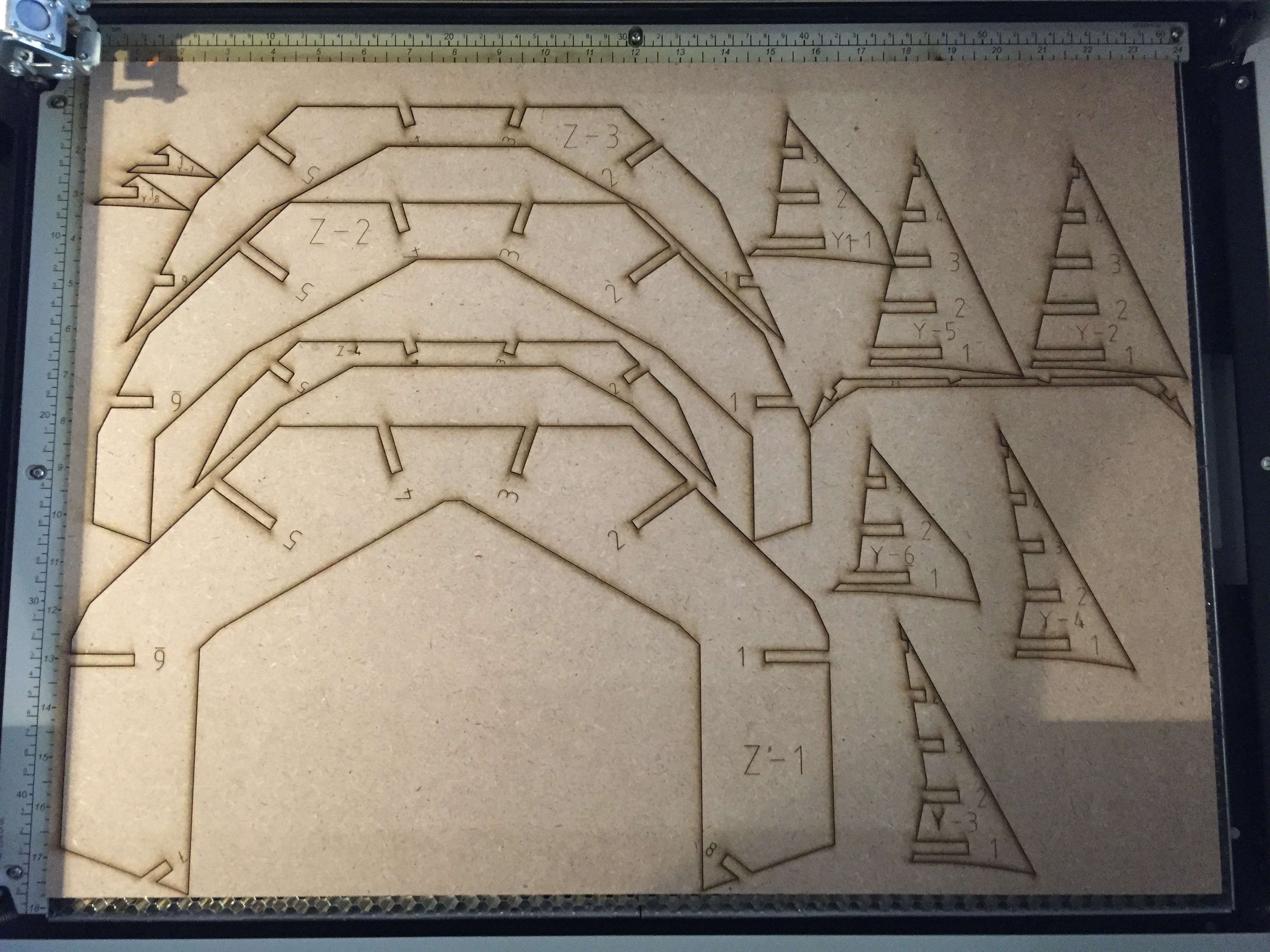
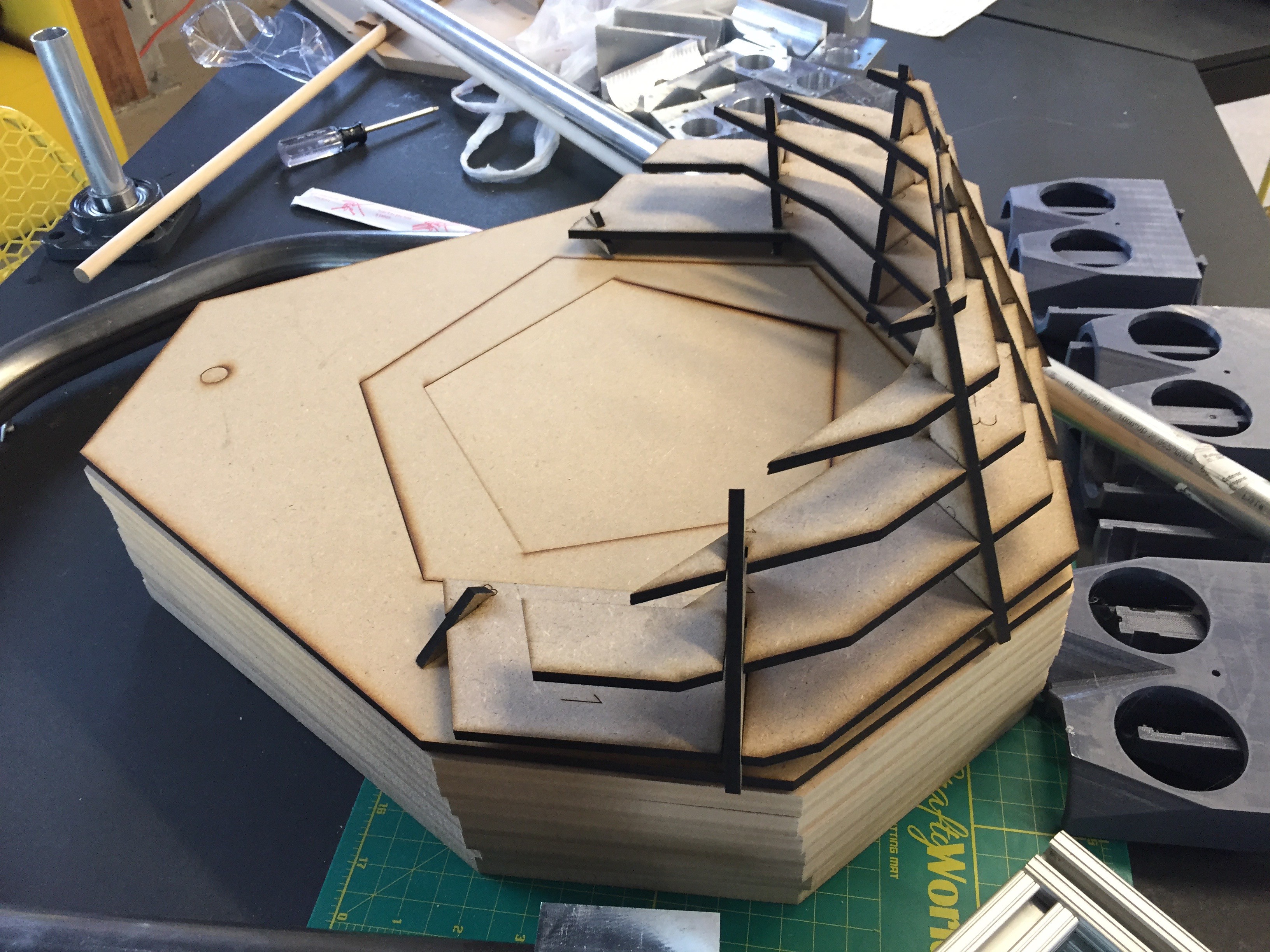
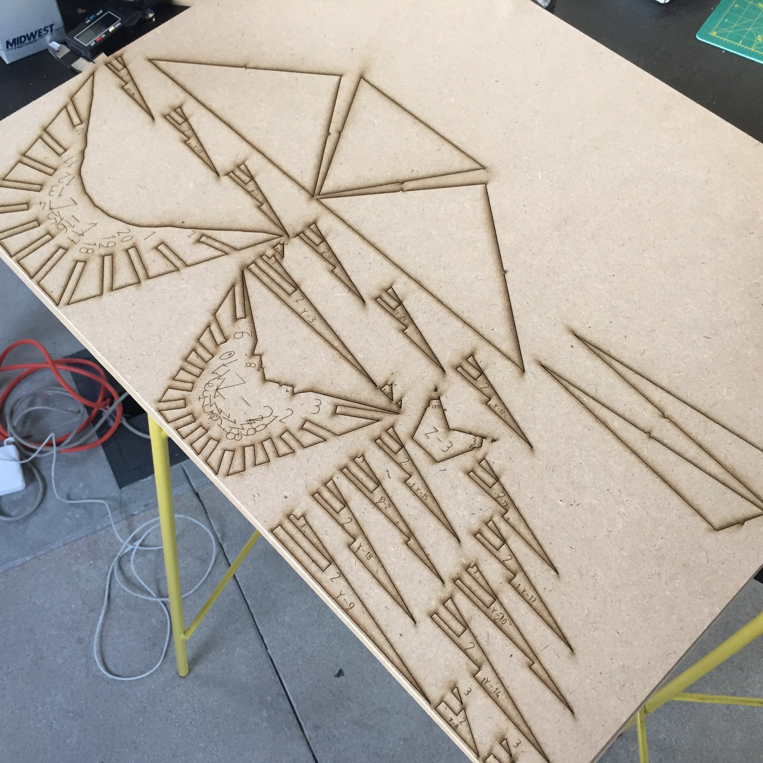
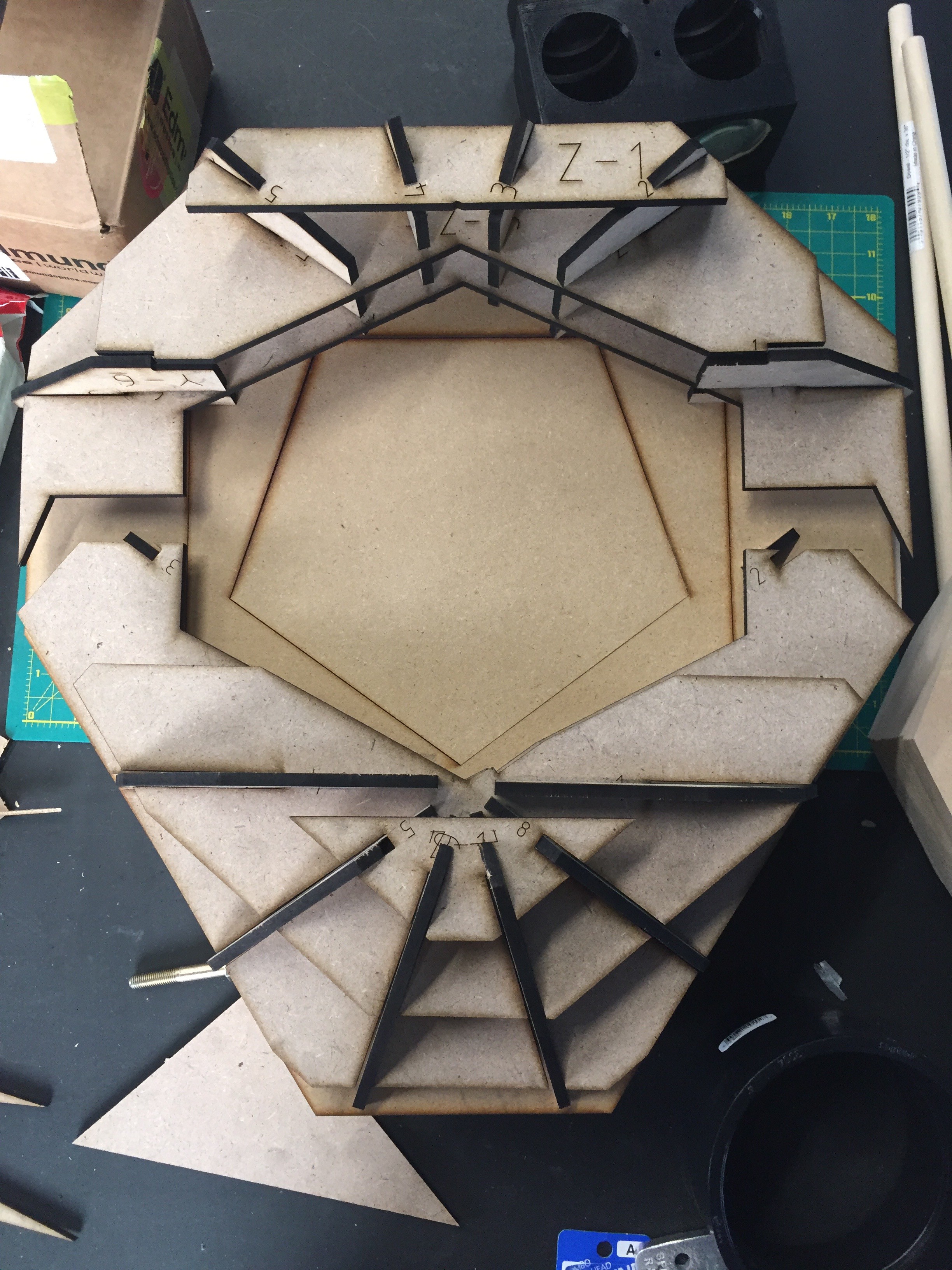
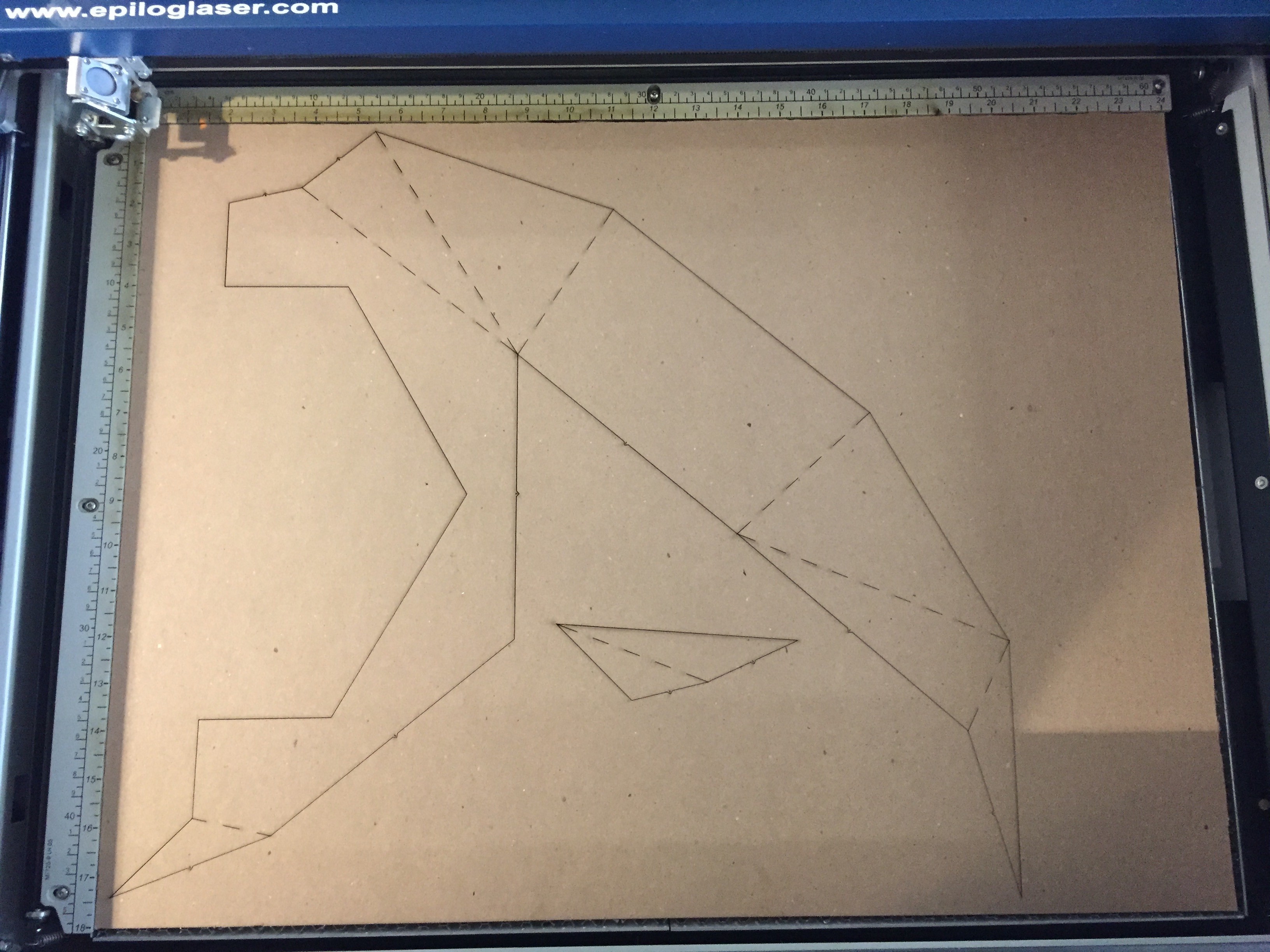
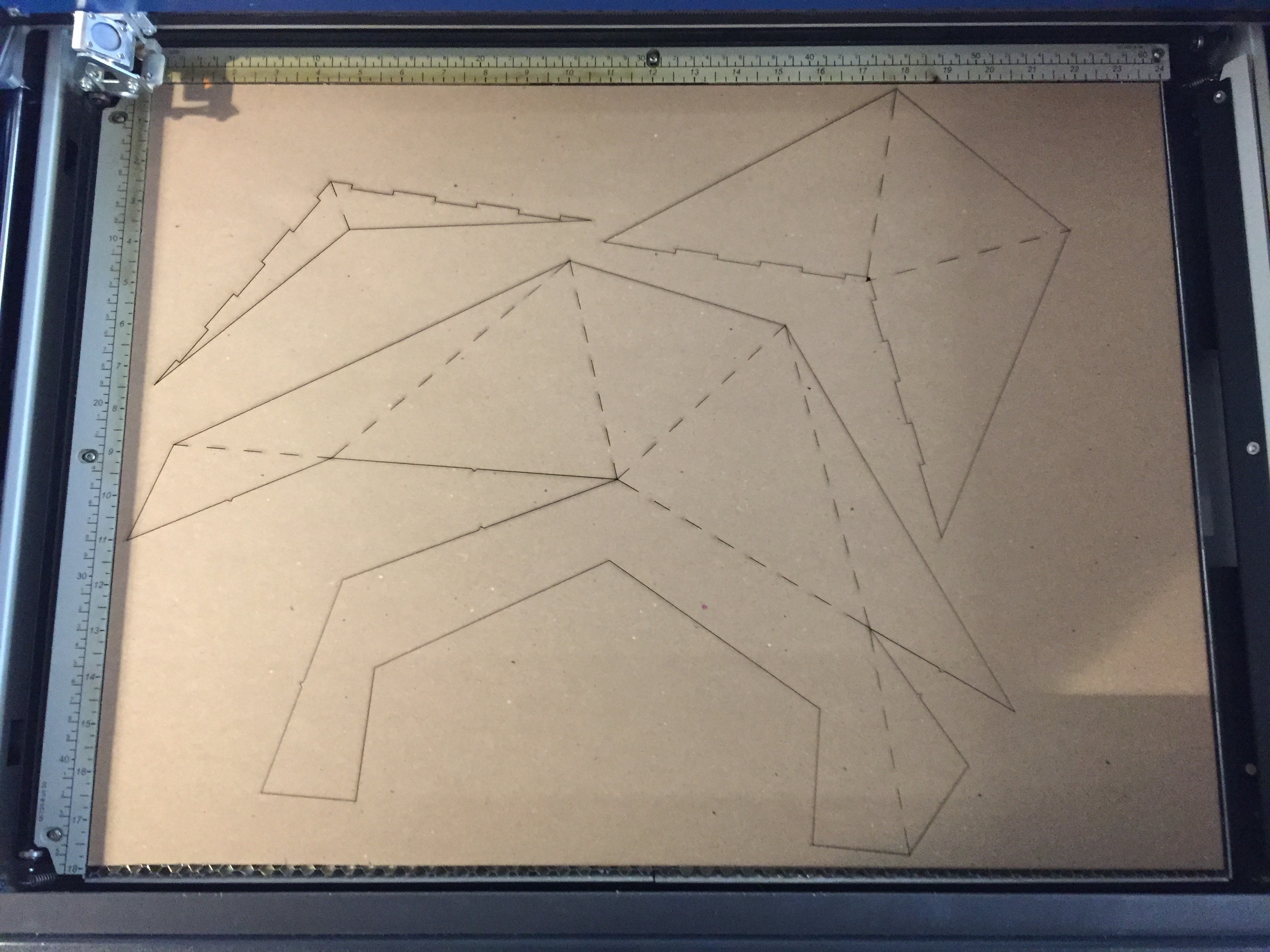
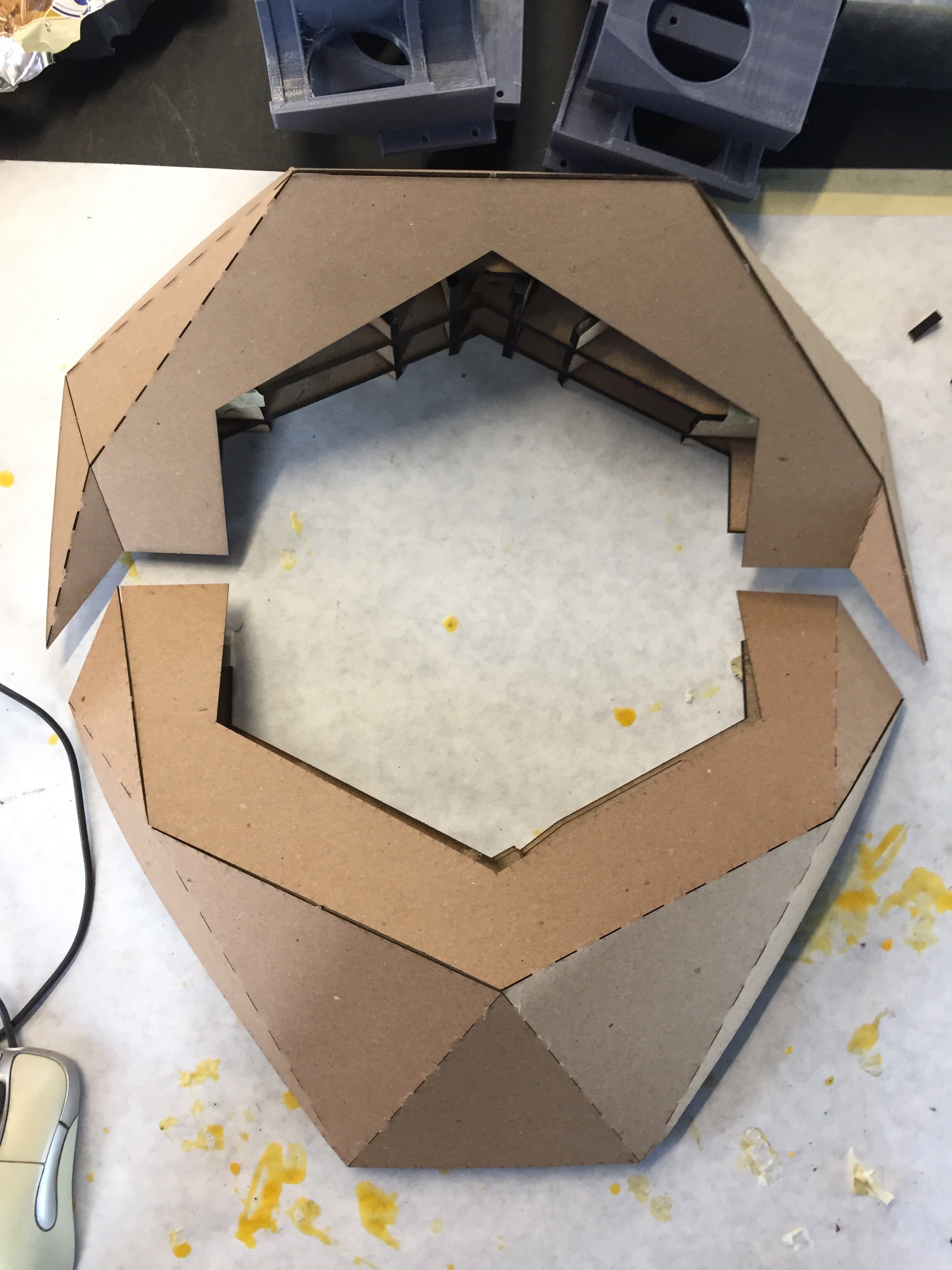
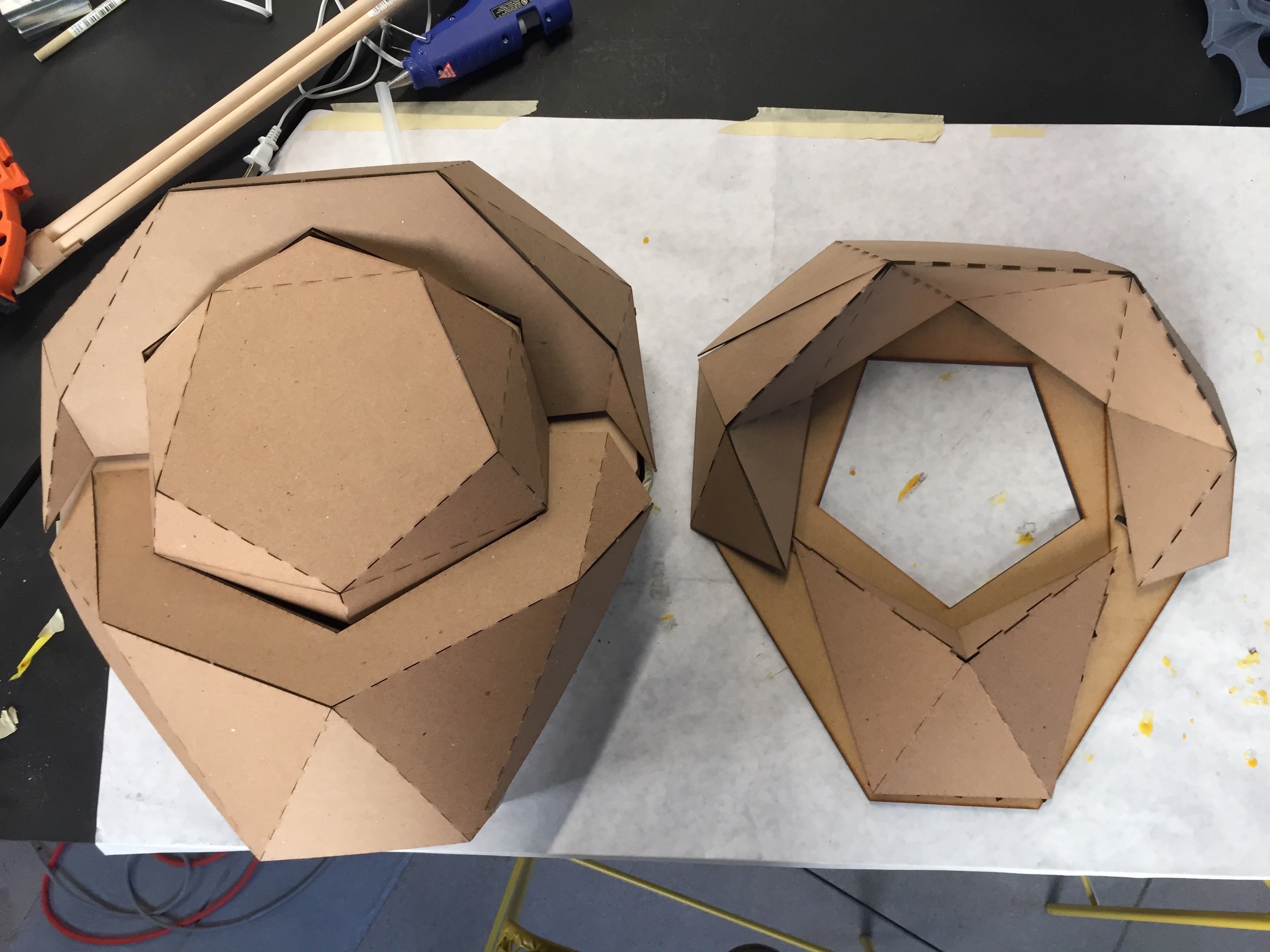
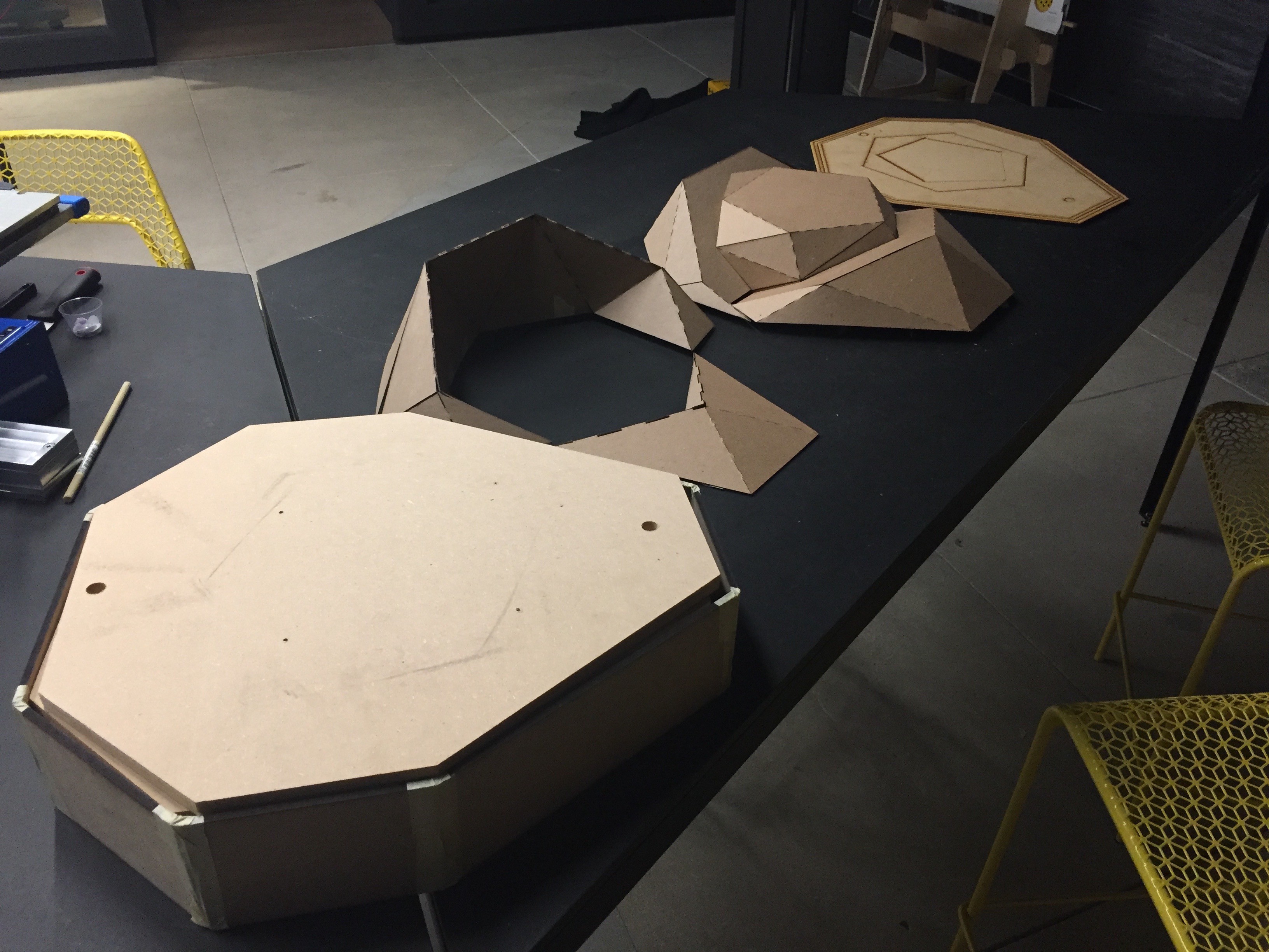
The rest of the pieces are a bit more complicated, so I wanted to experiment with a different approach. Desiring speed and efficiency, I gravitated towards the laser cutter. The idea is to laser cut an internal ribbing for each piece out of MDF, and then shell it with laser cut card stock. 123D Make proved to be an amazing tool for generating the forms.
![]()
![]()
![]()
![]()
The ribbings turned out looking quite beautiful. I glued them up to give them strength, and left them to dry overnight.
![]()
I also found some time to sneak over to CRASH Space for a bit so I could build out the yoke assembly with the help of their drill press.
![]()
![]()
![]()
![]()
It's feeling both strong an balanced. I'm excited to finally start mounting components.
Back at the Lab, I laser cut the shells of all the forms out of card stock, and finished up the remaining elements.
![]()
![]()
![]()
![]()
![]()
With all the pieces in place it was finally time to bring the shell positive to the vacuum former. In fact, I just dropped it off this morning at a local shop. I was met with a bit of skepticism that it would work, and can already see some areas to be improved from a manufacturing perspective before production. Either way, I left them to be pulled as an experiment. Fingers crossed this was an effective technique.
-
Almost there.
09/26/2016 at 18:43 • 2 commentsNow that we've got a good sense of the internal layout, the big focus of this past week has been getting all the pieces in together to make the positive of the shell for vacuum forming.
![]()
It took of lot of CAD work to get things feeling and fitting just right, and I never could have anticipated all the challenges ahead with actually making it full size. To start, I 3D printed another scale model. This is the model we'll use when producing the final mold.
![]()
![]()
![]()
It got a little melty on the printer, particularly over the shroud that will surround the eye-piece area, but I'm really liking how this turned out.
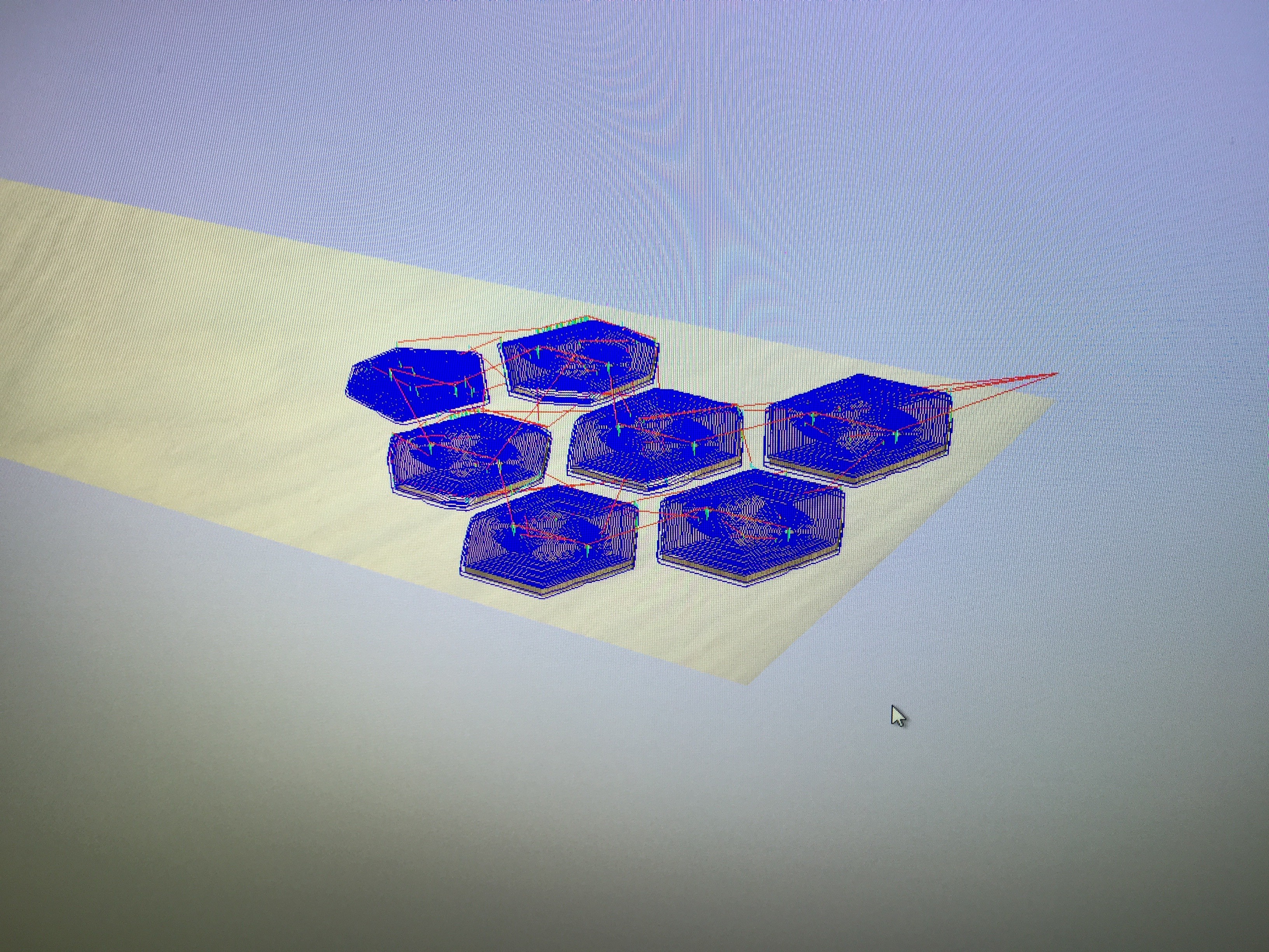
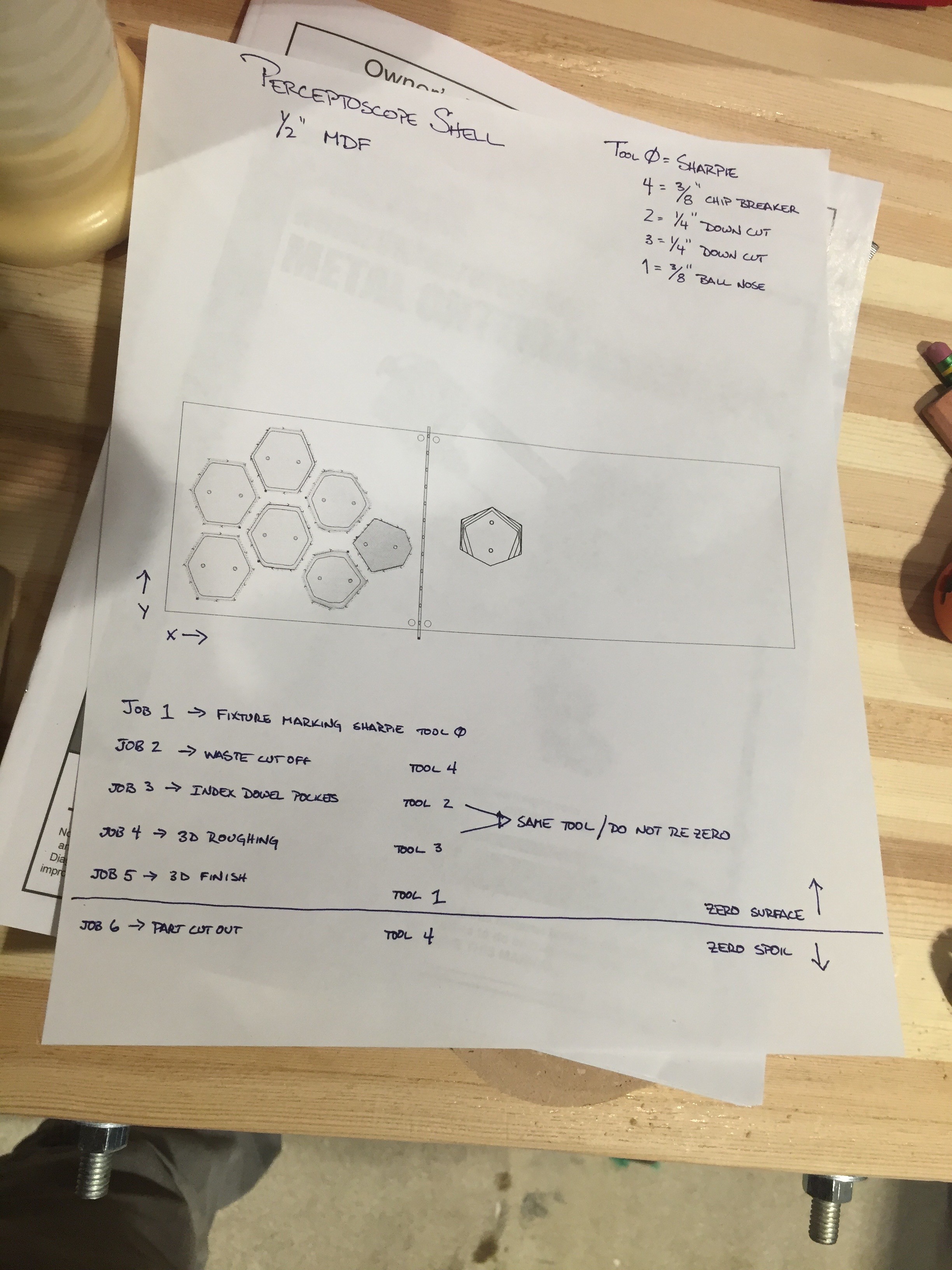
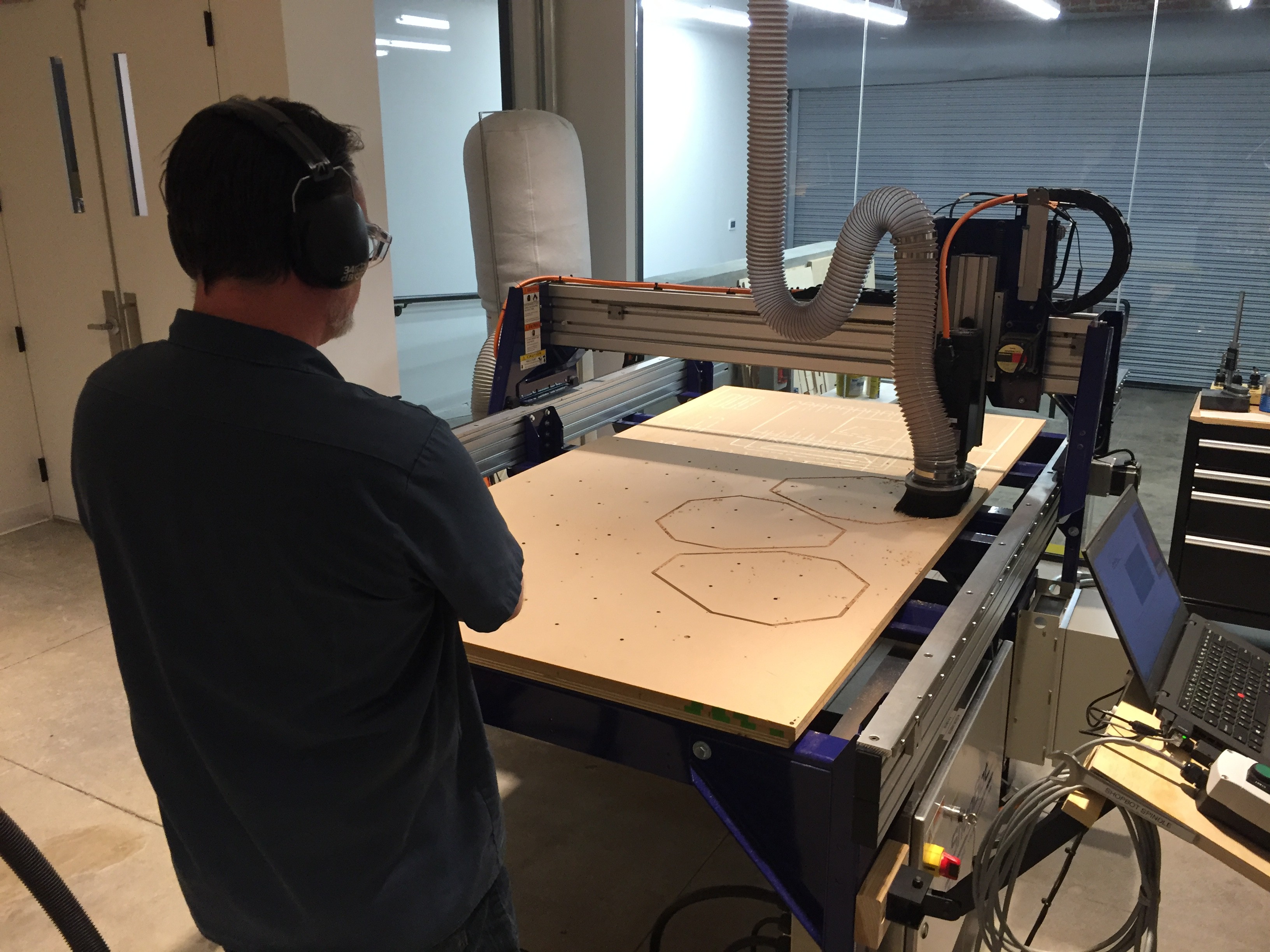
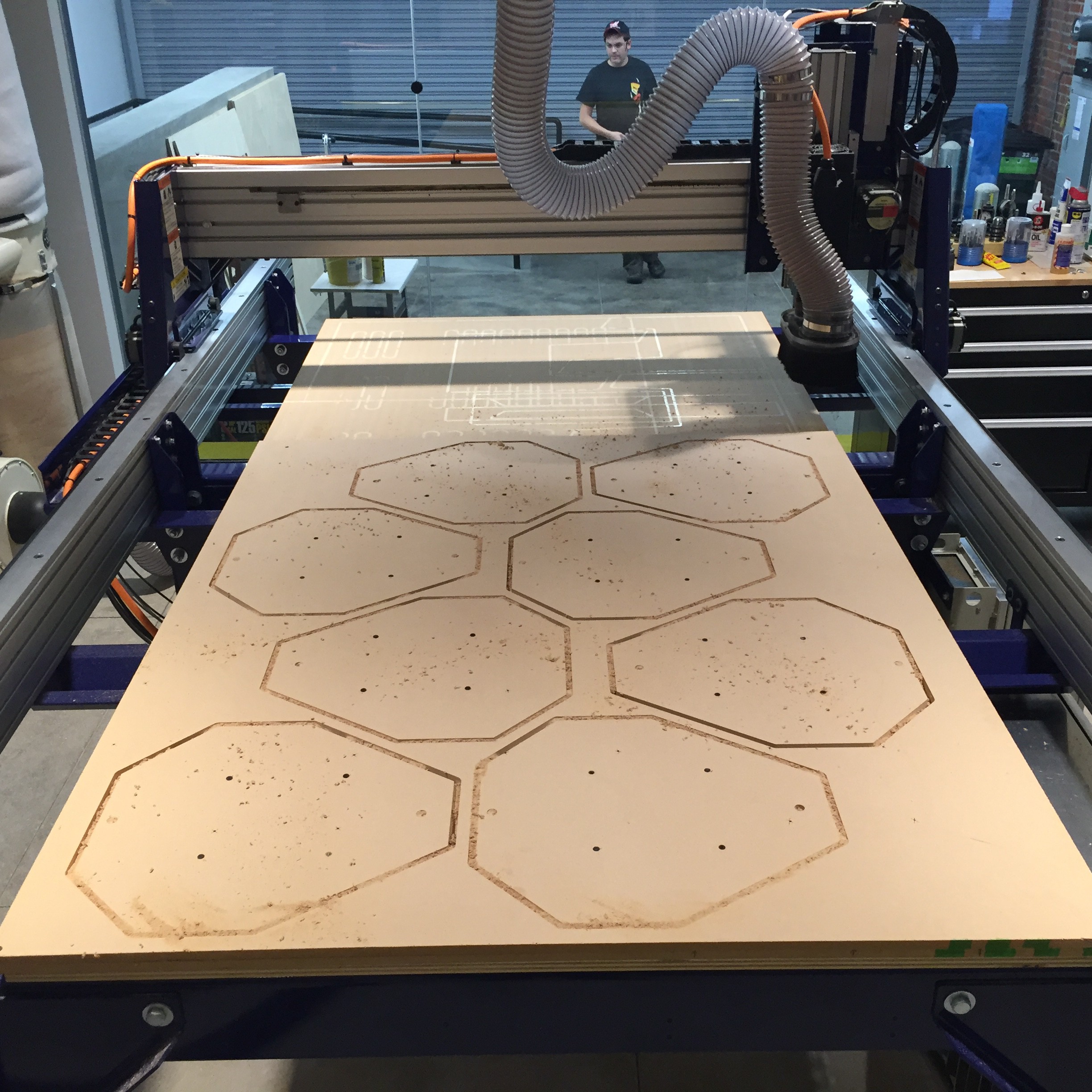
Milling it on the ShopBot out of MDF has proven to be its own set of challenges. For one, I was trying to slice the model for 3D carving but with all the different tool paths required the ShopBot would have had to run for 4 days straight. Clearly there's a better way to go.
I started by manually slicing the model into easier to manufacture individual components. There are six parts total -- one main large body that's pretty easy to produce with 2D operations, and then another set of accoutrements that help the end users understand functional issues like front and back, or help shade them as they use it.
![]()
These next three components are on the side opposite of the viewer's eyepiece, and the round geode component will be made out of a semitransparent material so the binoculars can see through it.
![]()
![]()
![]()
These next two piece are on the eye-piece side of the Scope, and hopefully will be inviting enough to pull a passerby to look through.
![]()
![]()
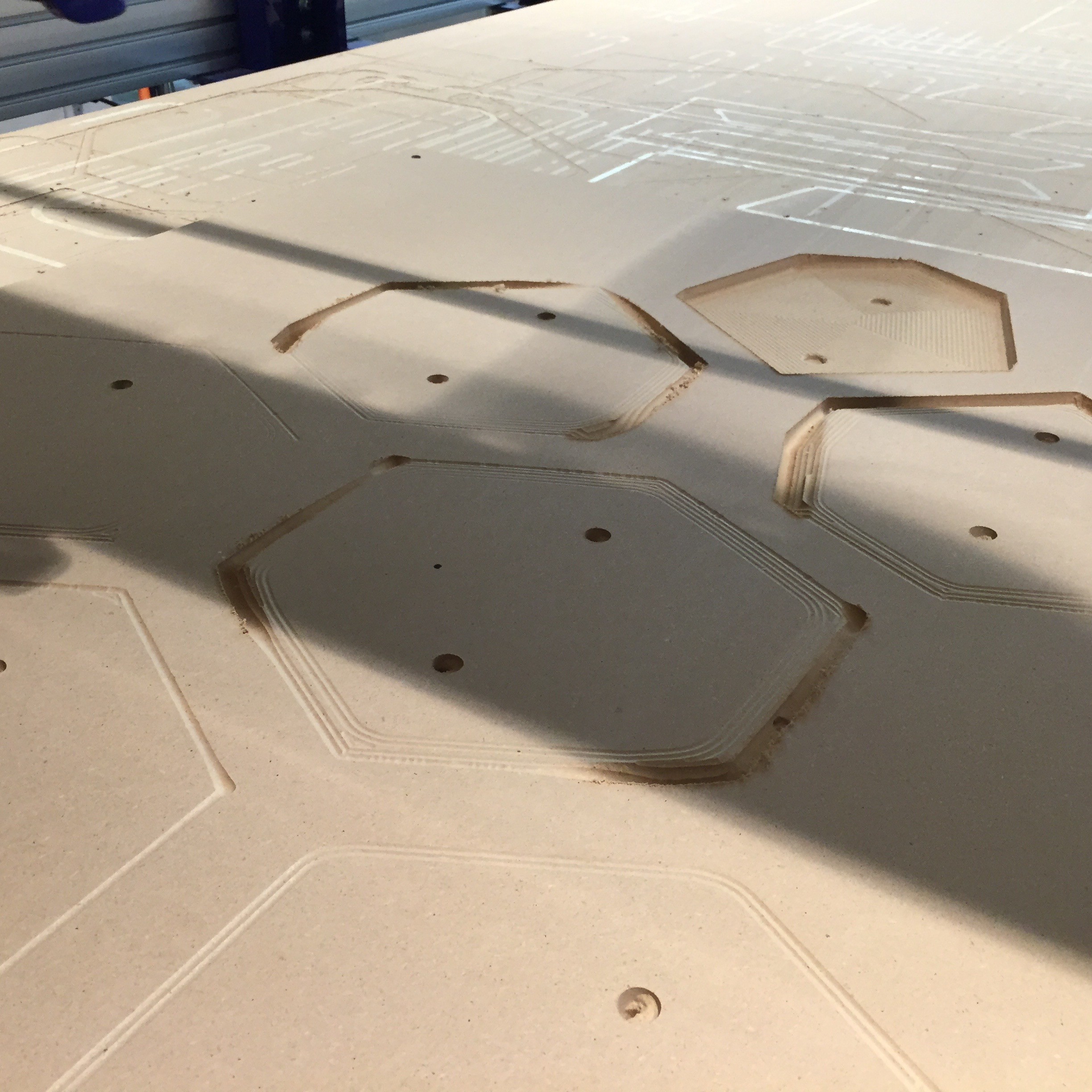
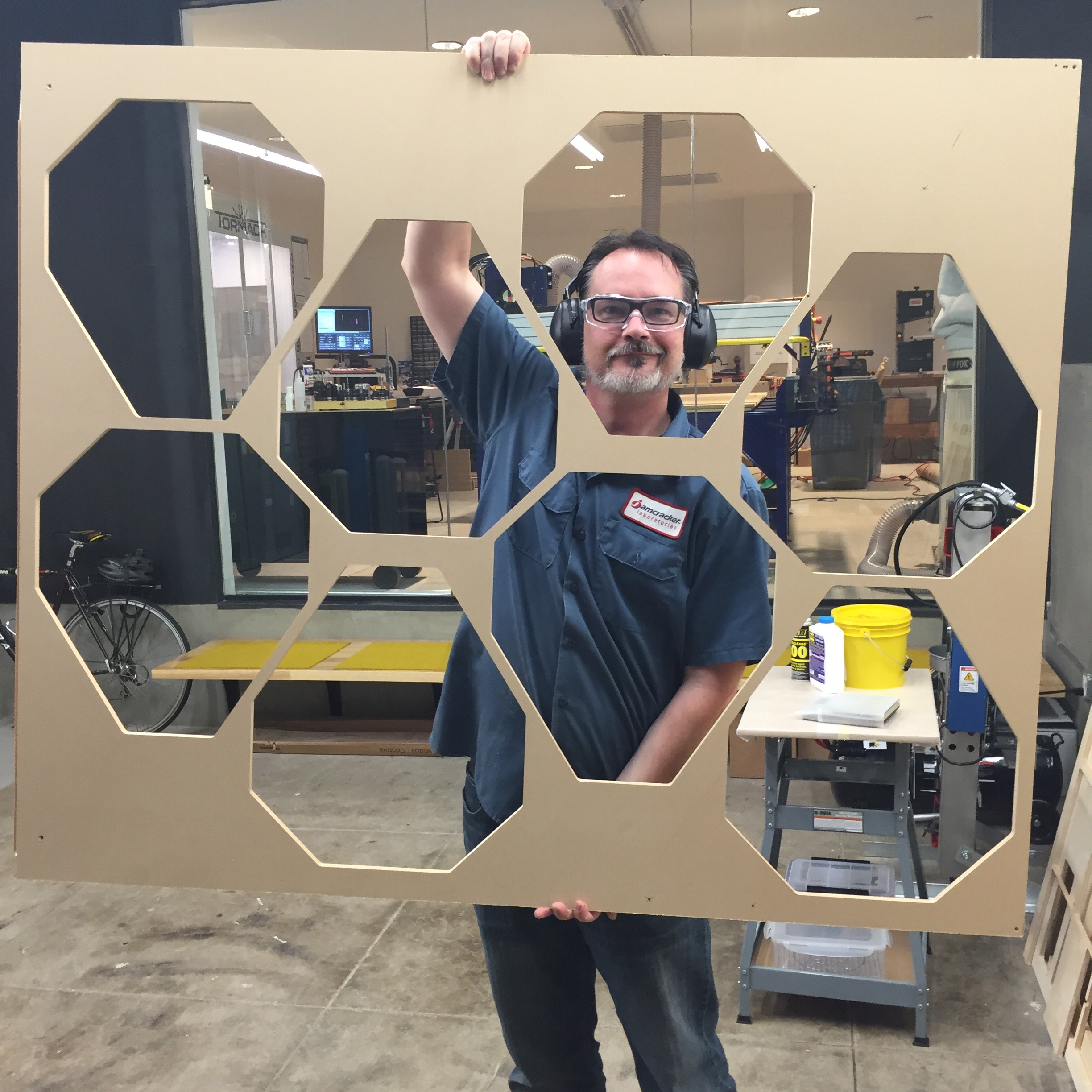
Dan and I were able to get the main body component milled out in slices of 1/2" MDF on the ShopBot towards the end of last week.
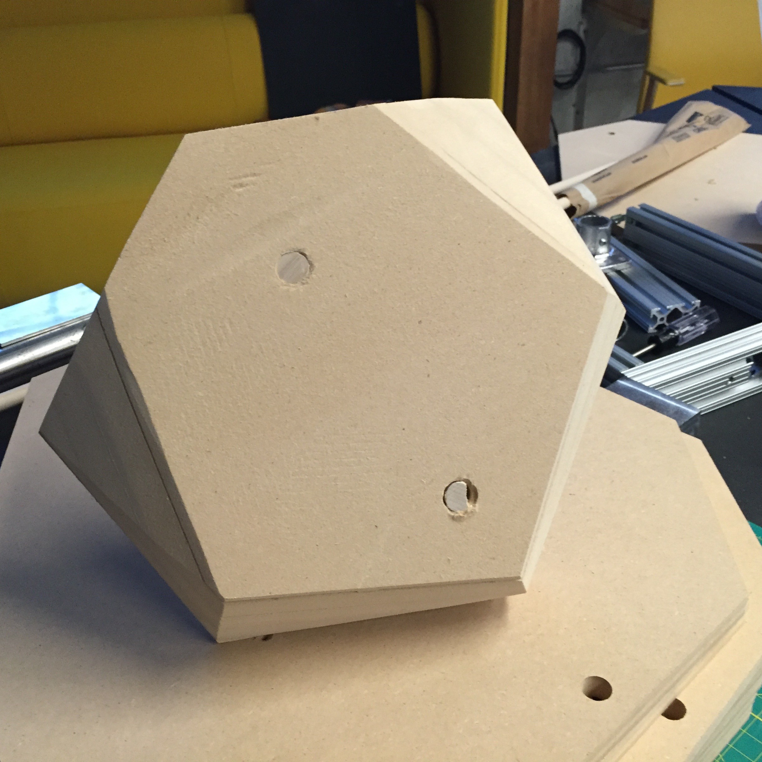
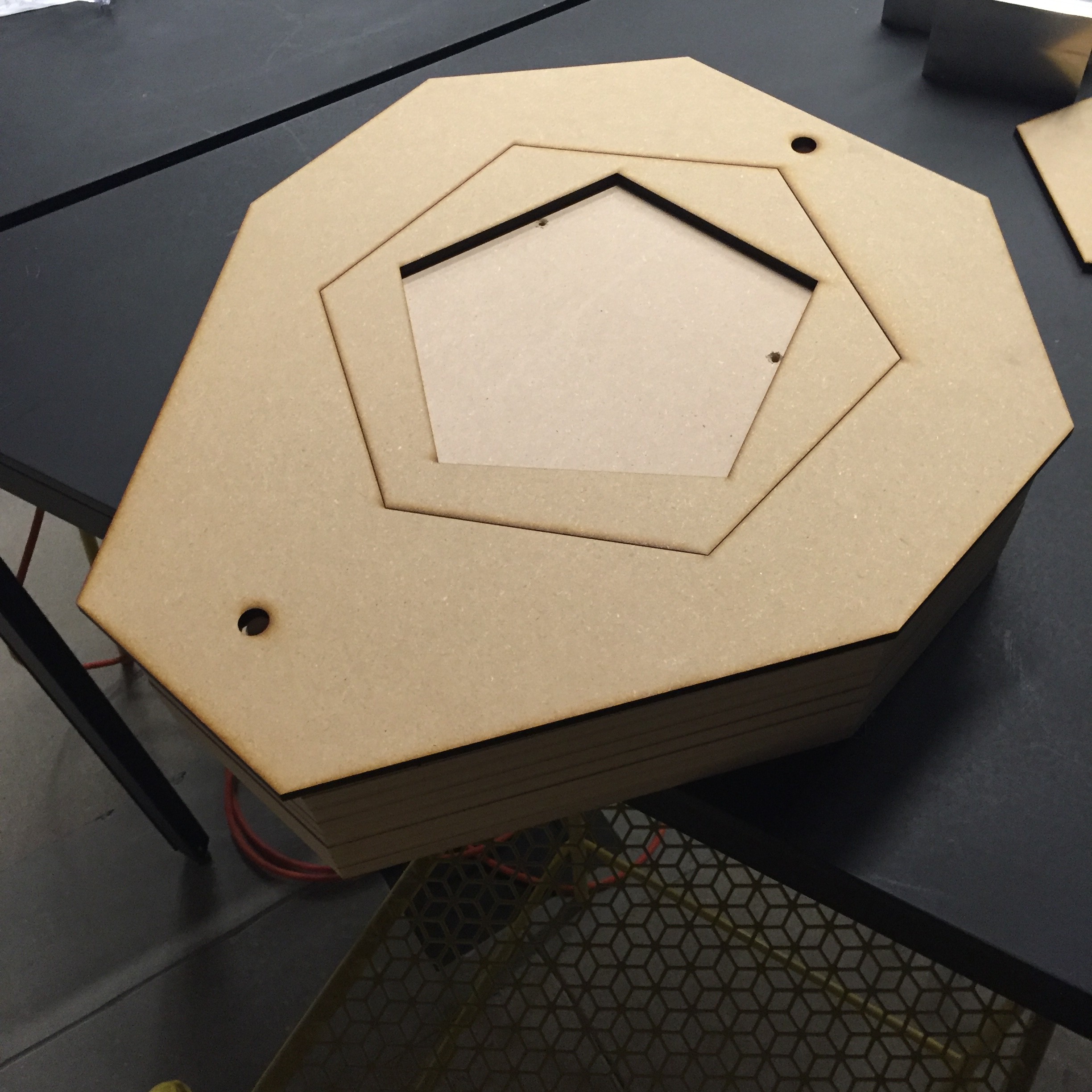
I also laser cut a panel out of 1/4" MDF to use as an adaptable faceplate for each side of the vacuum form pull. Thickness and physicality of the whole thing is looking just right.
In terms of there rest of the project, I made some progress on assembling the internal frame out of 80/20 T-Slot. We also finished up producing enough bearing blocks to make five new Scopes, and I came up with a cool design for my final optical housing.
![]()
![]()
![]()
![]()
With just a week left in the residency there's still a decent amount of things left to do, but at the very least I should be able to walk out of here ready to scale this project significantly.
-
Tailor Fit
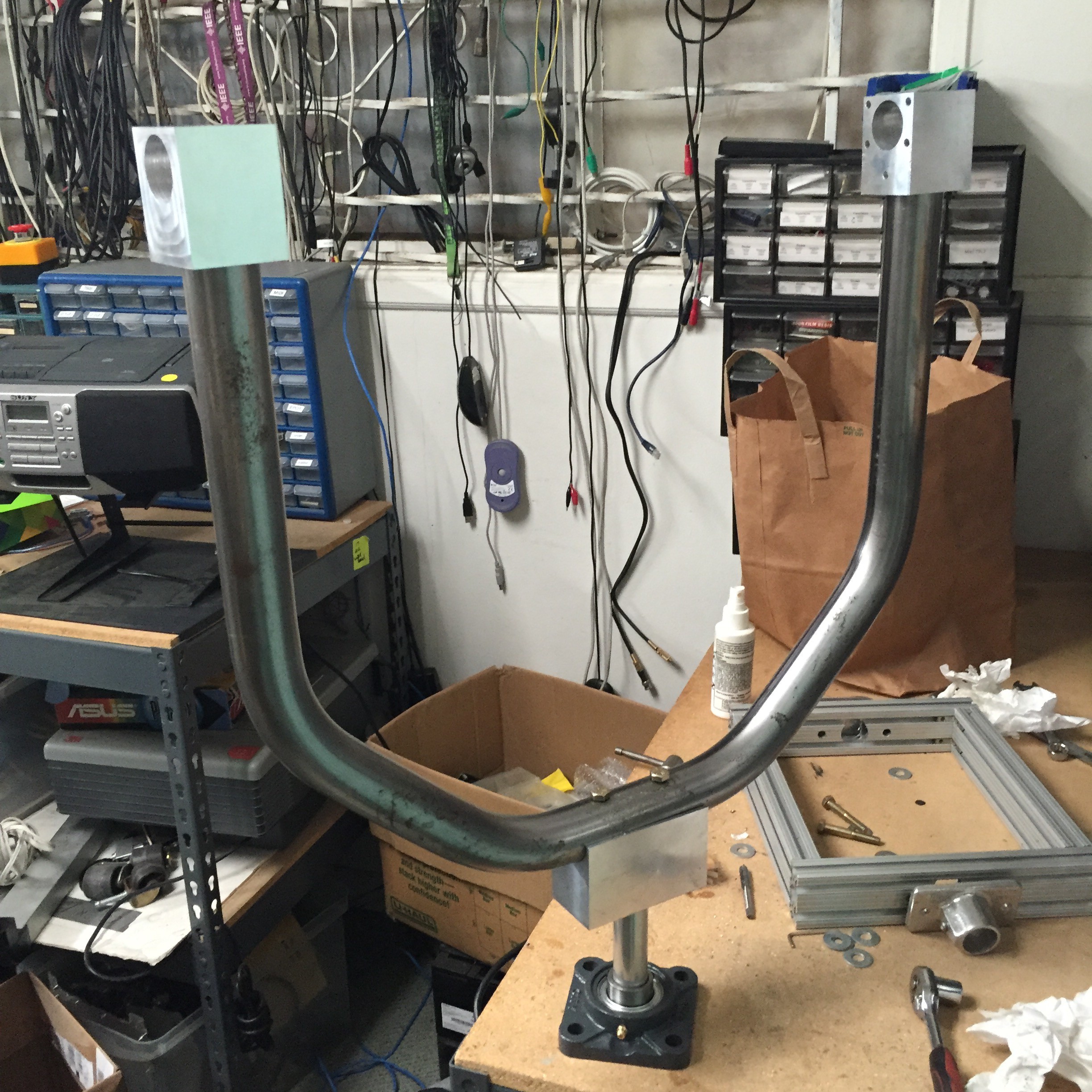
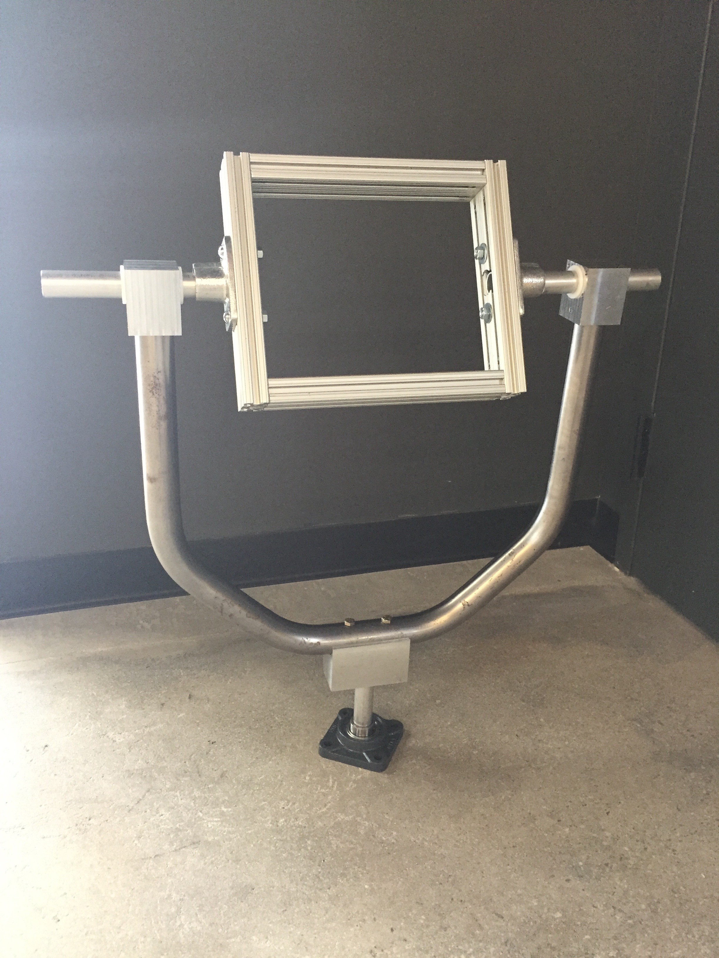
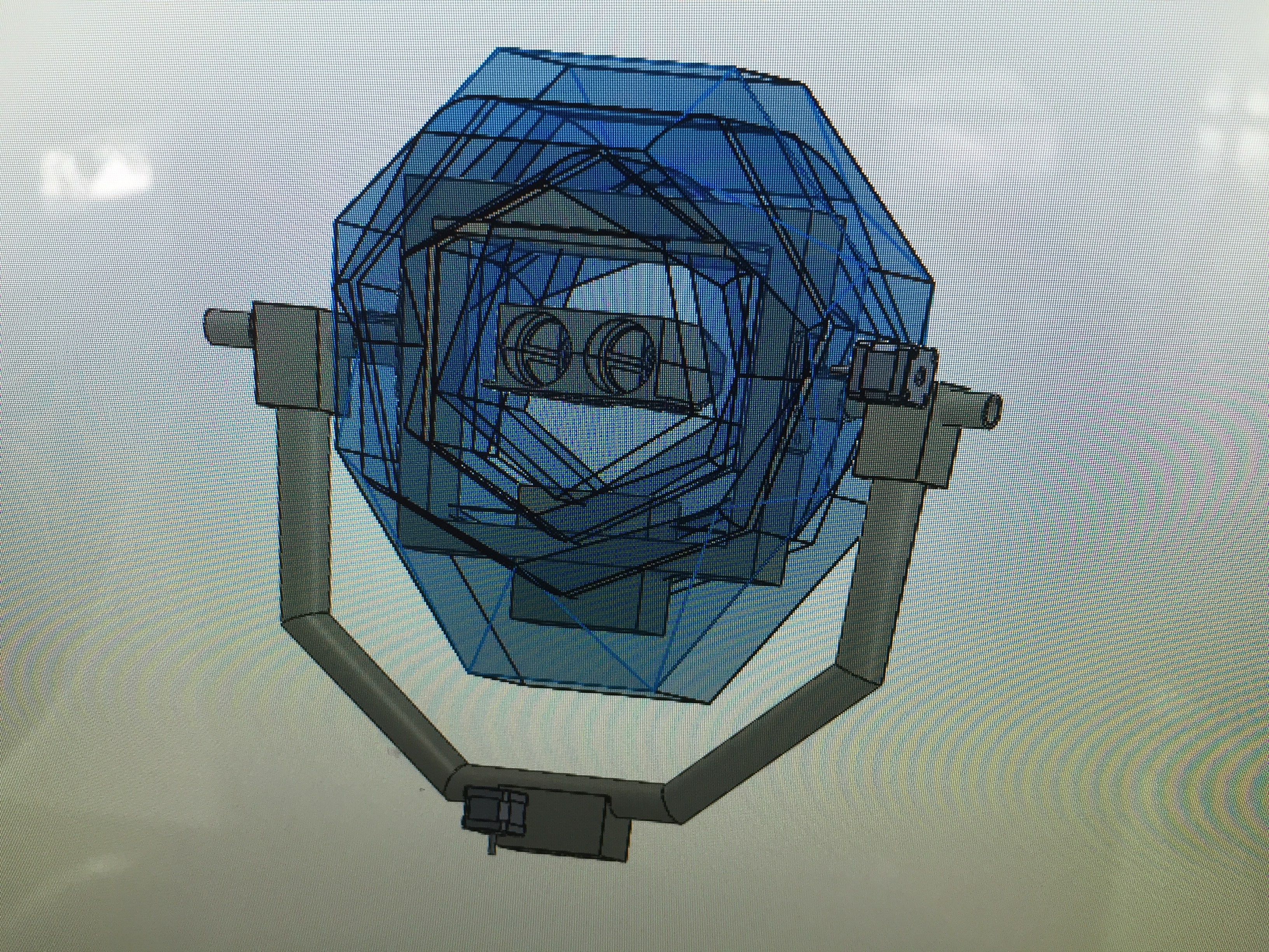
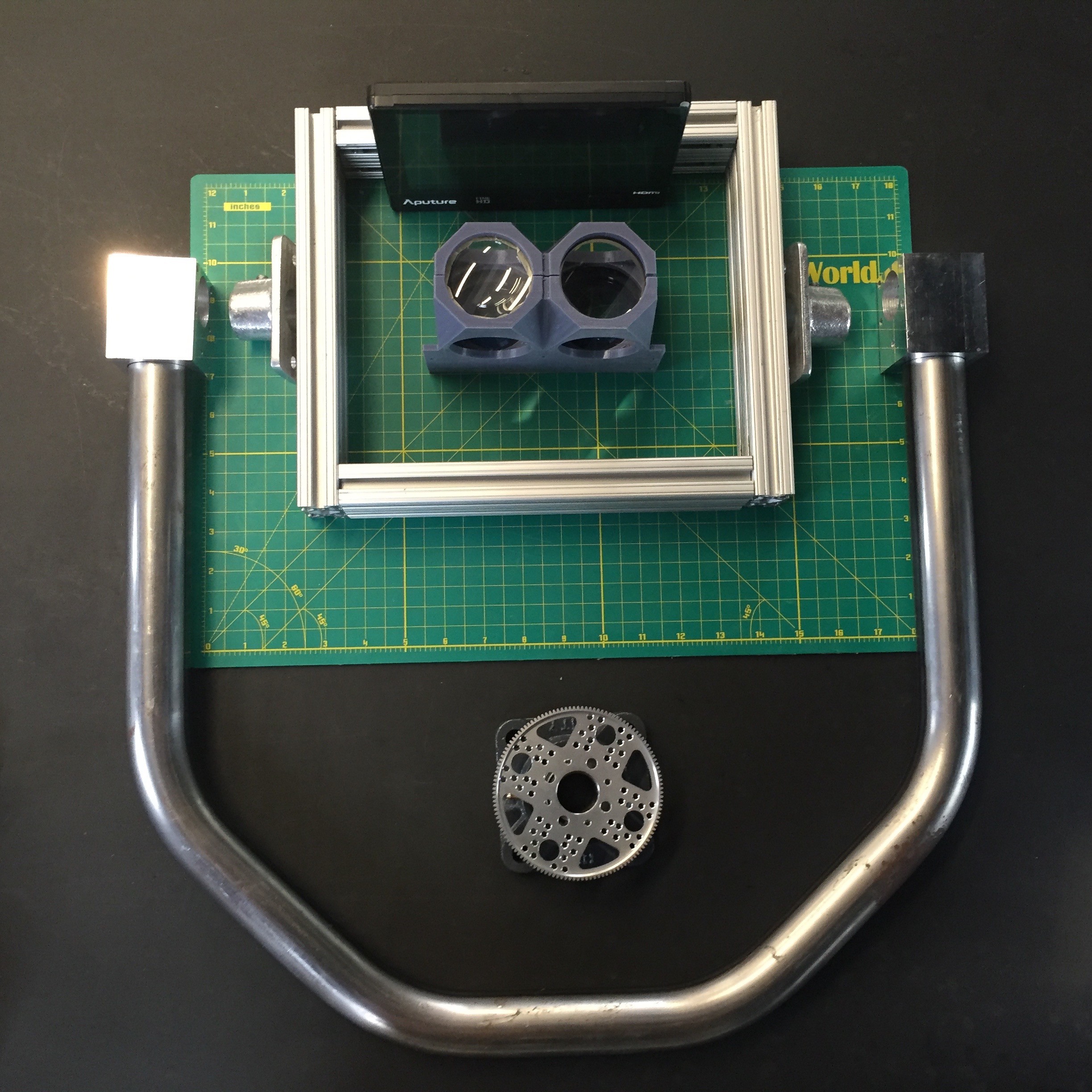
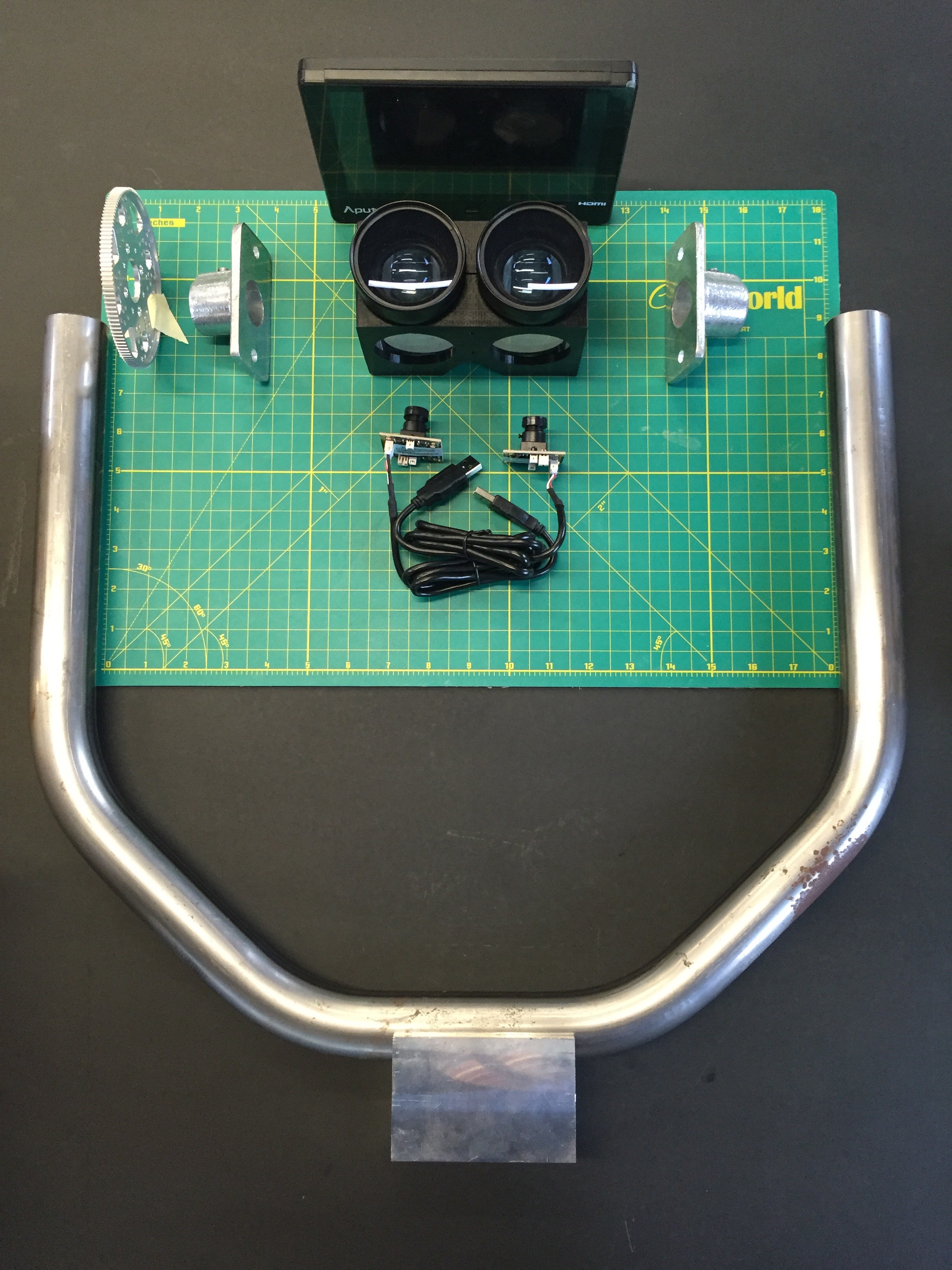
09/19/2016 at 18:38 • 0 commentsWith this final push towards assembly I started by doing a rough layout of components in the context of the yoke. It gives a good sense of how things will come together.
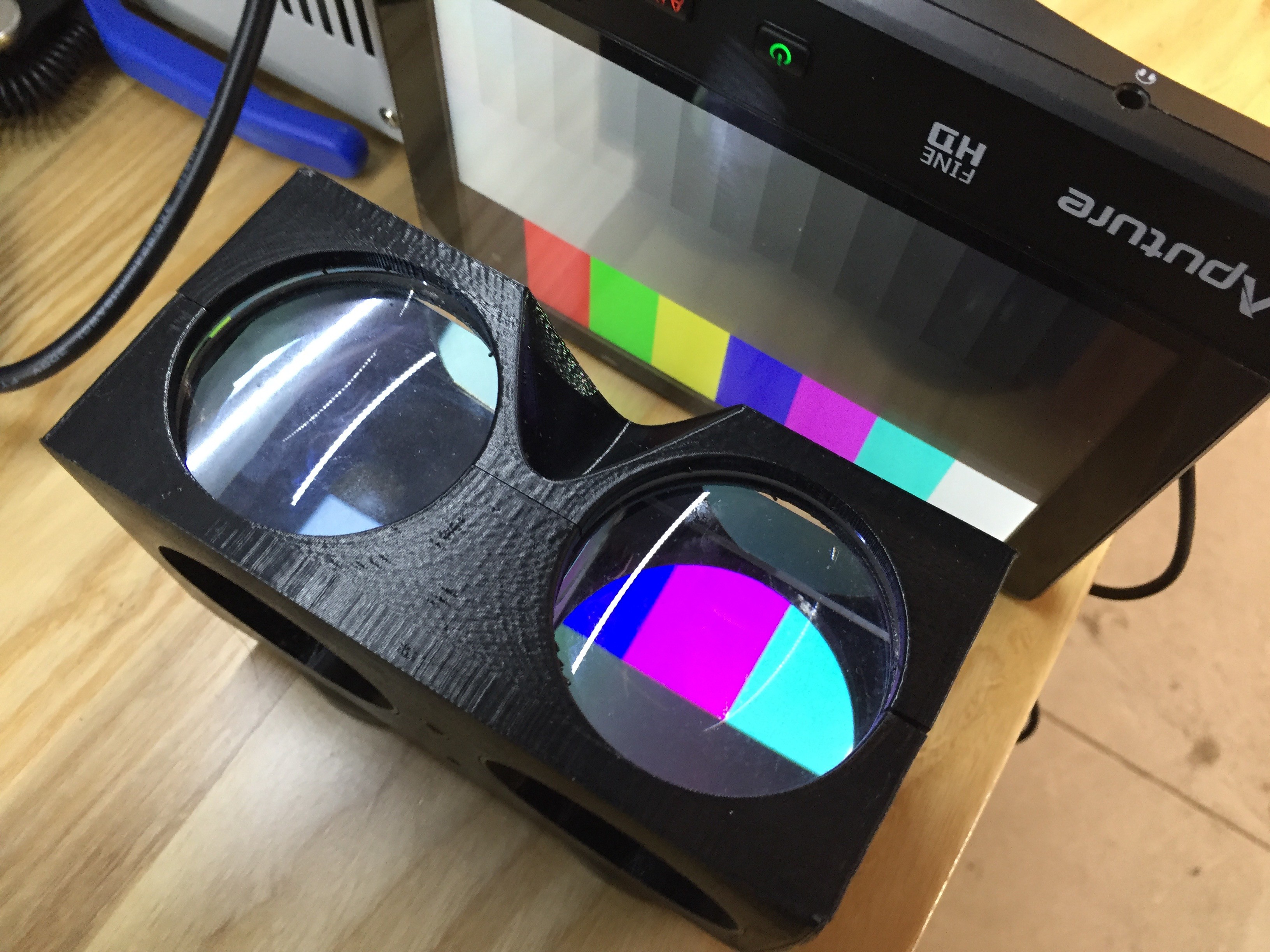
![]() One thing I wanted to make double sure of was that the distances between the screen and my optics were correctly calibrated for focus, so I powered up the screen with one of the tabletop power supplies and did a few tests.
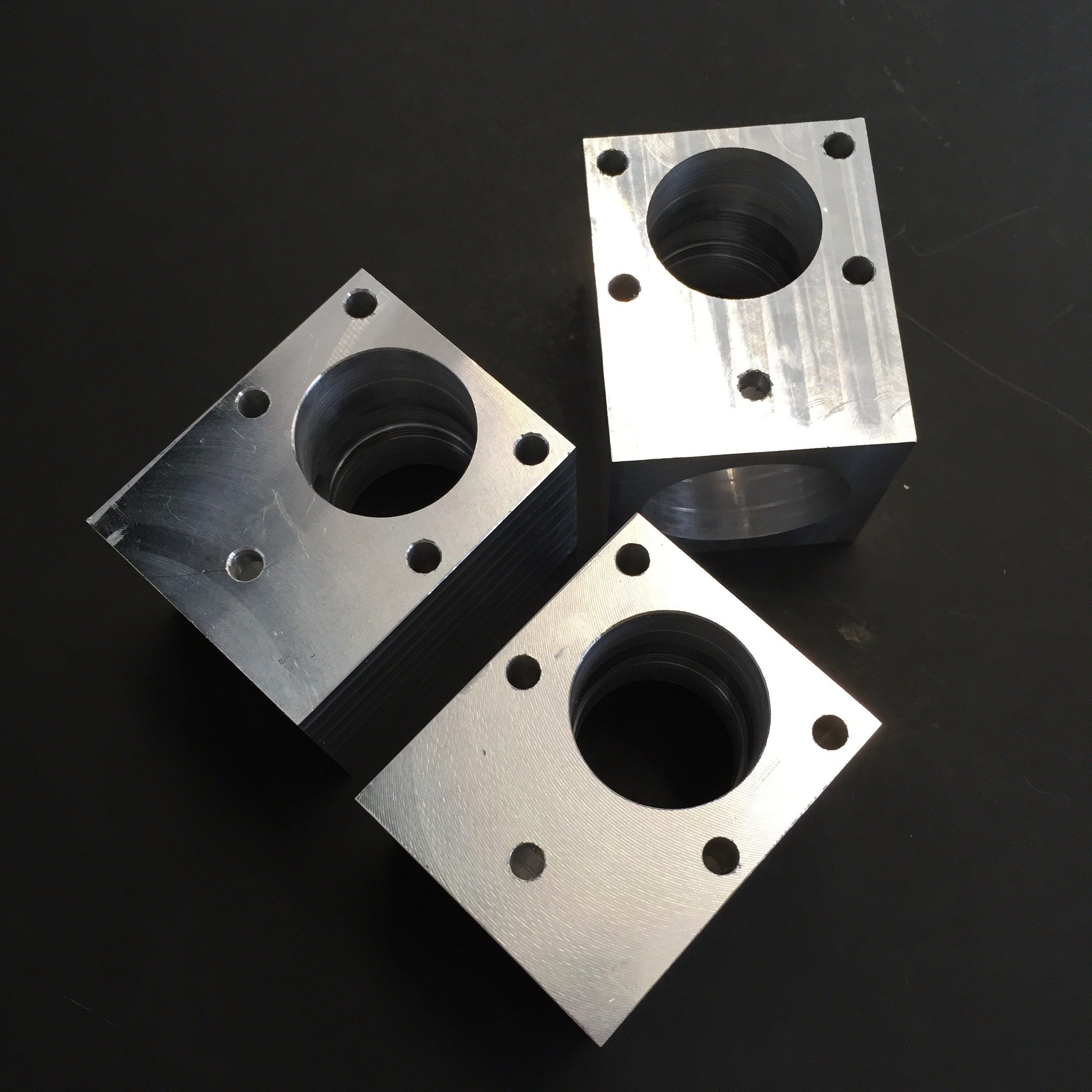
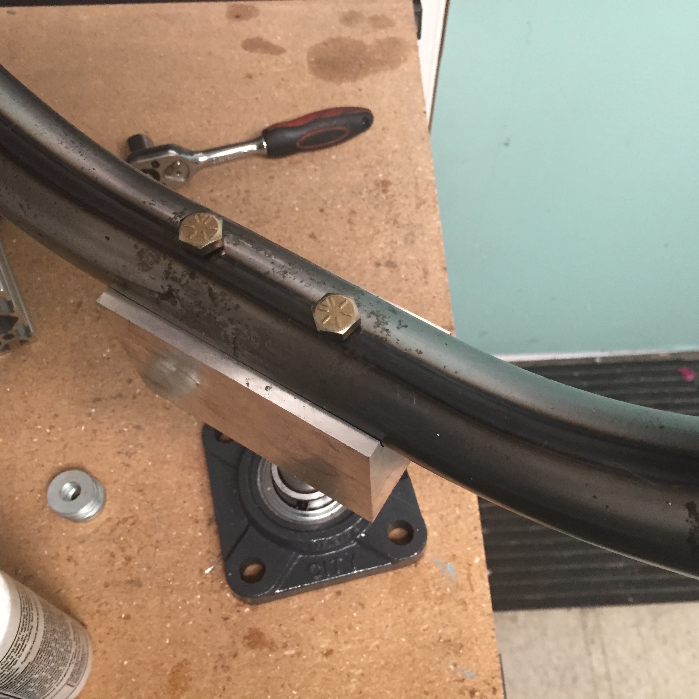
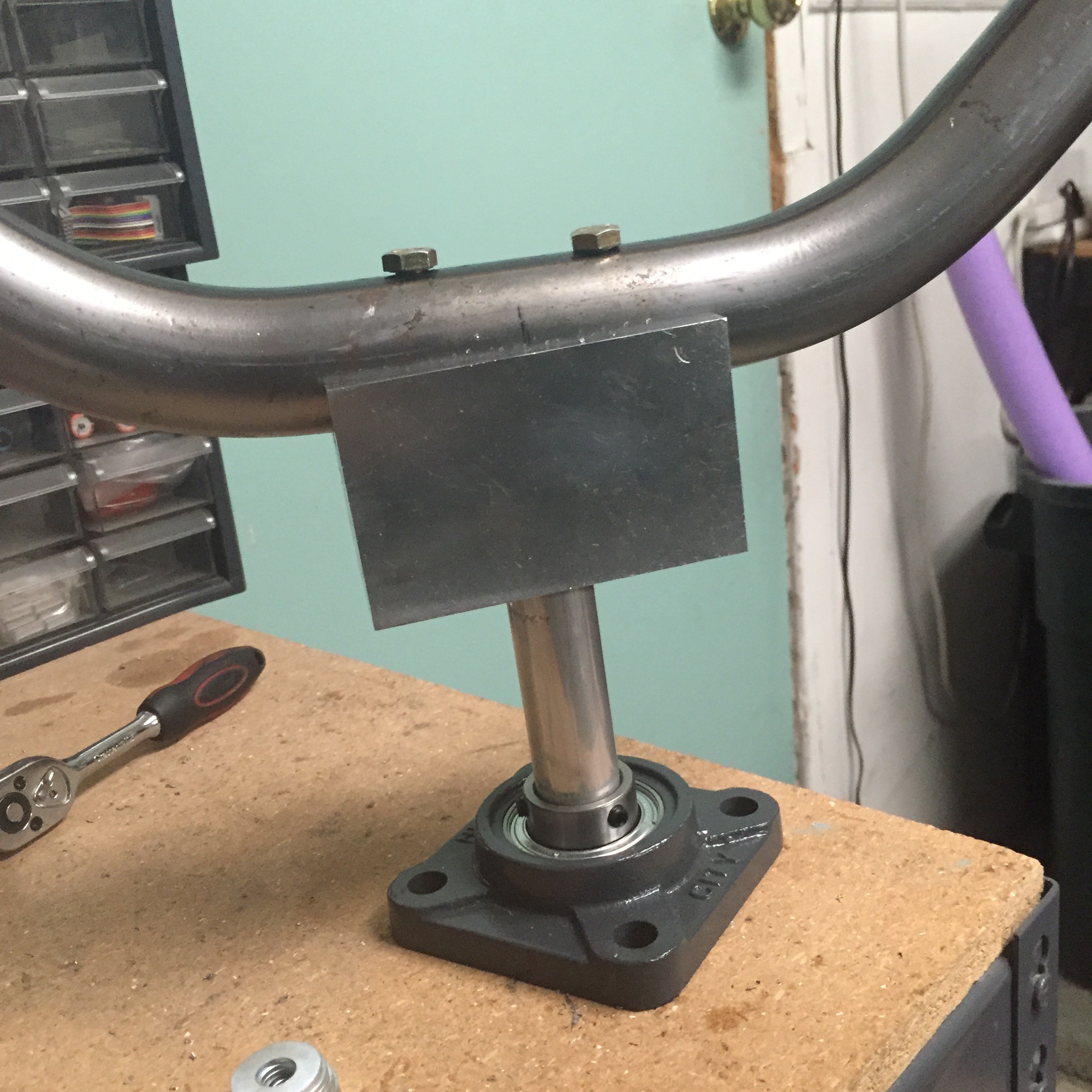
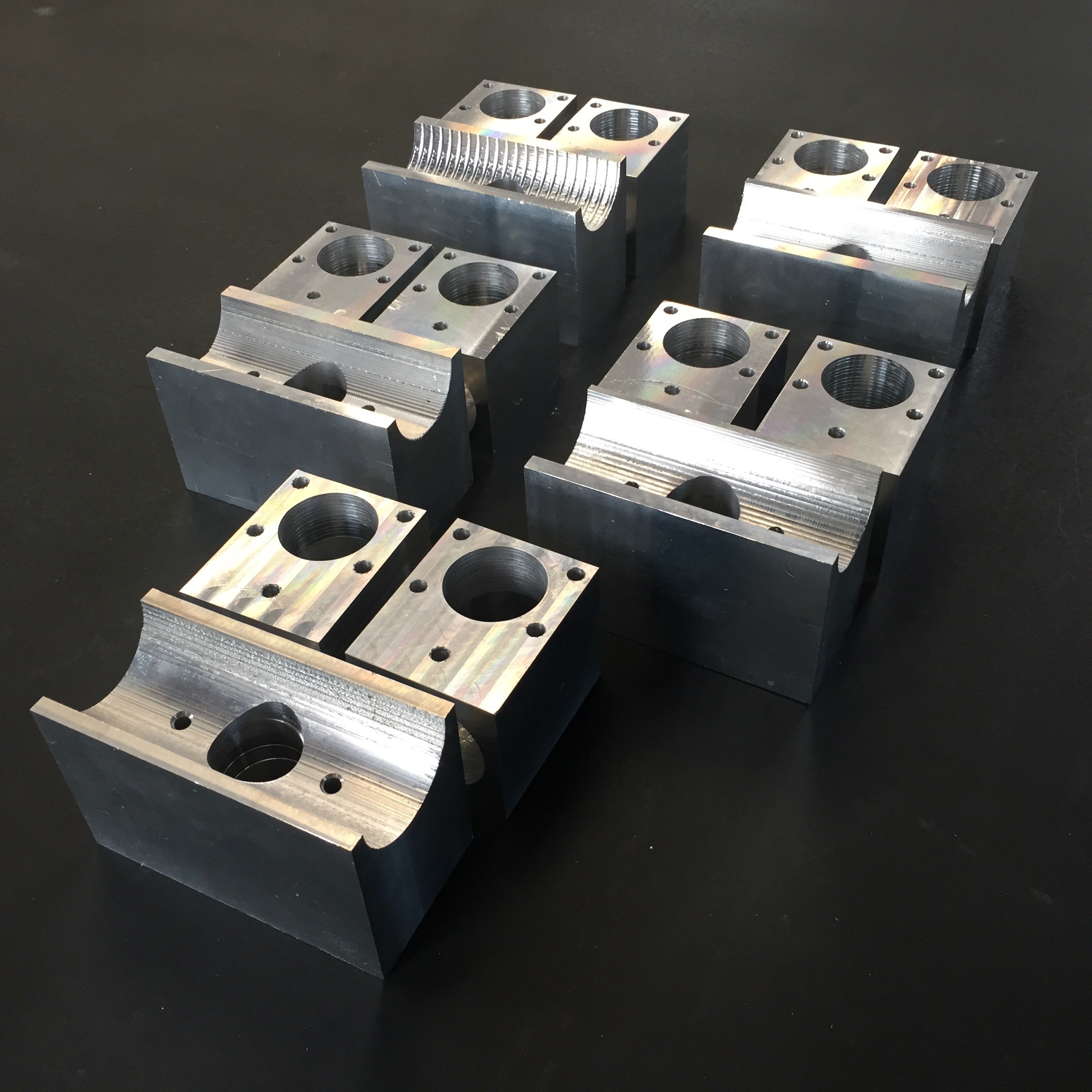
One thing I wanted to make double sure of was that the distances between the screen and my optics were correctly calibrated for focus, so I powered up the screen with one of the tabletop power supplies and did a few tests.![]() With a big push from Dan, we were able to bust out most of the pitch bearing blocks needed for these next few scopes too. That should put me in a good place to have any milling I'll need done by the end of the residency.
With a big push from Dan, we were able to bust out most of the pitch bearing blocks needed for these next few scopes too. That should put me in a good place to have any milling I'll need done by the end of the residency.![]()
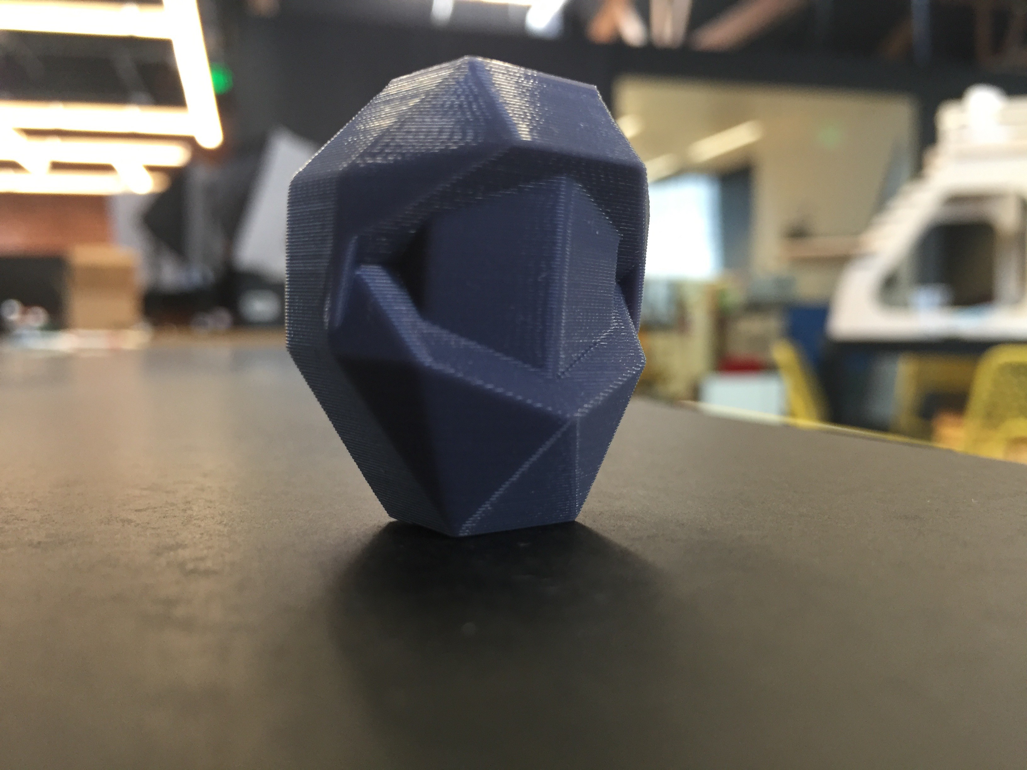
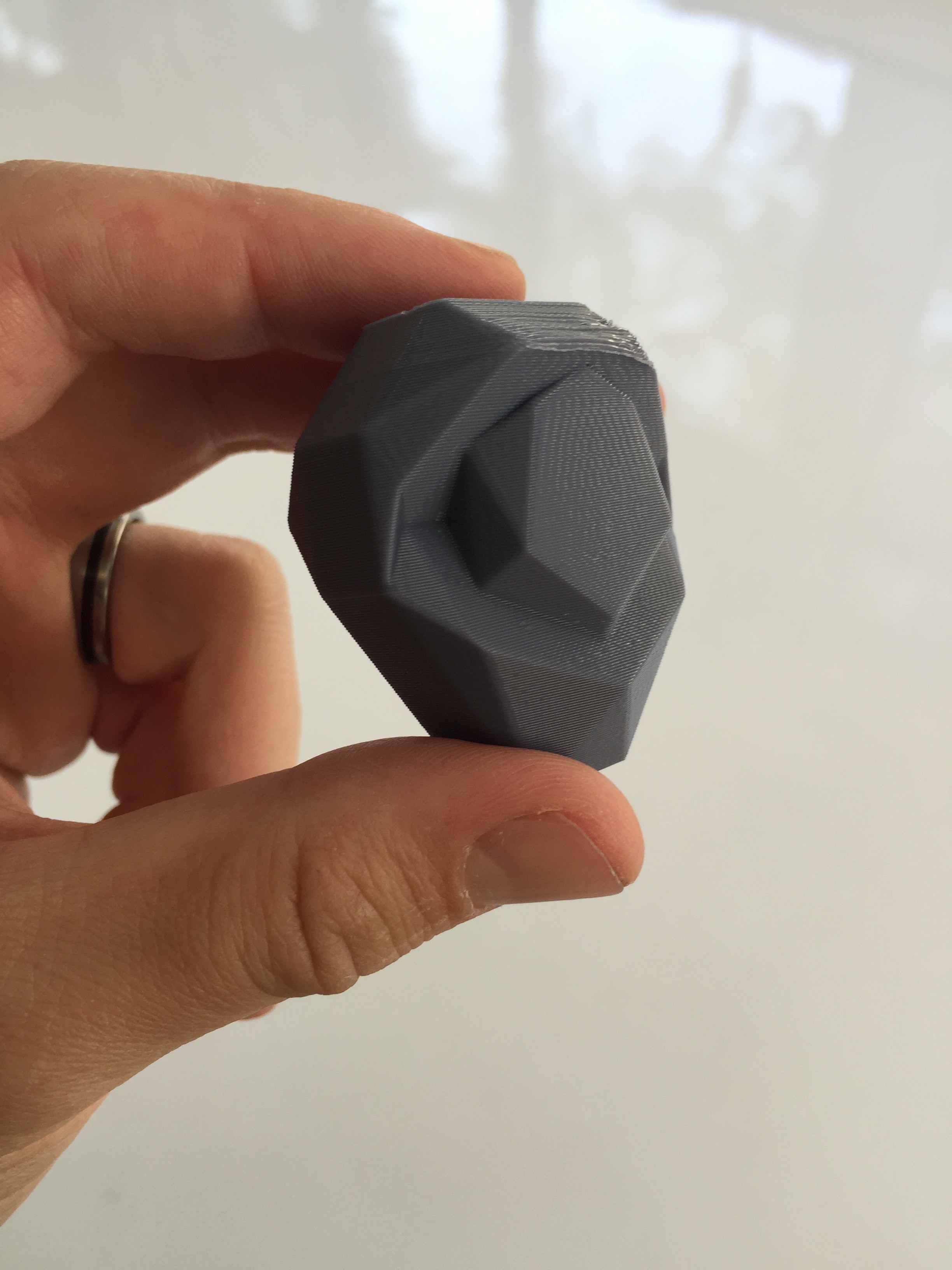
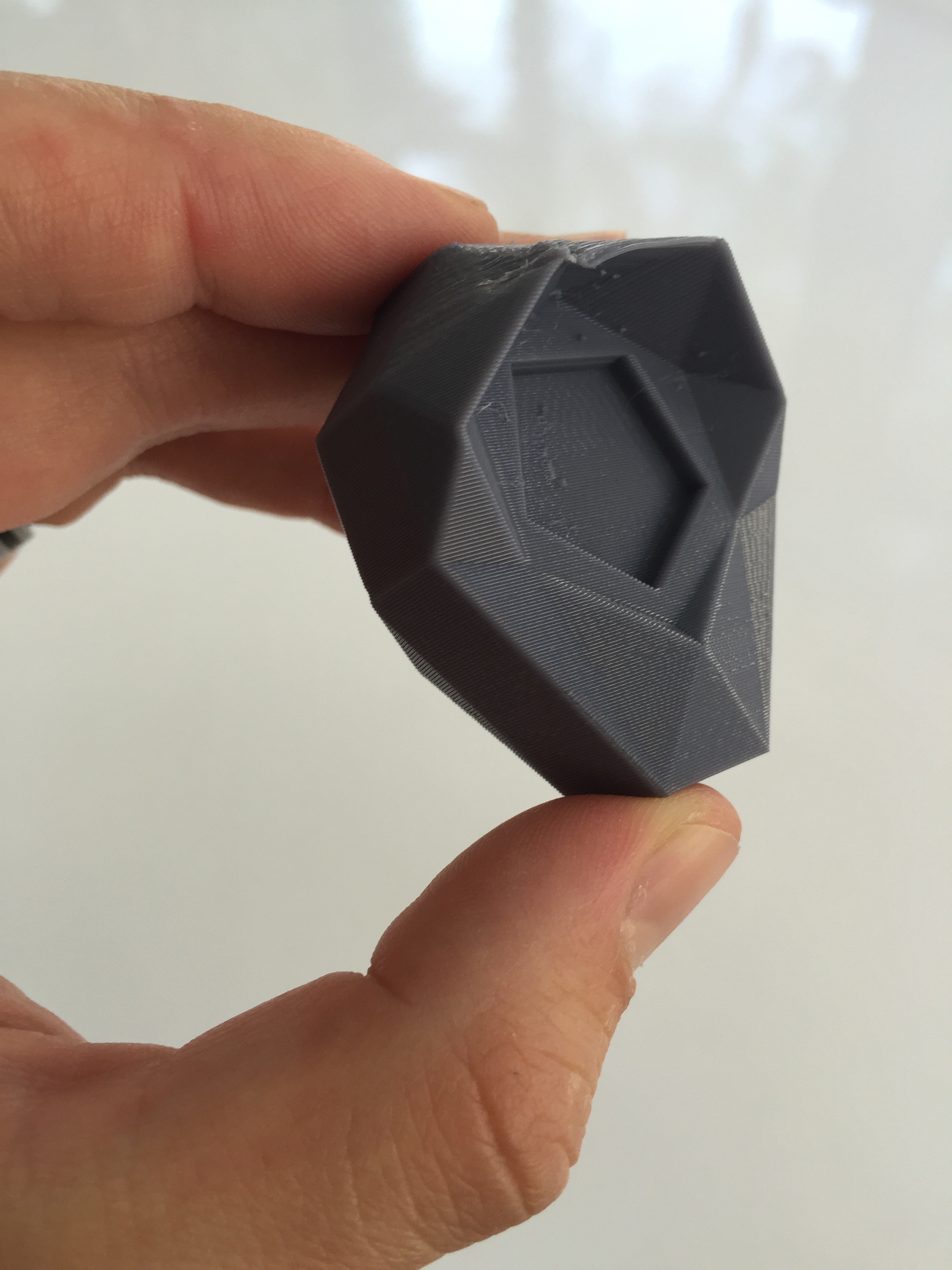
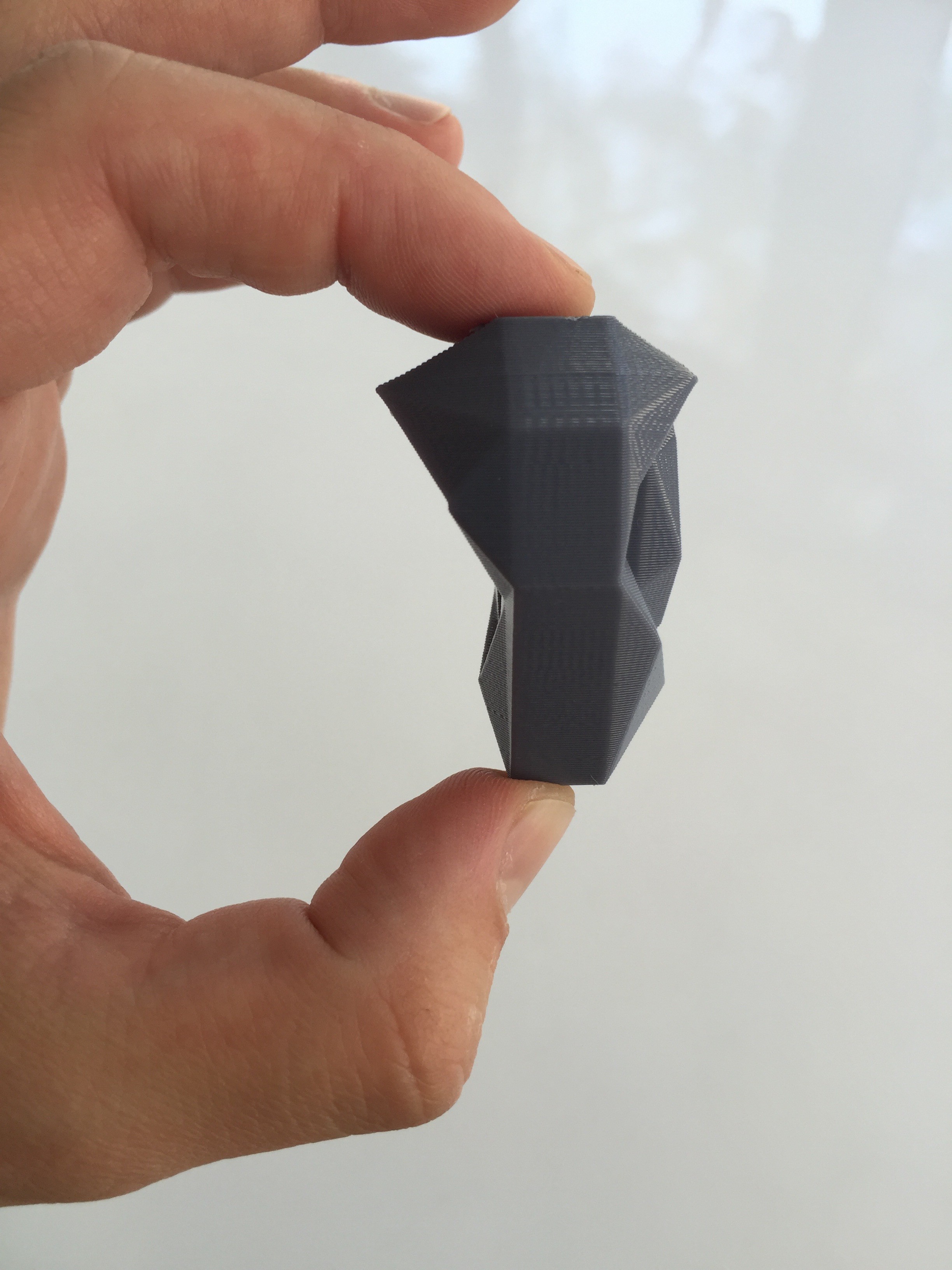
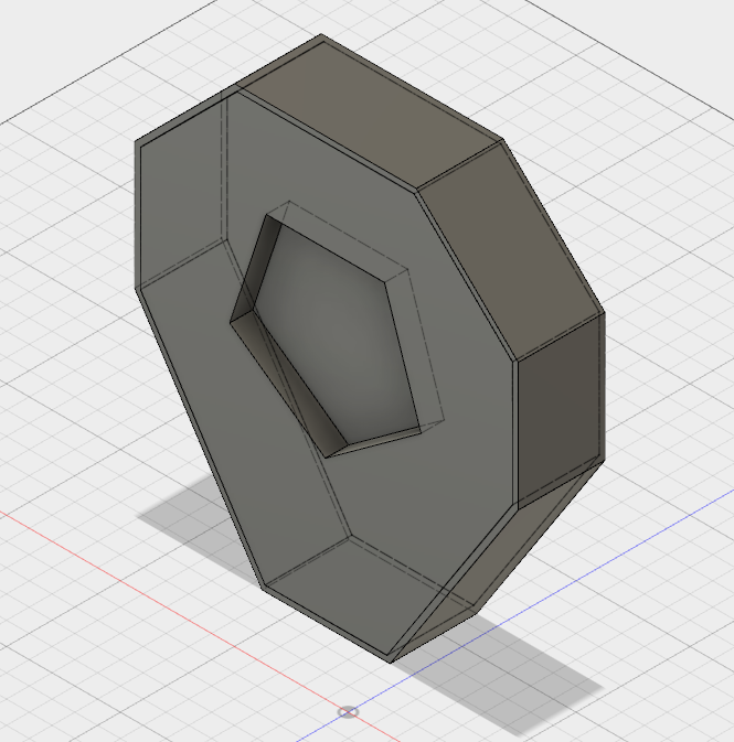
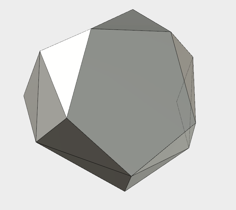
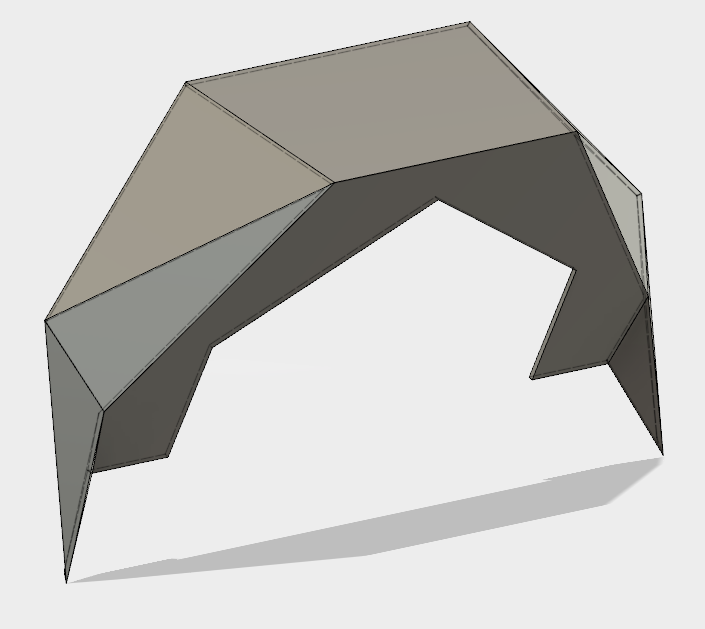
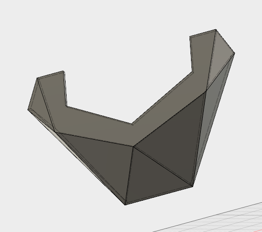
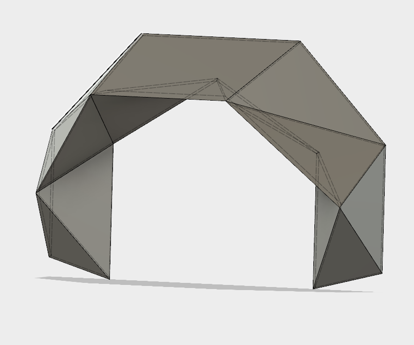
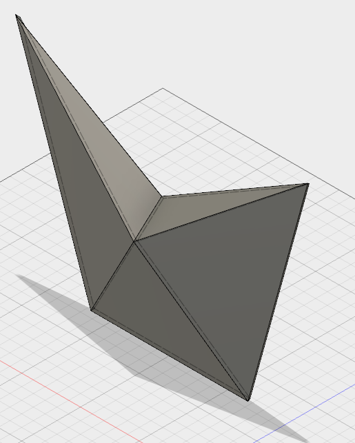
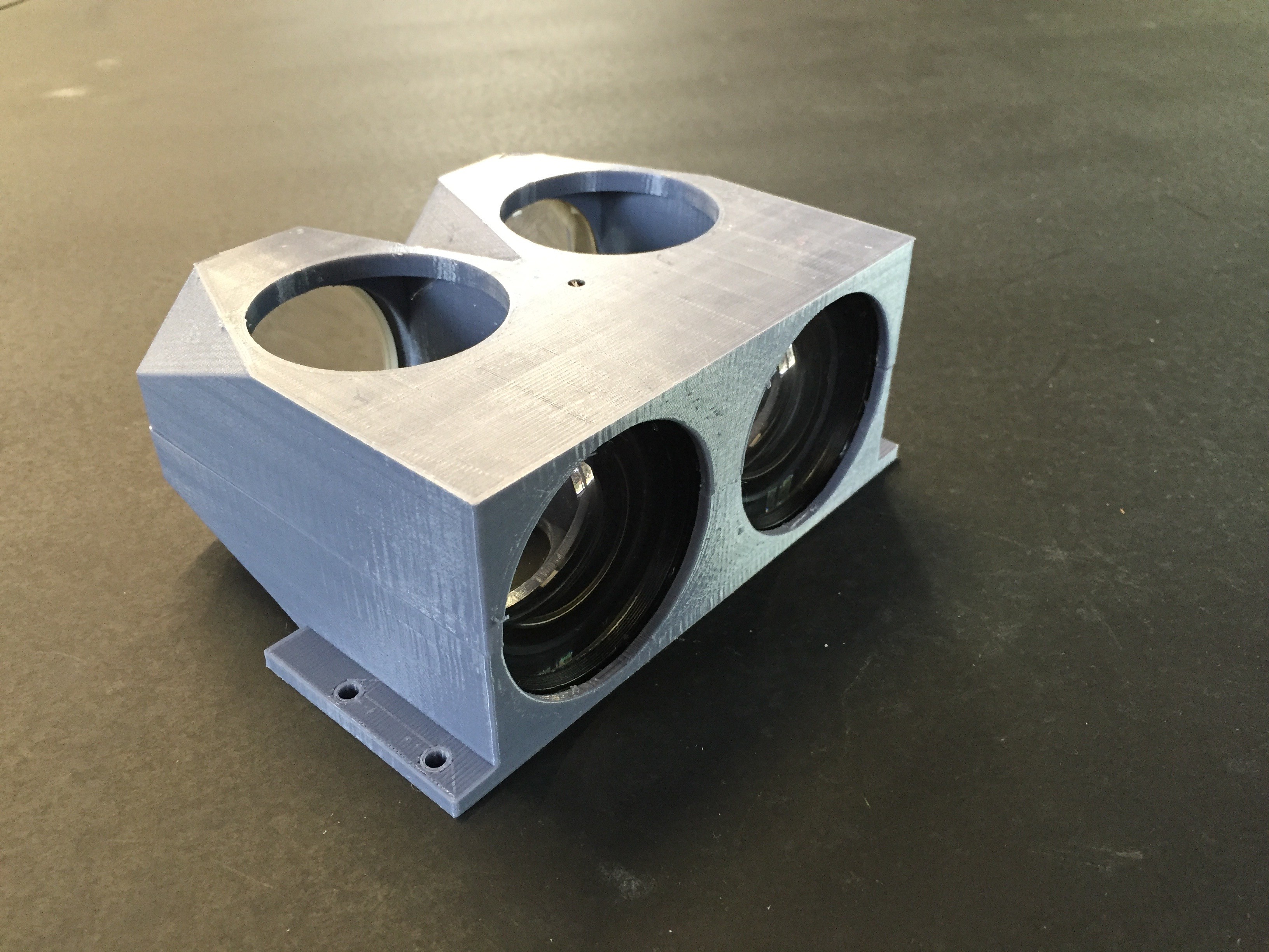
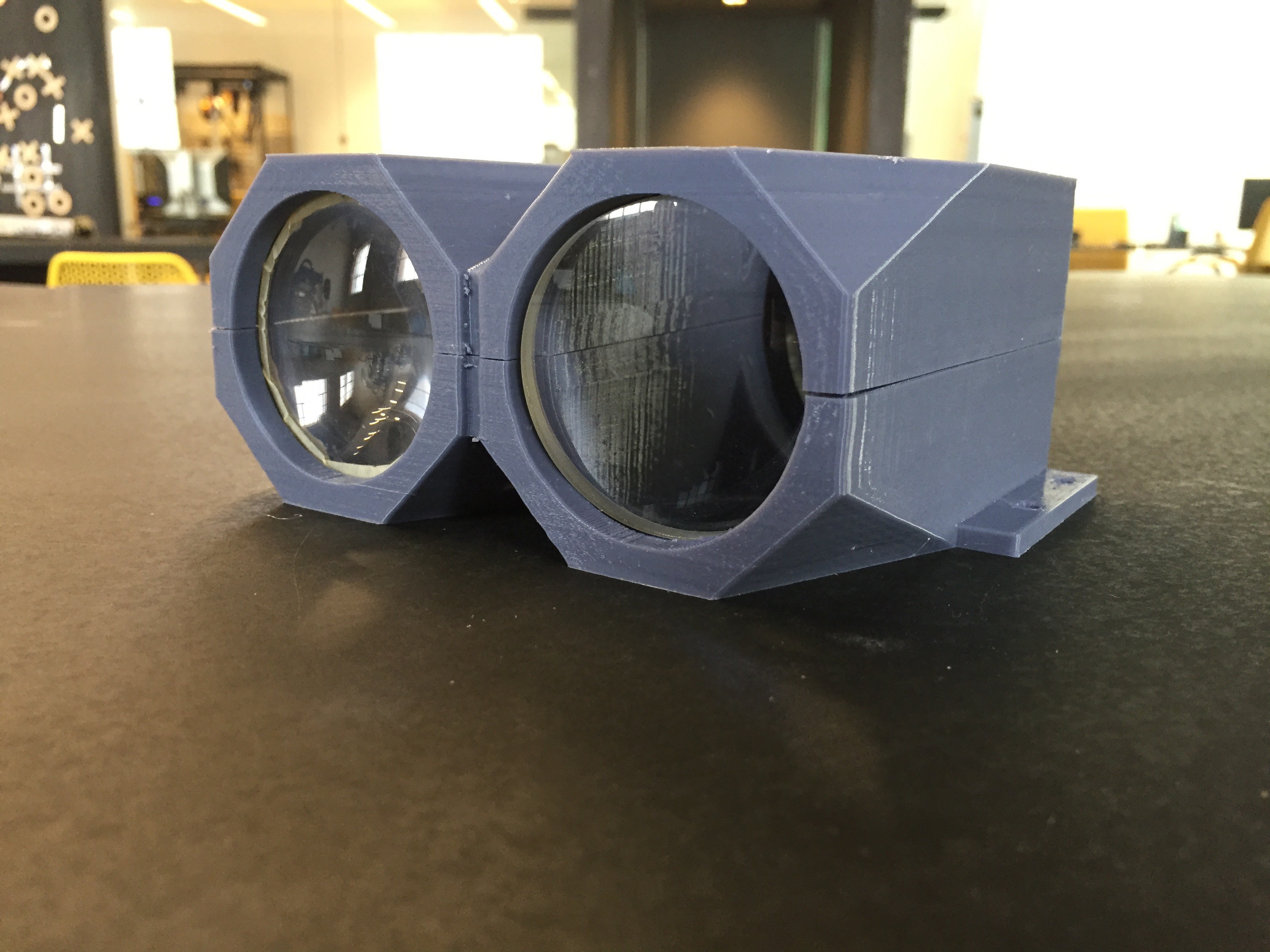
I've also been iterating on the shell design. Before I go into production of the positive, I wanted to make sure the whole thing made sense from a manufacturing and design perspective. I made another scale model to get a sense of what it feels like. There's still some tweaking once I get my final measurements figured out, but I'm liking where it's going.
![]()
Perceptoscope
A public viewing device for mixed reality experiences in the form factor of coin-operated binoculars.

 The Activate Fellowship was focused on the hyperlocal. Fellows are based in their city council district, and expected to build an action plan to implement with local leaders on the ground. We went through monthly leadership and advocacy training, got to explore a variety of influential community arts organizations, and were given introductions to important civic decision makers that could link us to opportunities or collaborators.
 The geometries are a bit tricky right there. I'd have to take into account both the angle of the shell relative to the corner of the frame, as well as the outward draft angle of the shell itself.
 Feeling inspired by the power of hot air, I took the rework station to the edges of the shell, and heated up the ABS so I could bend the excess plastic inward. Cleaned up and mounted, the main assembly of the newest Perceptoscope is complete.
 Now I just needed to glue all the pieces together to a backing board, and start filling in all the gaps that remain.

 One thing I wanted to make double sure of was that the distances between the screen and my optics were correctly calibrated for focus, so I powered up the screen with one of the tabletop power supplies and did a few tests.
 With a big push from Dan, we were able to bust out most of the pitch bearing blocks needed for these next few scopes too. That should put me in a good place to have any milling I'll need done by the end of the residency.