-
1Step 1
Cut off a few inches of the soft copper pipe. I have also used type L rigid copper pipe, but it really wasn't worth the trouble to use the harder copper. For this one, I use 3/8in ID soft copper, and it cut relatively easily with metal shears.
Cut down the length of the pipe. Flatten it out.
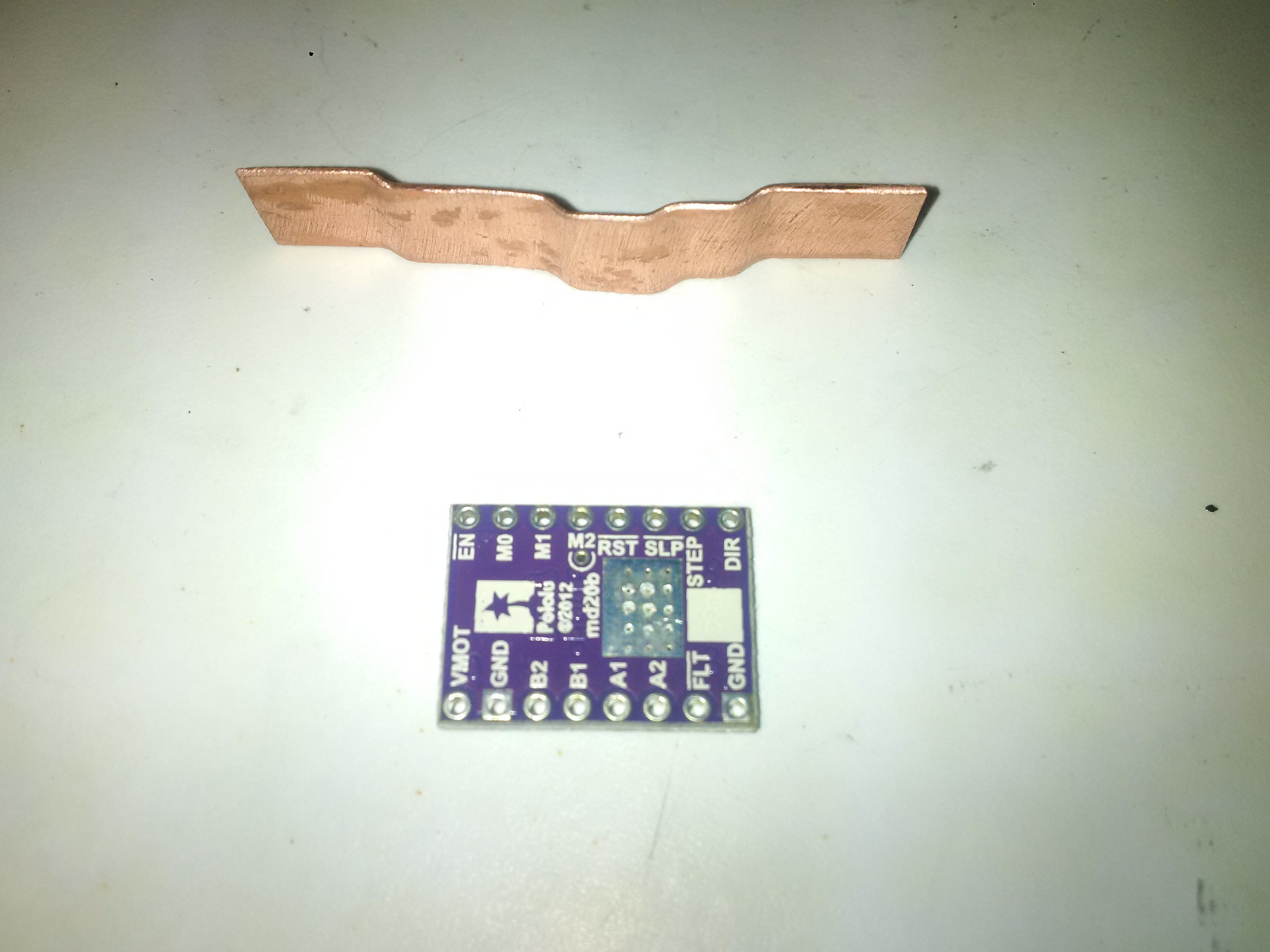
Cut it into a strip, as long as your stepper is tall plus a little more. Bend to this shape. Just a pliers and your fingers are good enough to bend it.
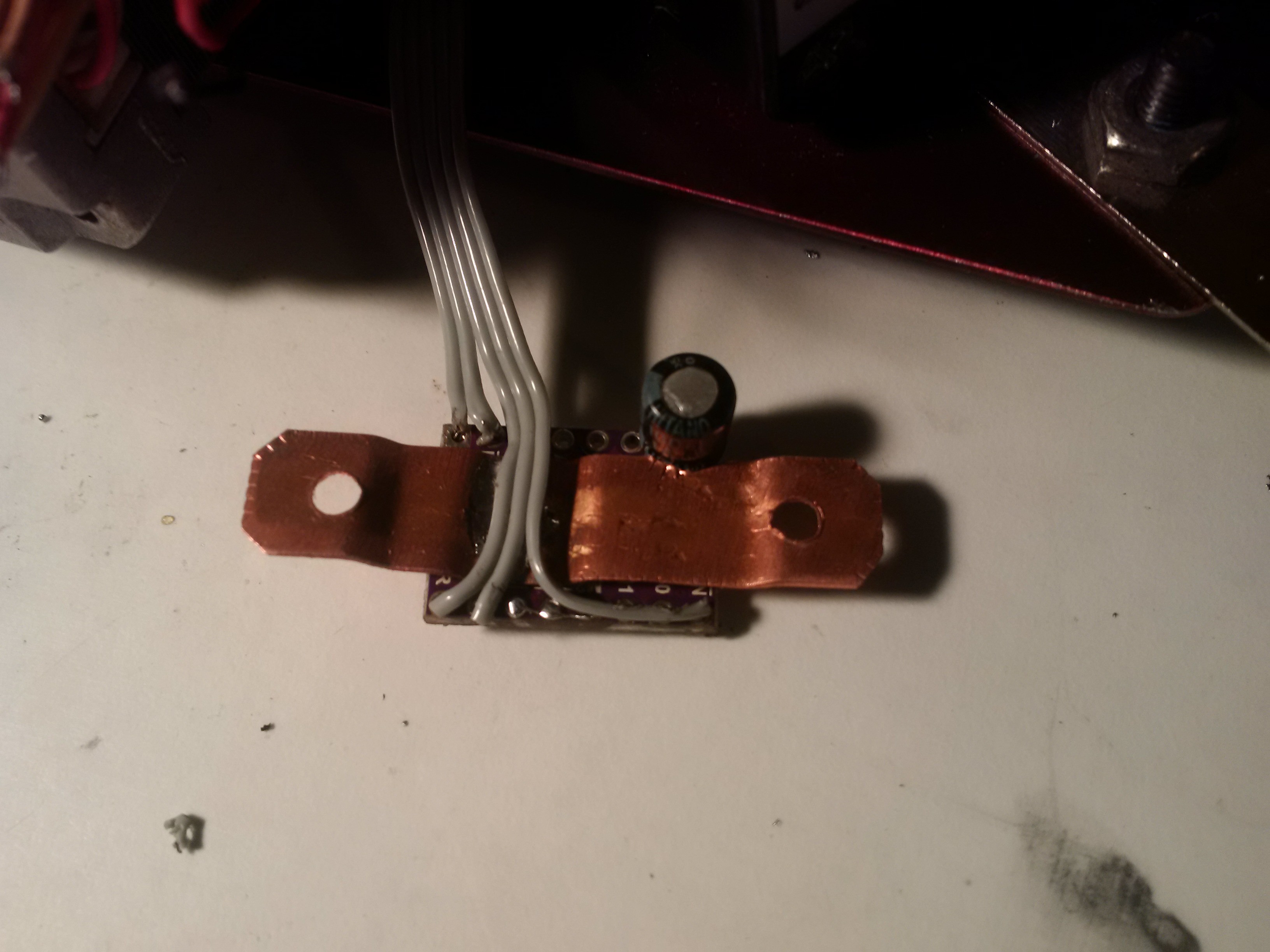
![]()
The middle bend keeps the copper off the board and lets you run wires under it.
Keep the crowned section about the size of the solder pad area on the back of the driver.
Avoid the current ref test point, circled above, when you are soldering later or you'll probably be buying another driver carrier.
-
2Step 2
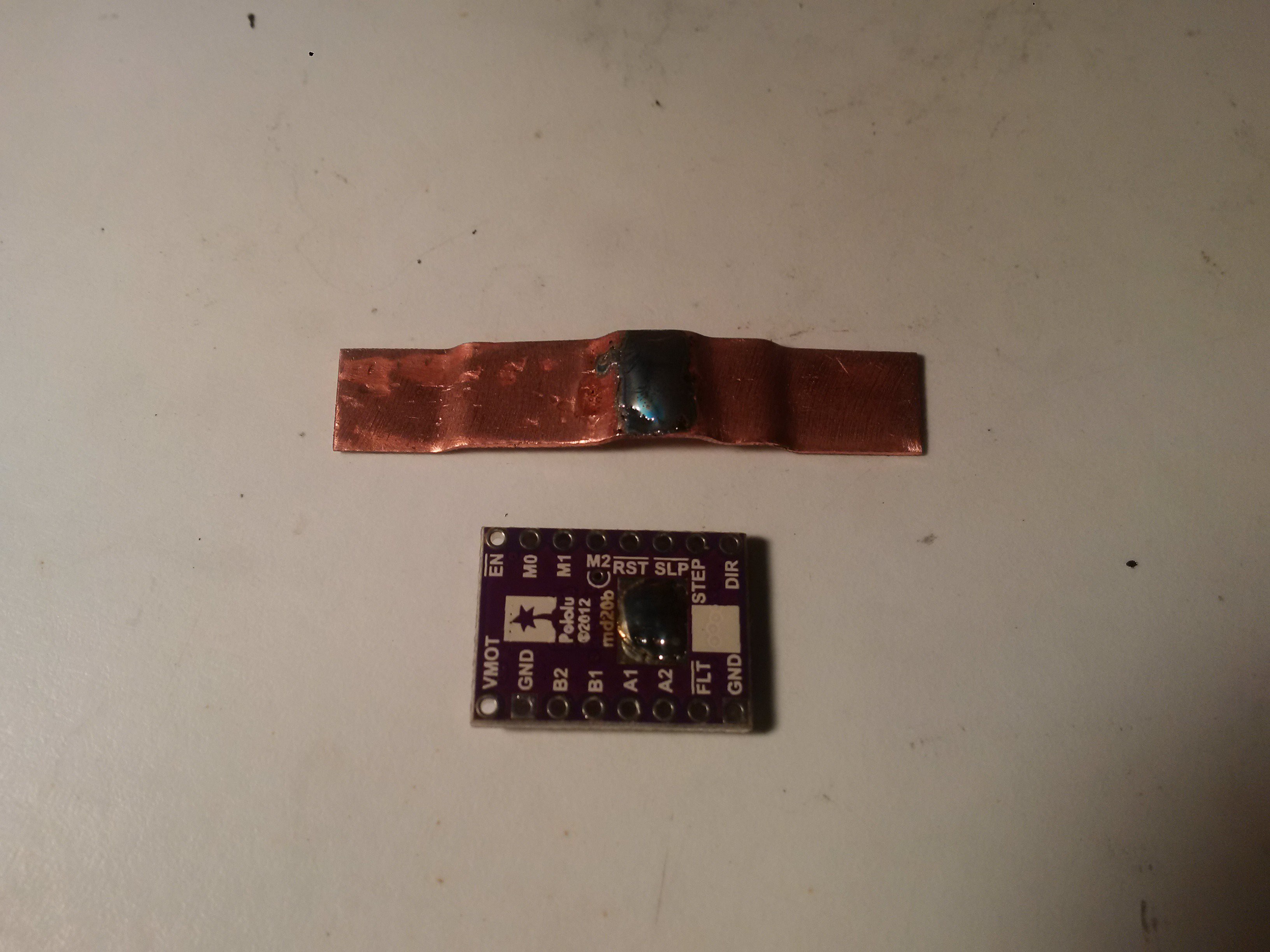
Tin the copper and driver.
![]()
After you got them well covered, remove as much solder as you can from your tinning... Heating them up and dropping them works well.
Don't overheat the driver too much or you could loose components on the other side..
Now would be a good time to put it on you stepper, mark where the holes need to be, and drill them. Be careful drilling this stuff... It cuts like butter, but if it grabs it will wind itself right around your drill bit and turn into a nice spinning blade. Wear gloves.
-
3Step 3
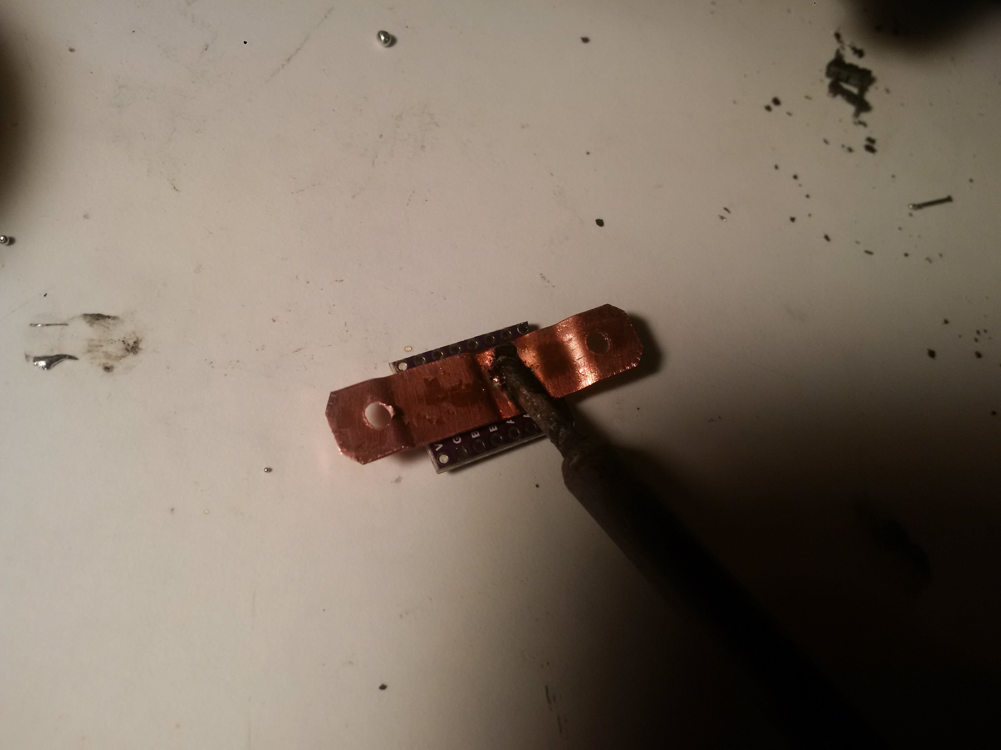
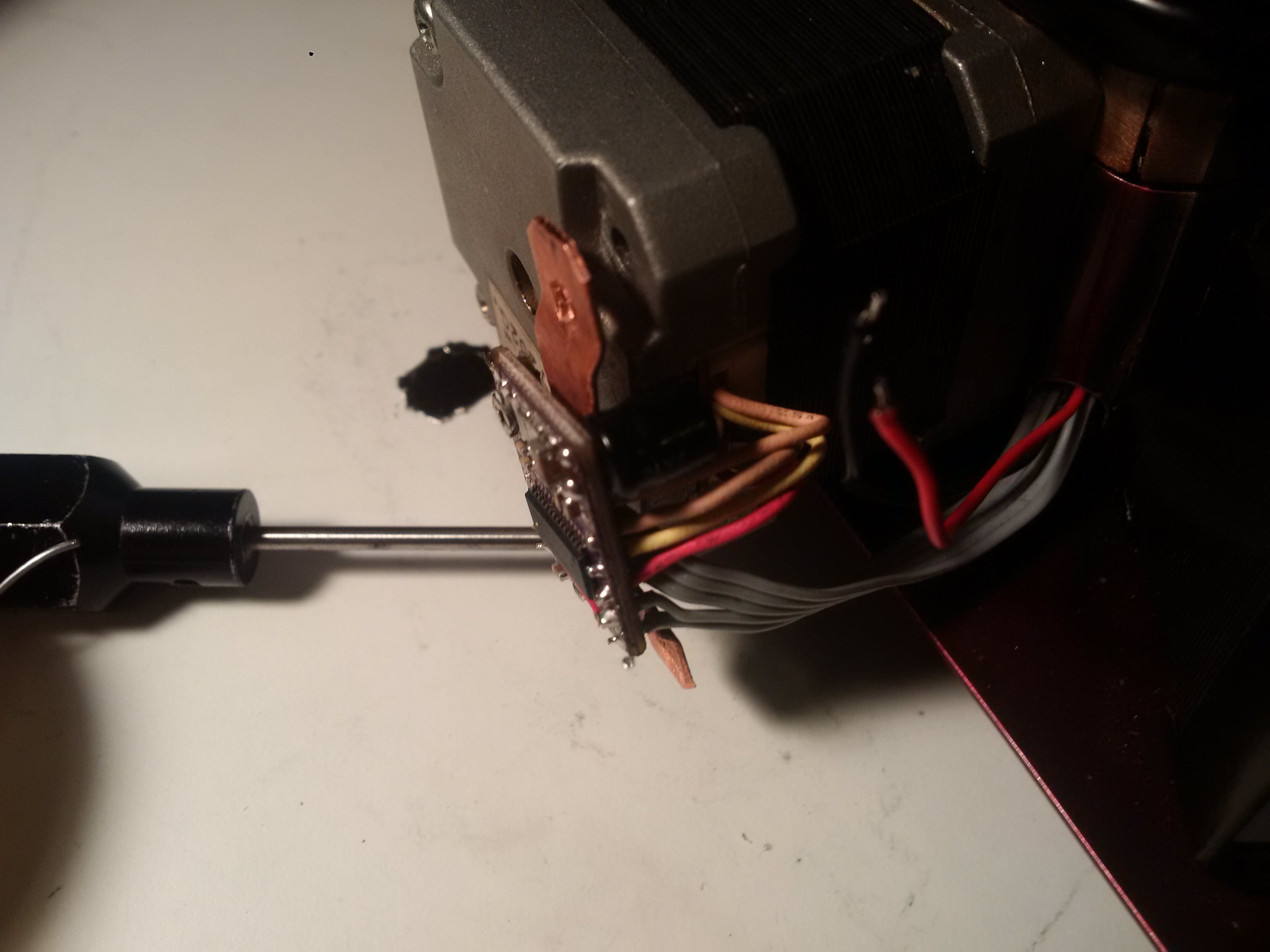
Stack them up carefully, heat with your soldering iron until they bond.
![]()
Put a screwdriver next to your iron to keep them together, and remove your iron.
-
4Step 4
Wire it up.
![]()
For a DRV8825, the above is a little more than the minimum required wiring, and not where they document things go..
Starting from the bottom left going counter clockwise...
Pin 1 becomes digital ground (explained later).
Pin 2,12,13,14 get wired together, and fed with 3.3-5v digital power, resulting in hard-wired 1/16th micro-stepping.
Pin 3,4,5,6 are where you terminate your stepper windings.
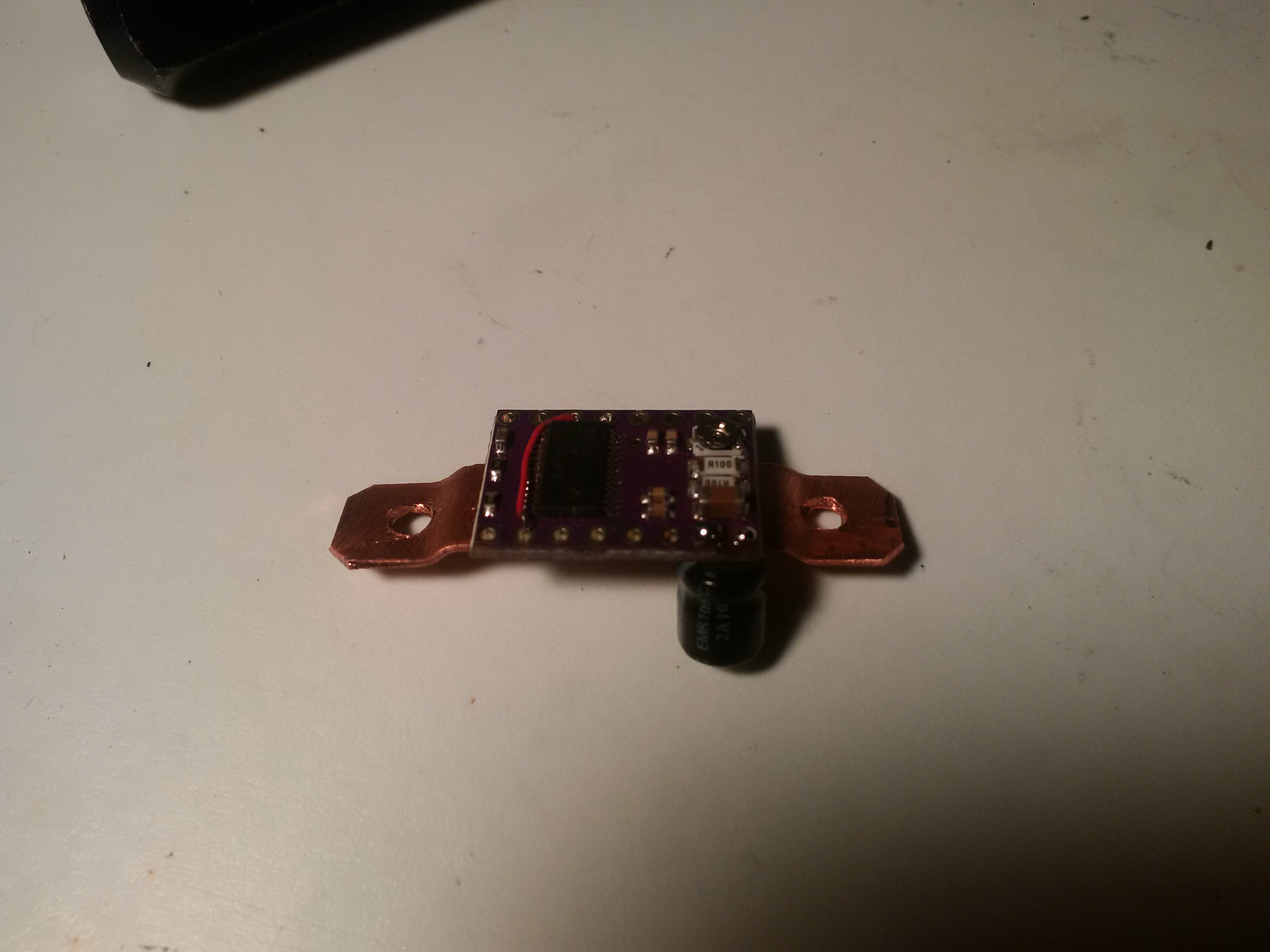
Both pin 1 and 7 are documented as ground, and from some measuring (and attempts at soldering) both attach directly to the multi-layer ground plane of the driver, and to the substrate of the chip. So, for a cleaner install, I fed motor ground/motor power to pins 7/8 respectively. I also mounted my bypass capacitor directly to the board, on the back. In my experience, they tend to get broken off on the top, which will destroy your driver.
Pin 8 is Not Enable. I used it. You don't have to.
Pin 15/16 are Direction/Step respectively.
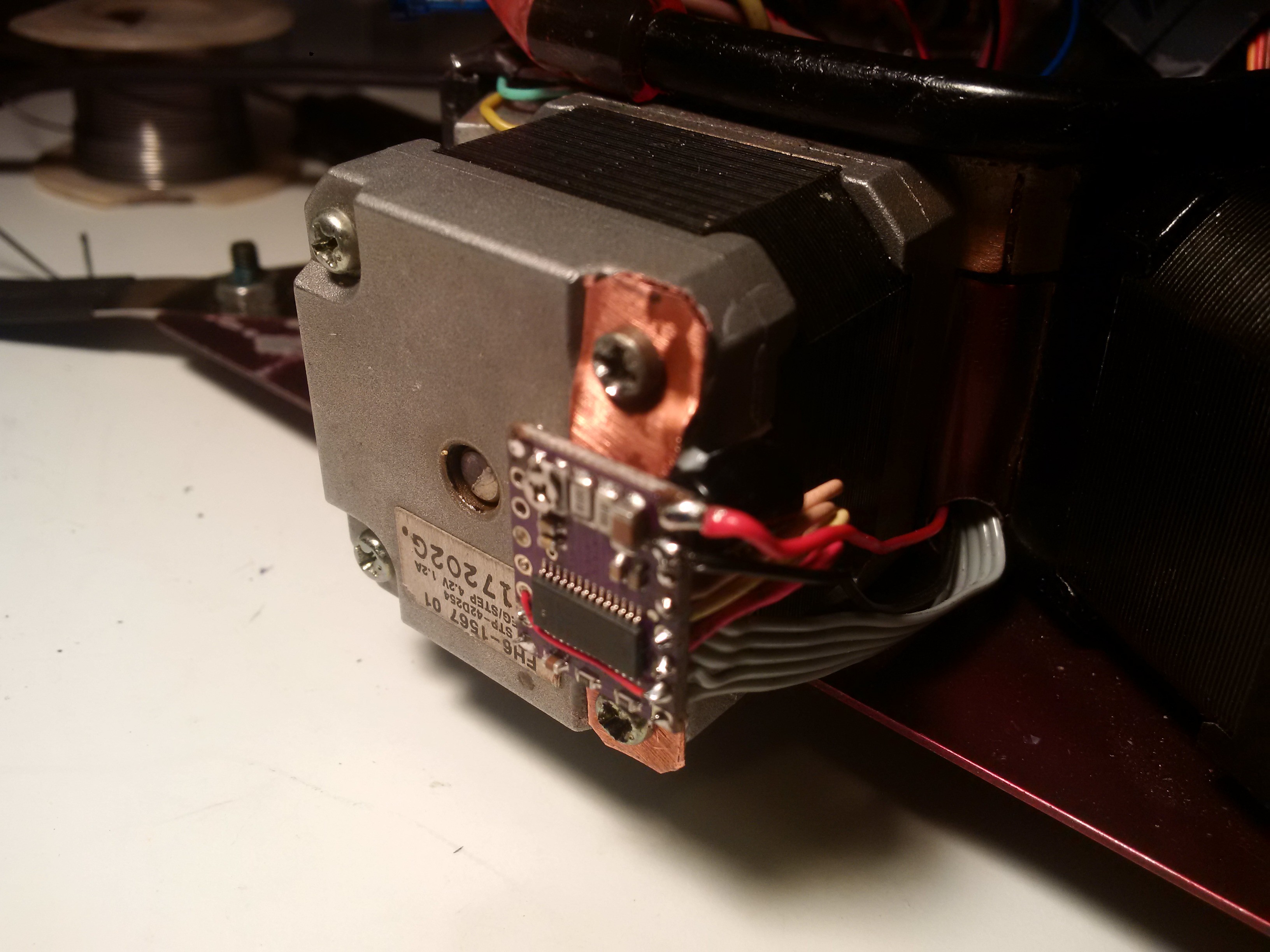
Here is how I did it, for a pretty clean result.
![]()
-
5Step 5
Wire it to the stepper.
![]()
-
6Step 6
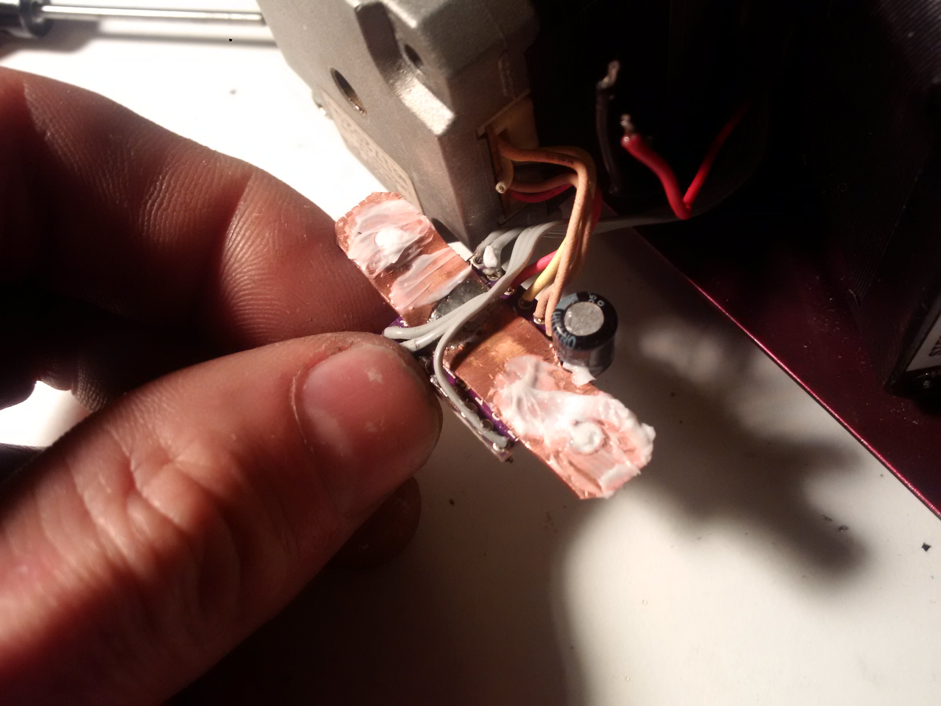
Some heat sink compound..
![]()
Now your driver is thermally bonded to your stepper, which makes a pretty good heat-sink.
Sadly, this doesn't also protect your steppers from overheating. The thermal shutdown temperature for these drivers is well above the point at which you would start to demagnetize your stepper.
-
7Step 7
Replace the existing screws. Connect power.
![]()
-
8Step 8
Properly set the current.
You may have noticed we covered up the current ref test point. No worries.
The same reading can be taken from the adjustment pot itself.
For the DRV8825, the current setting formula is dead simple.
(output current) = (voltage measured at the test point) x 2
So for my 1.2A stepper here, I set the voltage as measured with respect ground (the copper is also ground) and the pot, to 0.6V.
Then I backed it way down... right to where stepper skips, just before stripping the filament. Perfect.
 MasterOfNull
Discussions
Become a Hackaday.io Member
Create an account to leave a comment. Already have an account? Log In.