Working on the code for walking, I managed to somehow damage the ESP-12 module I was using -- it would get in a boot loop, and refuse getting into the right boot mode even with the GPIO2 held down. After checking everything, I removed the board from the robot, checked everything once more, made a couple of measurements with the multimeter to make sure there are no shorts or breaks, and, running out of ideas, left it there for some time. Then I tried once more time, and it worked this time -- I could flash it again. However, I decided that I'm not going to rely on this module anymore (it's not an original one), and since the PCB I used had a number of mistakes that I had to work around, I decided to make a new board (I will still work on the program using the old one, while the new one is getting fabricated).
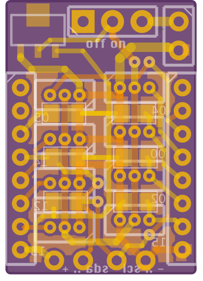
So here it is:

This time the PCB is exactly the same size as the ESP12 module. I managed to squeeze all the servo sockets and the resistors in there, and then decided to also add a voltage regulator (who knows, maybe the old module died because of wrong voltage) and some room for the power switch. Since there wasn't really any room for those, I put them under the wifi antenna of the module. Yes, I know that it will lower the range of the module and possibly introduce some interference. In the worst case I will redesign it again. The challenge was squeezing an additional power line in there (the servos still use the un-regulated power straight from the battery), but I managed to do it with just a couple of vias. The boards are ordered, should arrive in a couple of weeks.
Once I had that done, I started to think about where it would be best to put that board on the pony itself. So far it has been strapped to the tail, because that was the largest free area, but it didn't look right. Finally, I decided to put the brain in the head, roughly in the same place where the real brain would be in a real pony. So I went to the design files, and made a hole in the head to hold that PCB. I also made some additional holes for the servo holders, and added the holders to the design file (with a hole in the middle for the wires):

And I sent that to fabrication too. This time in a nice violet color, and in 2mm thick acrylic.
 deʃhipu
Discussions
Become a Hackaday.io Member
Create an account to leave a comment. Already have an account? Log In.