Tobias
-
Five Months Later
02/09/2017 at 02:23 • 0 comments![]()
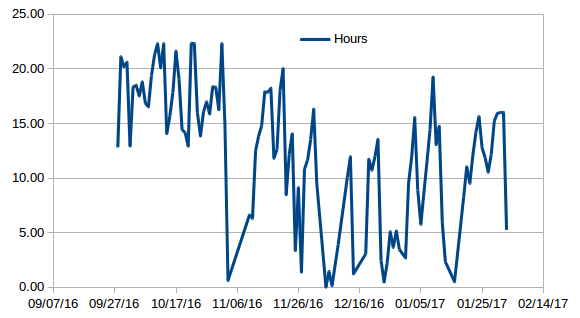
The system has been working autonomously since September 2016. The watchdog features to prevent the system from hanging apparently are working. The solar panels look dirty/sticky but still work fine. Here is a graph showing the number of hours the system was operating each day:
![]()
-
Long term testing
09/27/2016 at 01:29 • 3 comments![]()
A waterproof outdoor enclosure was added for long term testing.
![]()
After three days of working, the system got into a state where the relay to the Raspberry Pi was on, but the Pi was not running. Apparently, it is possible to turn on power to the Pi, but the Pi does not boot up. I have observed this behavior in the past. Obviously, this is not acceptable for an autonomous system. I changed the code on the Arduino so that it will power cycle the Pi if it detects that the Pi is not running. What is a good criterion to determine if the Pi is running or not? I chose the power consumption. The Pi draws at least 1000mW when it is running, so if the system power is below 900mW even though the battery voltage is high enough for the Pi to run, the Pi needs to be power-cycled. However, during boot, the power can be below 900mW, so an extra precaution for the power cycling is needed. I decided to take three successive power measurements, and if each of them is below 900mW, only then will the Pi be power-cycled.
-
Web-connected MPPT Solar Charge Controller
09/03/2016 at 22:31 • 0 comments![]()
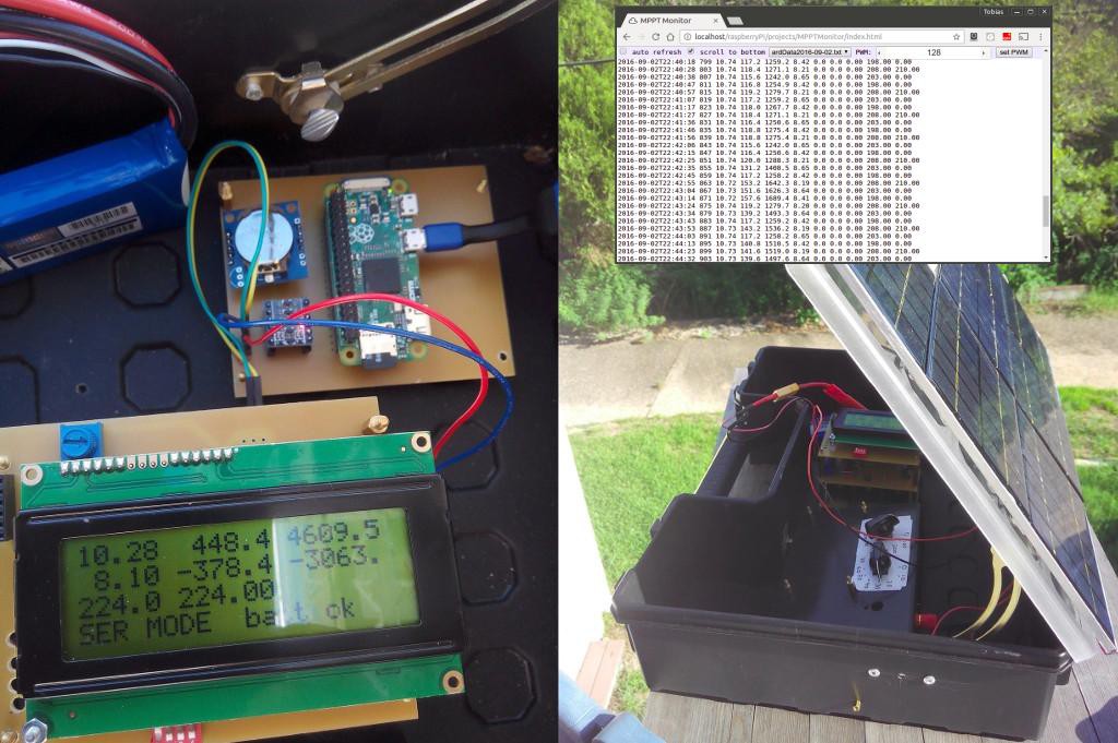
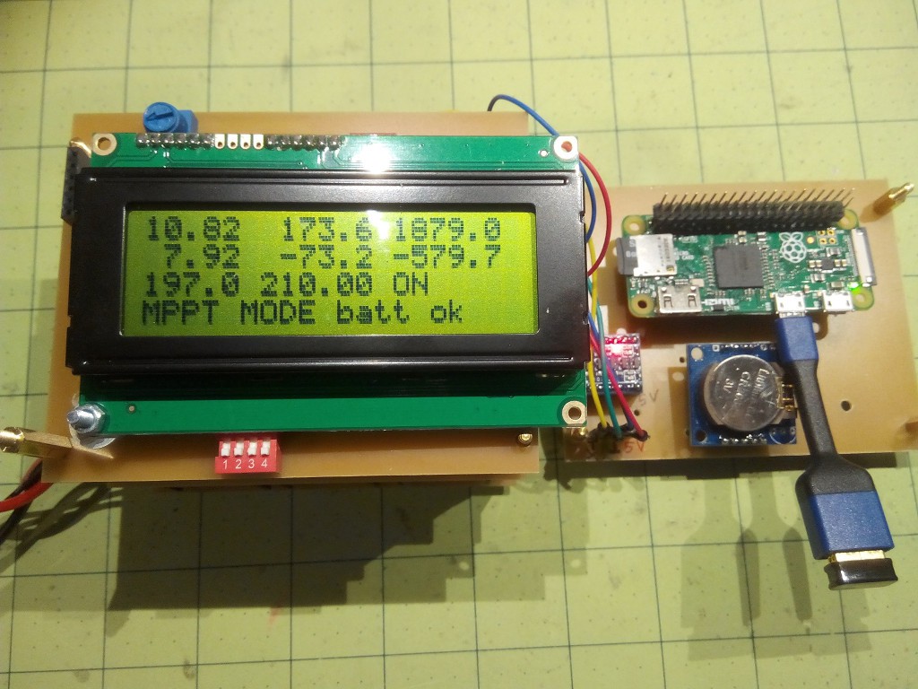
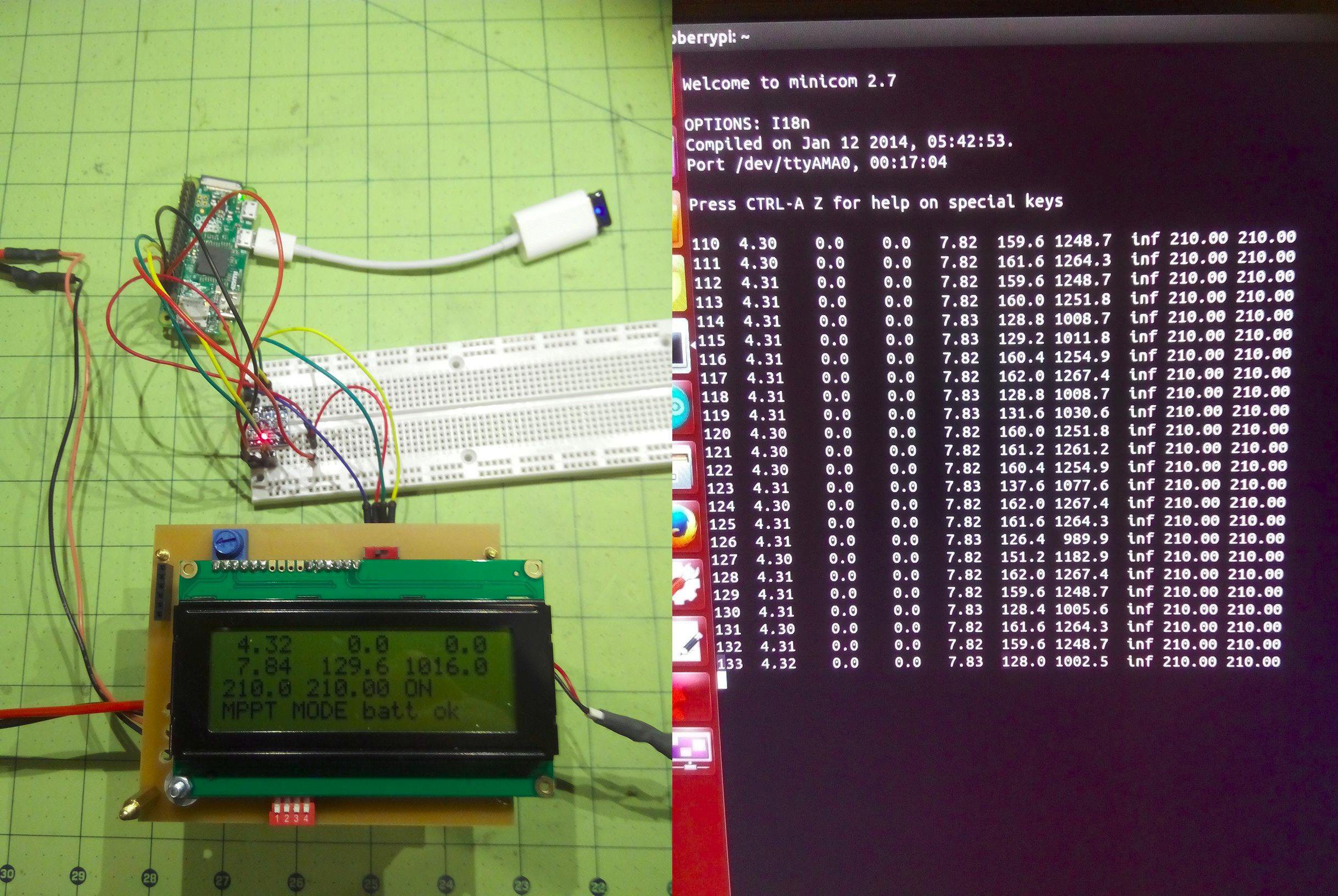
The most convenient way to communicate with a device on a network is through a web browser. The Raspberry Pi runs a Lighttpd web server which serves the web pages. This leads to the question of device access to the charge controller which is easily solved with the help of python-serial. Two of the DIP switches on the LCD board are used to configure the way the PWM percentage is controlled:
- MPPT
- Potentiometer
- serial port
In serial mode, a command is sent to the charge controller through the serial port which sets the PWM percentage and thus the voltage and the load on the solar panels. The web page has an interface to set the PWM. The ability to vary the PWM manually with a remote interface makes it easier to test the MPPT algorithm. The MPPT algorithm should automatically find the correct PWM for the maximum power point, and by switching to manual mode under the same conditions and finding the maximum power point manually, we can verify the MPPT operation.
![]()
-
Charge Controller Behavior
07/26/2016 at 05:54 • 0 commentsNow that I have a data logger, I can monitor the charge controller behavior. The first test is to make sure that the battery does not get charged beyond the 8.4 Volts, meaning that the PWM should lower the pulse width once the battery is full. In the chart, 100% pulse width is equivalent to the number 255 (one byte.) My algorithm in the Arduino first determines a target pulse width and then changes the actual pulse width by a small amount in each loop cycle. This smoothes out the PWM changes.
![]()
![]()
-
Arduino with charge controller plus Pi plus Wifi close to 1 Watt
07/15/2016 at 23:56 • 0 commentsPowering the Raspberry Pi Zero through the GPIO pins and leaving out the USB hub brings the power for the whole system down to between 1 Watt and 1.2 Watts:
![]()
Theoretically, a full 40 Watt-hour battery should be able to power the system for over 33 hours, so the system should easily be able to make it through the night until the sun comes up again.
Thanks to
https://oscarliang.com/raspberry-pi-and-arduino-connected-serial-gpio/
http://conoroneill.net/connecting-an-arduino-to-raspberry-pi-for-the-best-of-both-worlds/
http://codeandlife.com/2012/07/29/arduino-and-raspberry-pi-serial-communication/
Note: most links below are from 2013 and they are good for the hardware connections, but are outdated as far as software goes. There is no more /etc/inittab.
Instead, run
sudo raspi-configAnd disable serial boot messages and getty under Advanced -> Serial.
Now , serial is completely disabled (no AMA0 when ls /dev/tty*)
It needs to be re-enabled by
sudo nano /boot/config/txtand setting
setting enable_uart=1
Reboot and check ls /dev/tty* that /dev/ttyAMA0 is present.
Then,
minicom -b 9600 -o -D /dev/ttyAMA0 -
Direct serial communication vs USB
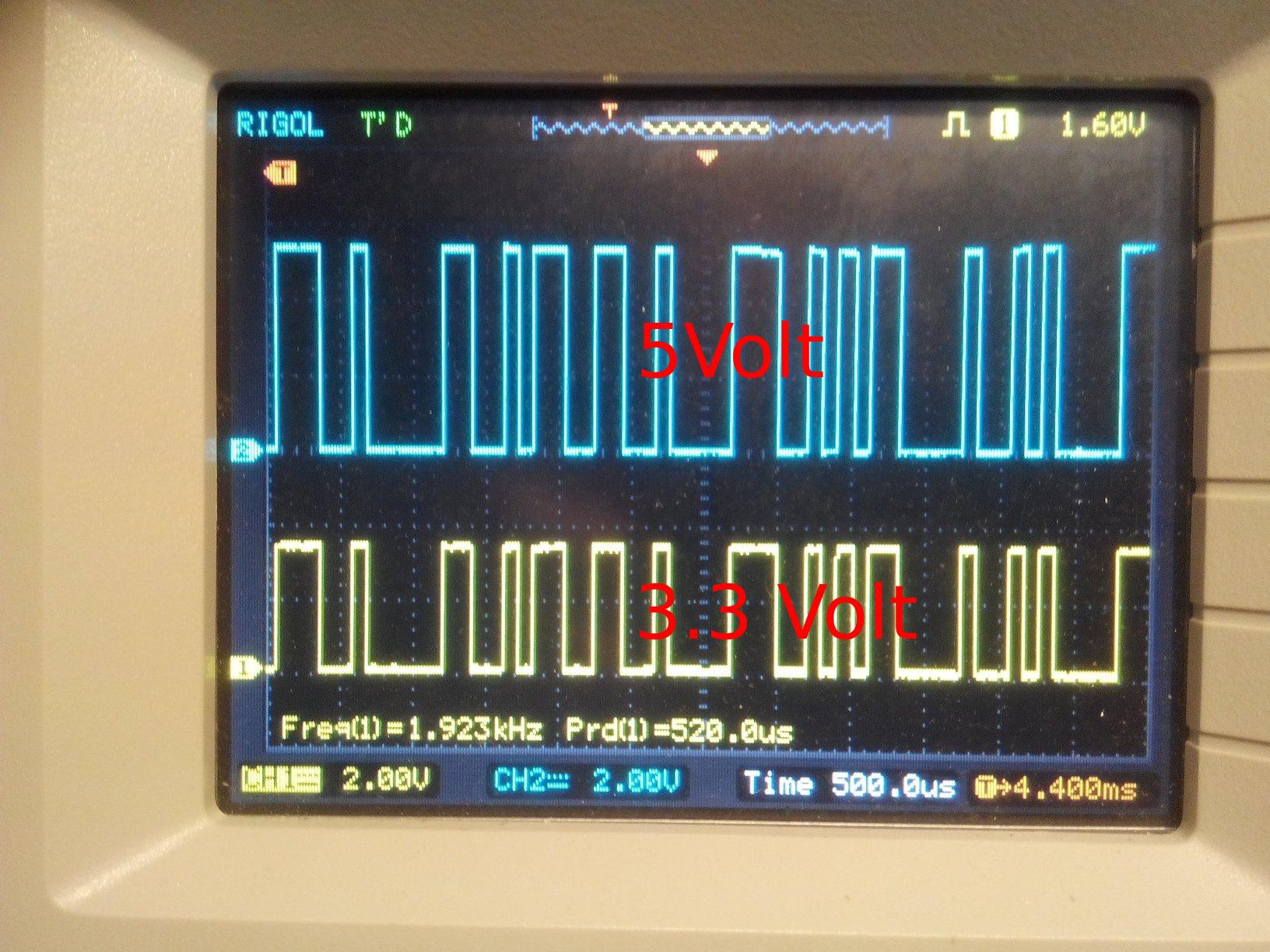
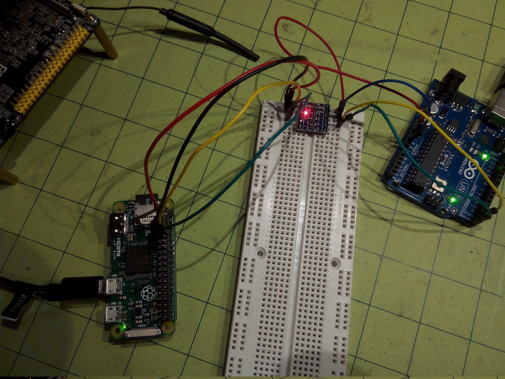
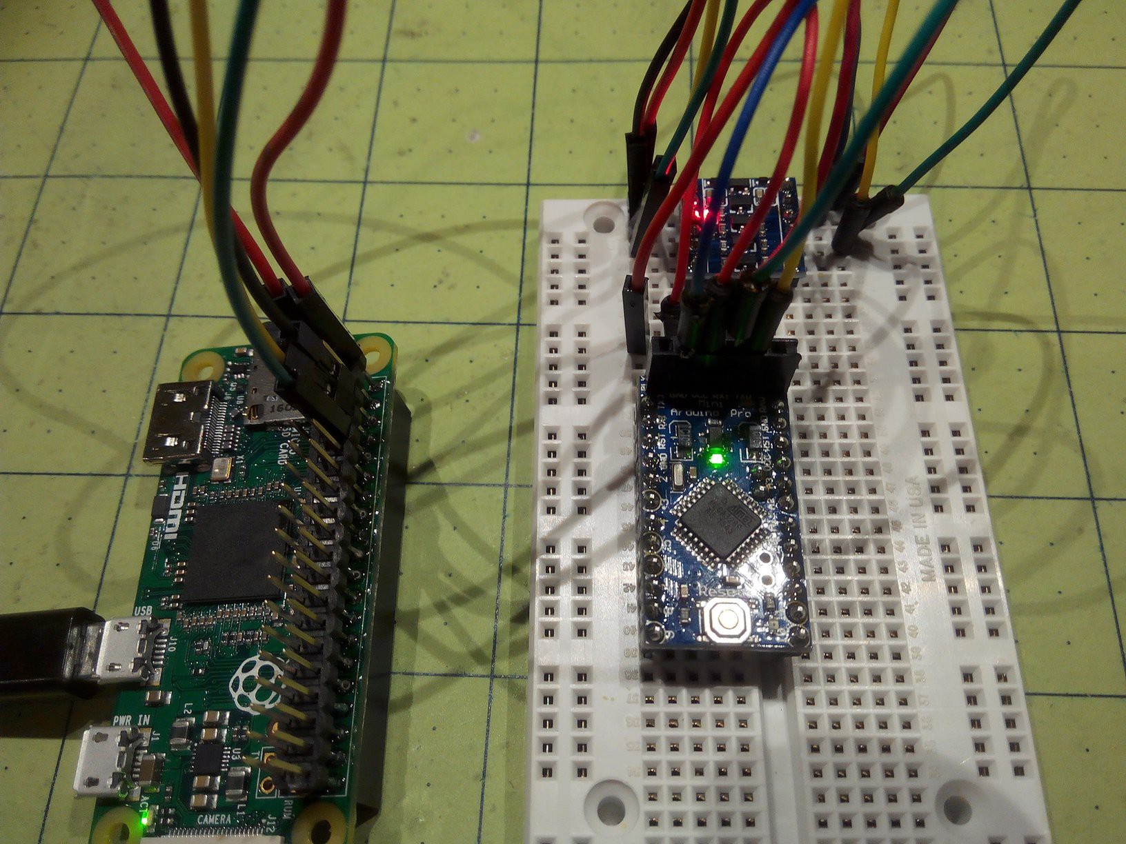
07/15/2016 at 02:52 • 0 commentsCan we save power by using a direct serial connection between the Ardunio and the Pi, rather than the USB cable that requires an extra serial-to-USB converter? We will need a level shifter to convert the Arduino 5Volts to the Pi 3.3 Volts. It definitely helps to have an oscilloscope to see if the serial transmission is going through to the other side:
![]()
Works with the Arduino UNO and the Arduno Pro Mini.
![]()
![]()
The power consumption is between 1.3W and 1.5W.
![]()
-
Going Raspbery Pi Zero
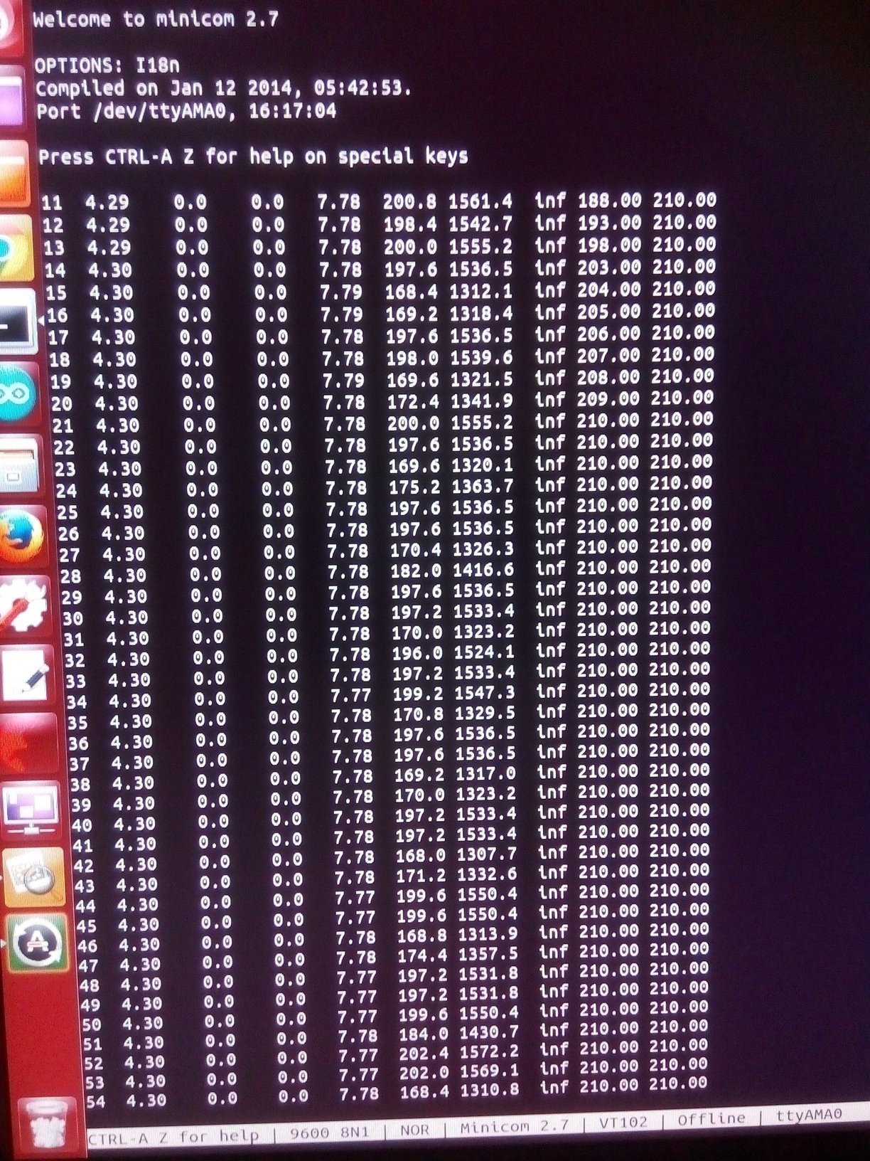
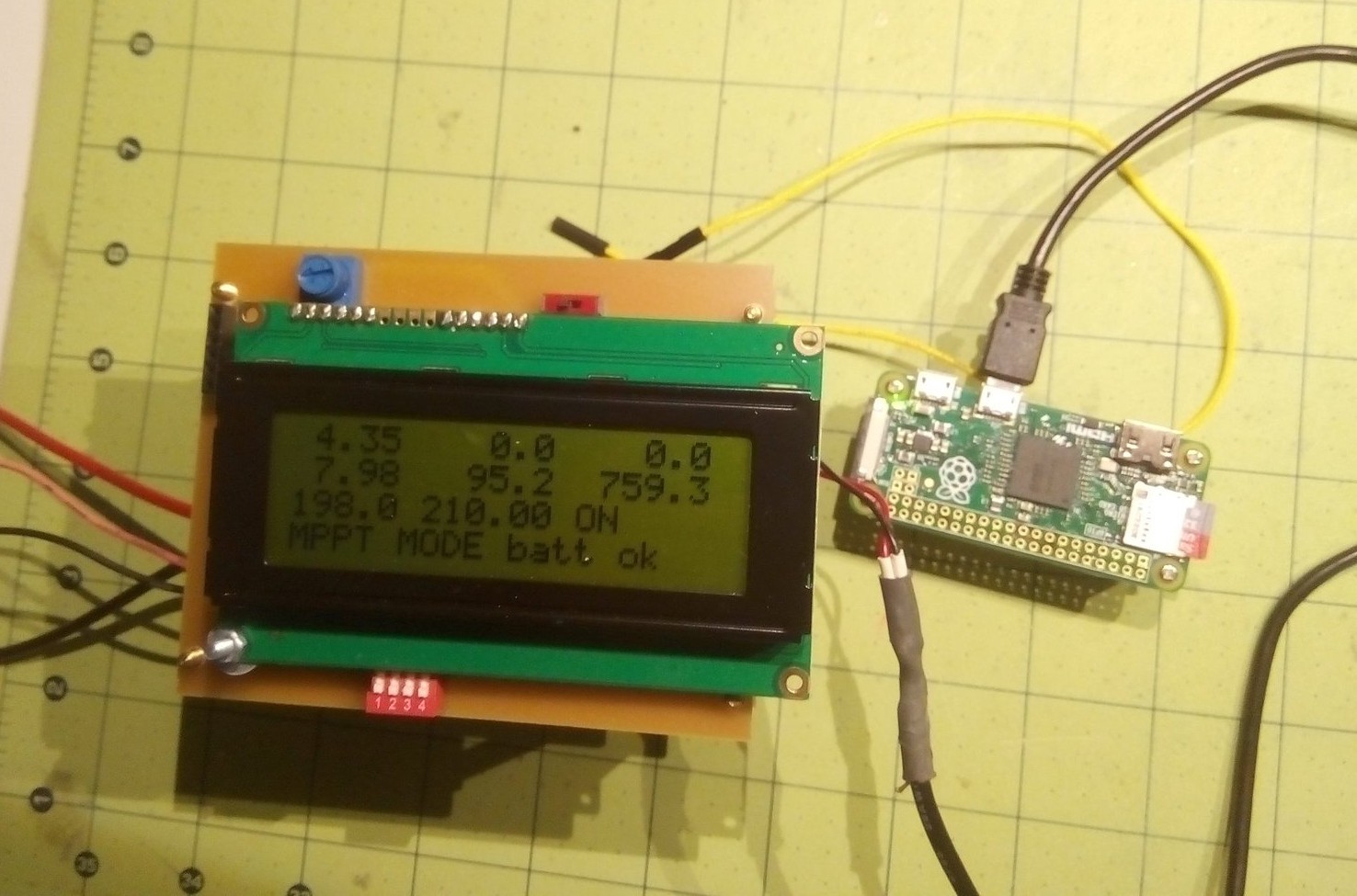
07/13/2016 at 23:23 • 0 commentsAccording to this Wiki article https://en.wikipedia.org/wiki/Comparison_of_single-board_computers#Physical_and_electrical_comparison, the Pi Zero is the lowest power consuming single-board computer at about 0.5W idle. A first test confirms that: 250mW for the charge controller plus 500mW for the Pi = 750mW (reading is 759mW.)
![]()
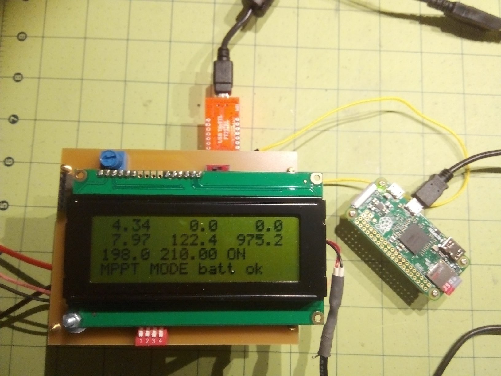
For USB communication between the Arduino and the Pi, we need to add a serial-to-USB adapter which results in 975mW power draw.
![]()
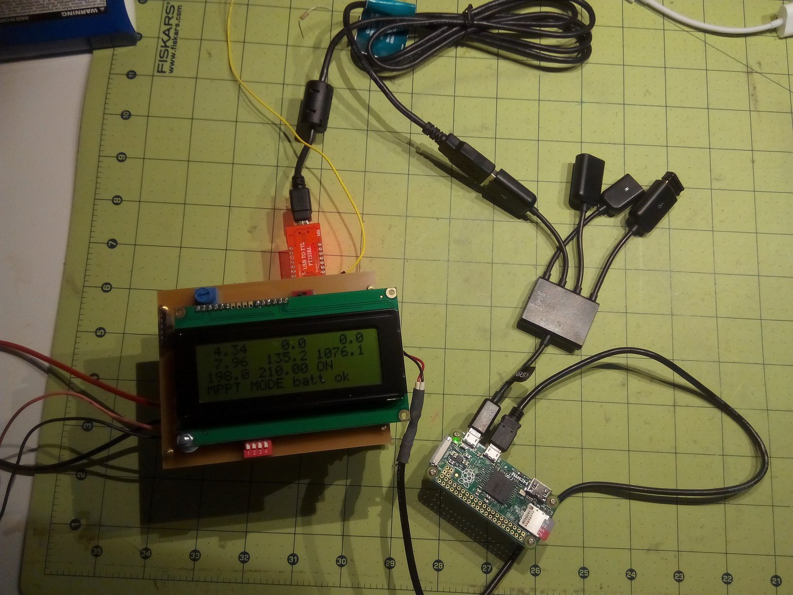
A USB hub to add a few USB ports adds another 100mW to 1076mW. (The Wifi adapter in the picture is not powered yet.)
![]()
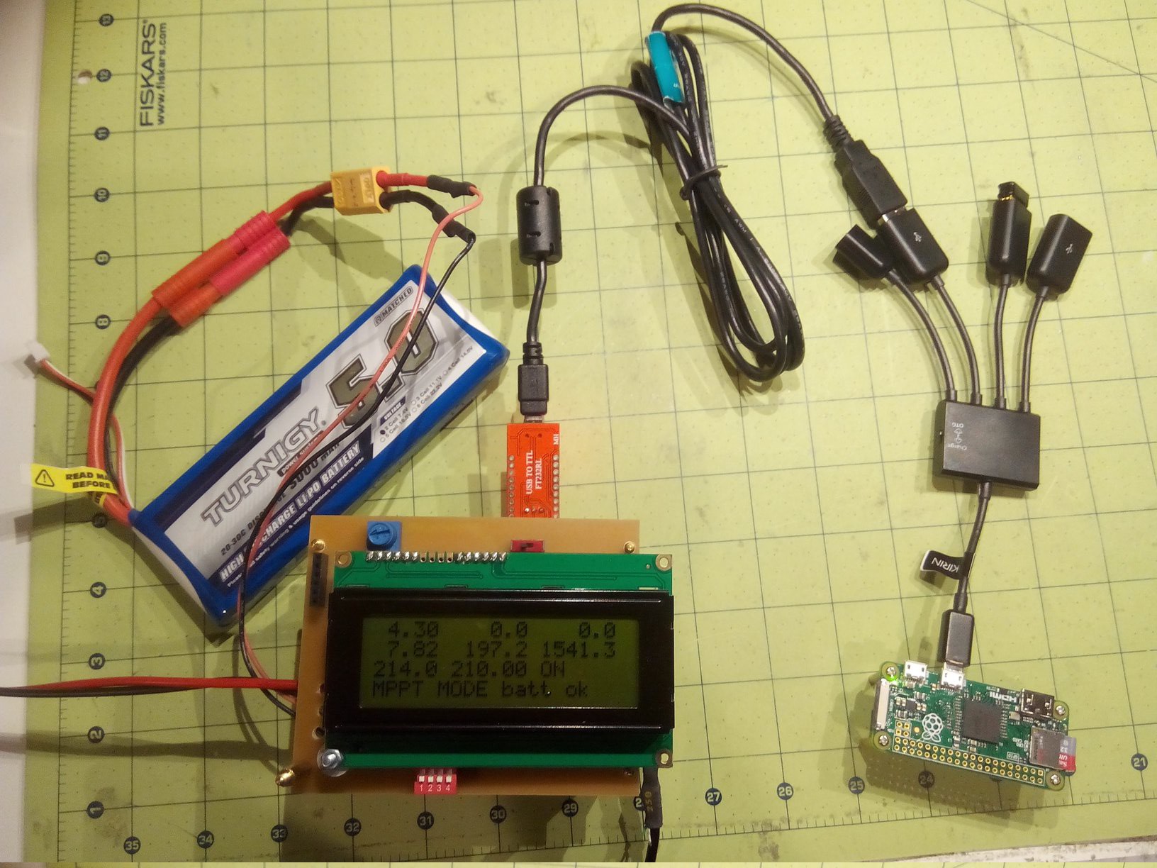
With the Edimax Wifi adapter powered up and connecting, the power goes up to 1541mW.
![]()
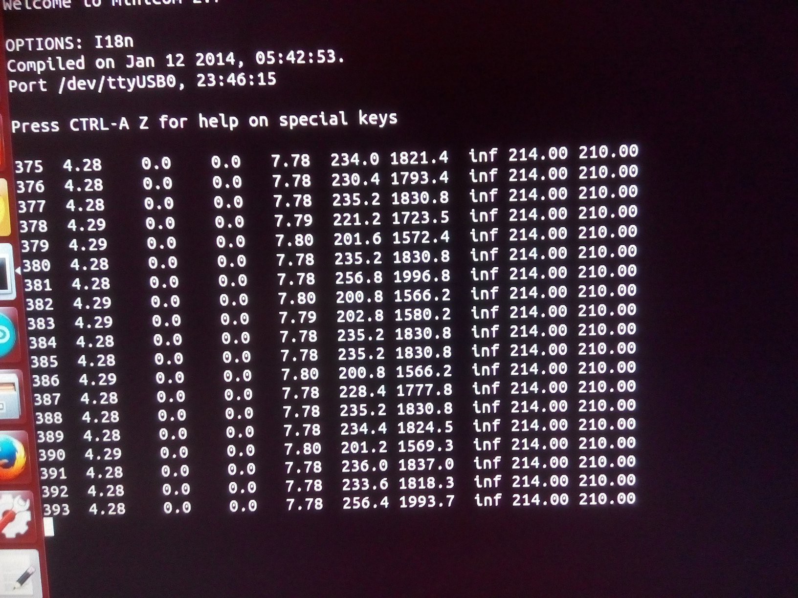
When we run minicom on the Pi, the power fluctuates between 1.5 and 1.8Watts.
![]()
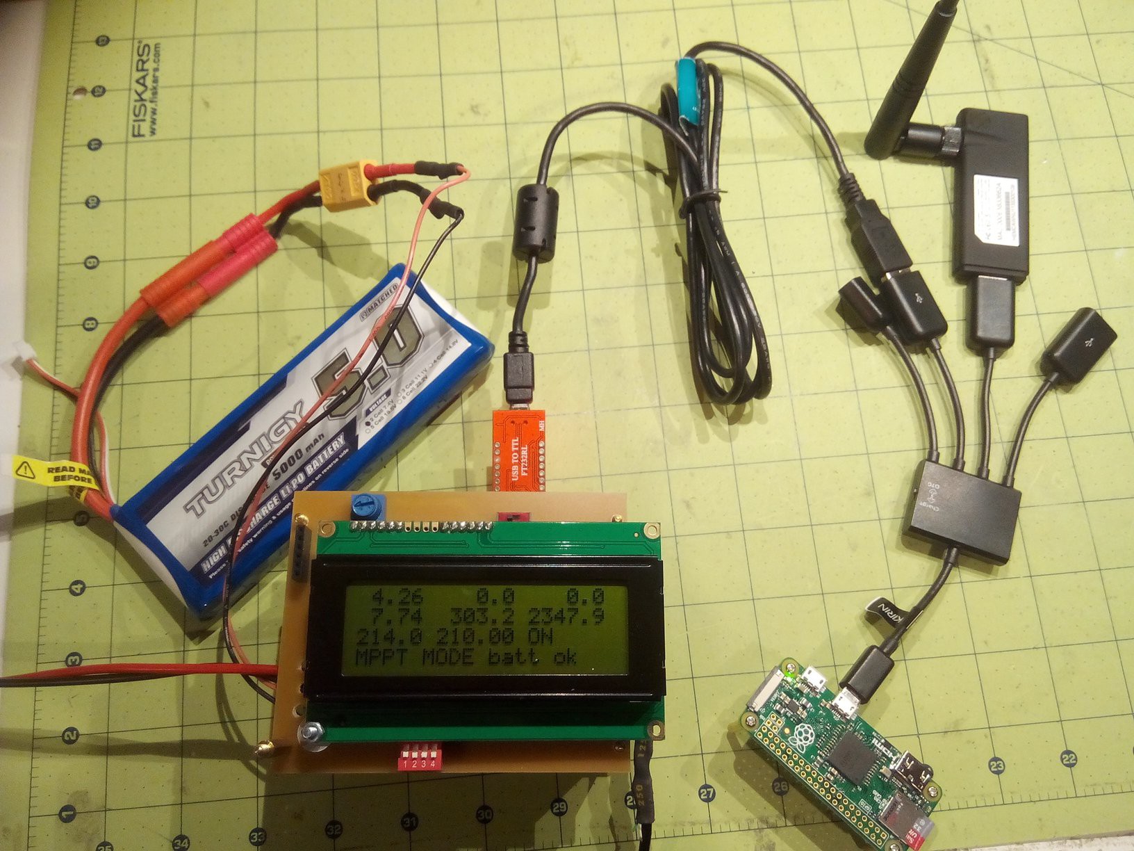
The more powerful Hawking Wifi adapter with the antenna has a much better connection, but it also uses more power (system power = 2346mW) than the Edimax.
![]()
-
Powering a Pi Computer and Arduino-Pi Communication
07/11/2016 at 23:52 • 0 commentsUltimately, the goal is to power a Pi-based computer with this charge controller. The Pi will then communicate through Wifi (or a cellular data connection) with the user and do more complex tasks, such as running a web server, etc. And since I already have an Arduino in the charge controller that monitors the solar panel and battery, I can now send the power data from the Arduino to the Pi. This can be used to let a remote user retrieve power status and for a clean shutdown of the Pi on low battery.
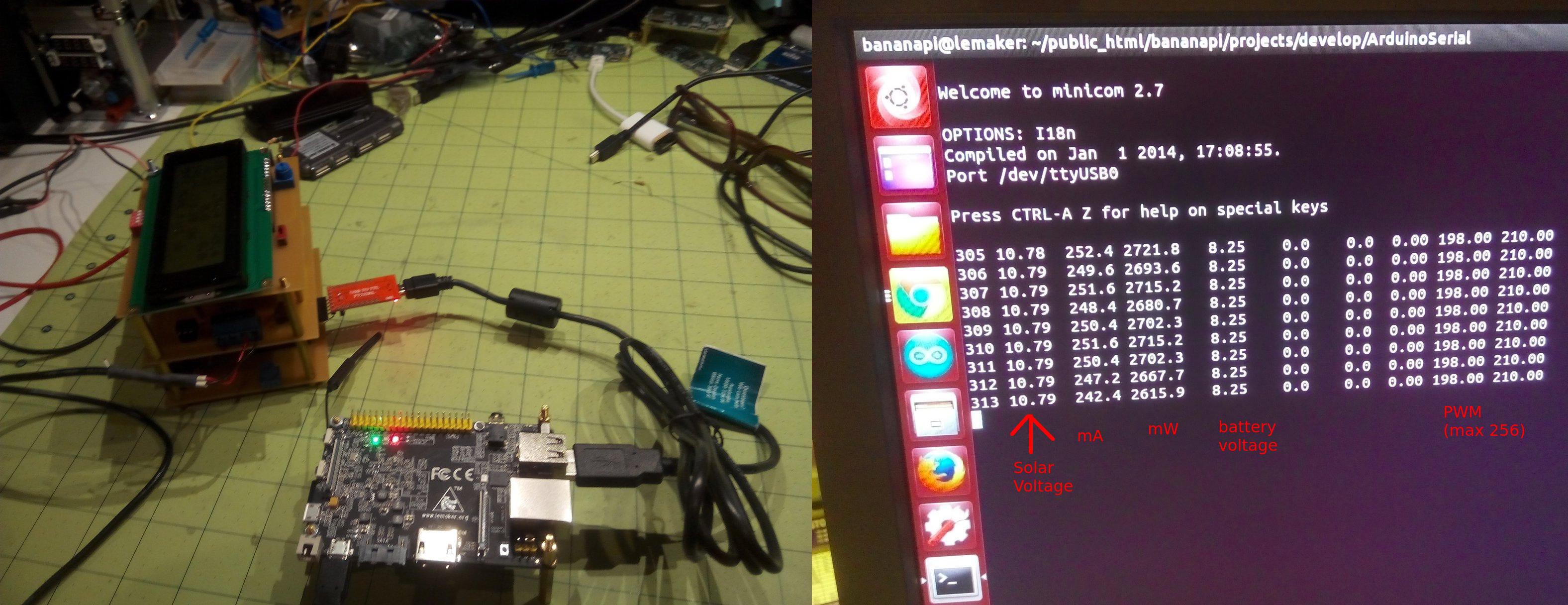
Initially, I used a Banana Pi (almost same as Raspberry Pi) but the power consumption seems a bit high. In the simplest setup where the Aduino and the Pi communicate through a USB cable, the Banana Pi (actually Pro) uses about 2.7 Watts.
![]()
-
Solid State Relay saves another 40mW
06/09/2016 at 20:56 • 0 comments![]()
I have been working on ways to reduce the power that the solar charge controller draws without charging the battery or powering loads. The SSR brings the coil current down to 1.7mA with a 2.2K resistor on the Arduino output. That's about as low as I think you can get it. On the relay output side, the system can power a Banana Pi (or Raspberry Pi) through the relay without problems. The relay is a Panasonic AQV252G.
![]()
-
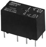
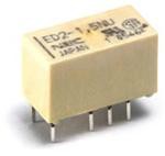
New Relay Saves 100mW
05/28/2016 at 00:13 • 0 comments![]()
![]()
![]()
![]()
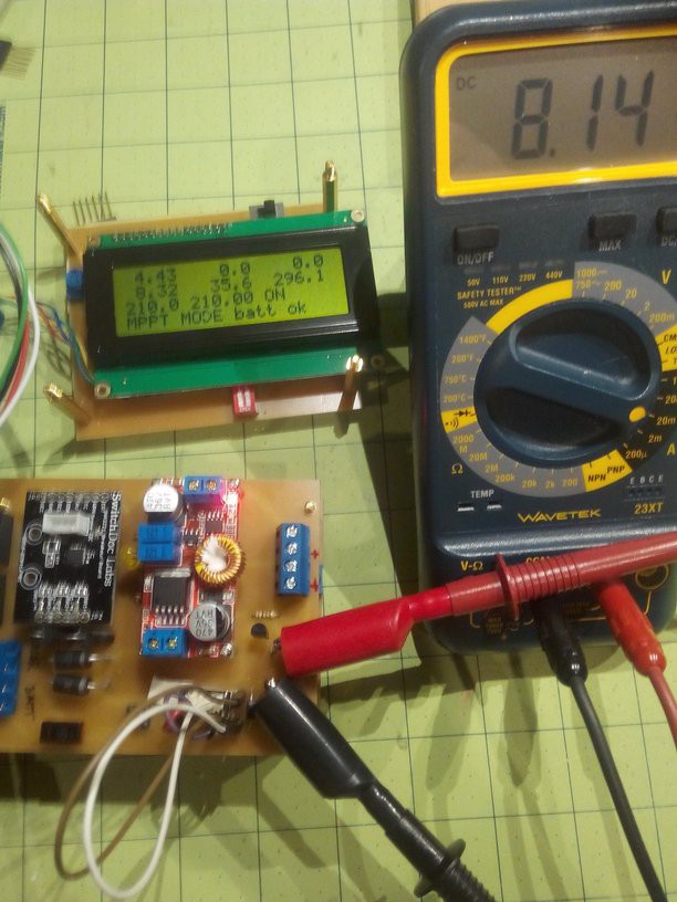
Relay current: 24.3 mA
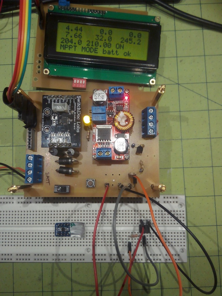
System power: 408.3 mWRelay current: 8.14 mA
System power: 295.1 mWWith the new relay, the power consumption of the system on battery power is under 300mW. The purpose of the relay is to make sure that when the system has turned itself off, no leakage current discharges the battery over long periods of storage. So it only uses power when enough solar power or battery charge are available.
Since the new relay pulls so few mA, I tried to run it directly from the Arduino port, but strangely, the system uses less power with the transistor than without! So the transistor stays.
Arduino MPPT Solar Charge Controller
The charge controller consists of a buck converter that is controlled by an Arduino via a half-bridge driver.