Lex Kravitz
-
3D printing tips
10/06/2018 at 16:54 • 0 commentsThis log will cover 3D printing tips. If you have suggestions from your own experience please leave them below!
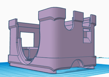
FED3 was designed to be printed with minimal support material, as our printers don't have supports. You'll notice that many of the parts "slope up", which allows them to be built without any supports.
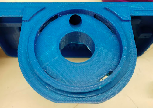
FED3 is a mechanical device, and the quality of the print will affect its reliability. One of the biggest issues we've experienced with FED3 are pellet jams, which can be caused by imperfections in the print. We print FED3 parts at a slow speed of 40mm/s and a layer height of 100microns. This takes about 24 hours of total print time to produce one FED3. The front plate takes about 10 hours but these settings make very smooth surfaces for dispensing pellets.
We print much faster while we are prototyping. Here are some examples of different print settings and potential issues that occurred below:
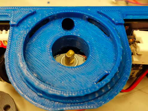
200 micron layer height, 40mm/s (~4 hours to print front plate). Print is OK but has some rough areas:
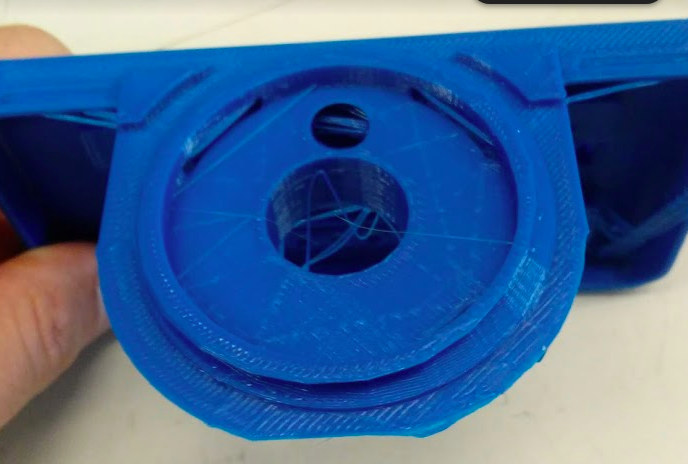
200 micron layer height, 100mm/s (~2.5 hours to print). Many problems!
-
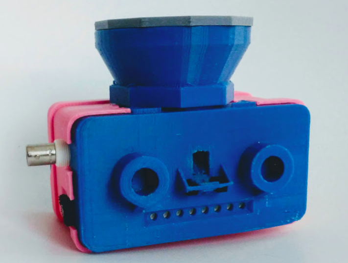
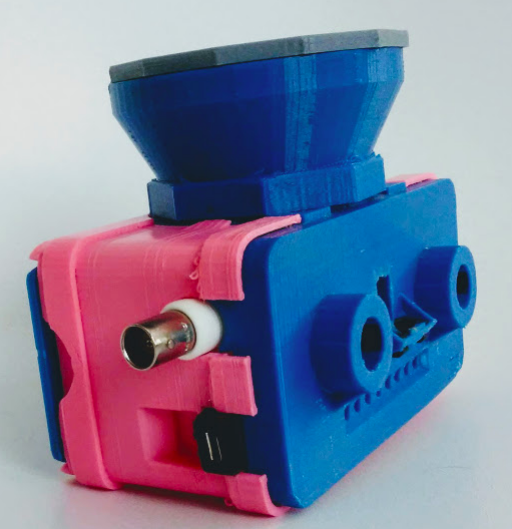
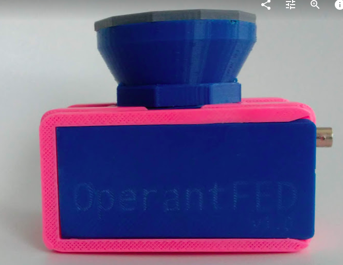
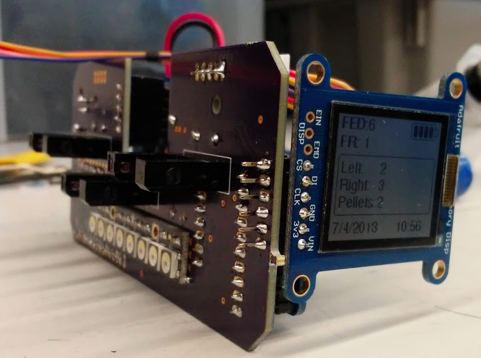
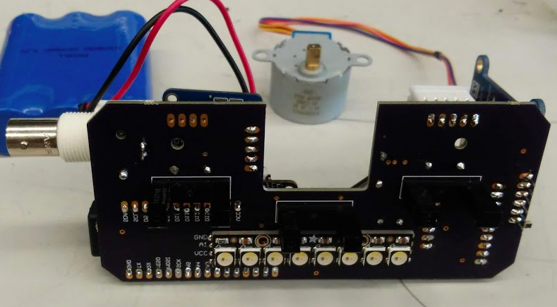
First complete build!
08/15/2018 at 15:45 • 0 commentsWe have finished the 3D design and assembled the first two operant FEDs! Stay tuned for validation data, but for now, some photos!
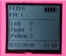
Screen displays behavioral data, timestamp, and battery life:
-
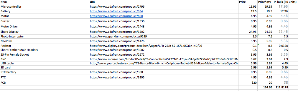
Price breakdown / BOM
08/15/2018 at 14:42 • 0 commentsMohamed prepared this BOM (spreadsheet in files area). Operant FED (not including 3D printing) is ~$135 each, but that can drop to ~$110 in bulk with price breaks on components.
-
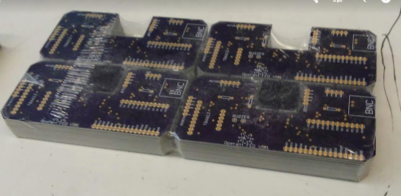
50 PCBs!
08/15/2018 at 14:38 • 0 commentsThis showed up today! We're getting to work populating these!
-
PCB v5 - done!
07/08/2018 at 16:09 • 0 commentsThis is the final version! It seems to work well, we may just update the orientation of the buzzer, but otherwise all systems are go! Video coming soon...
-
PCB v4 - almost there!
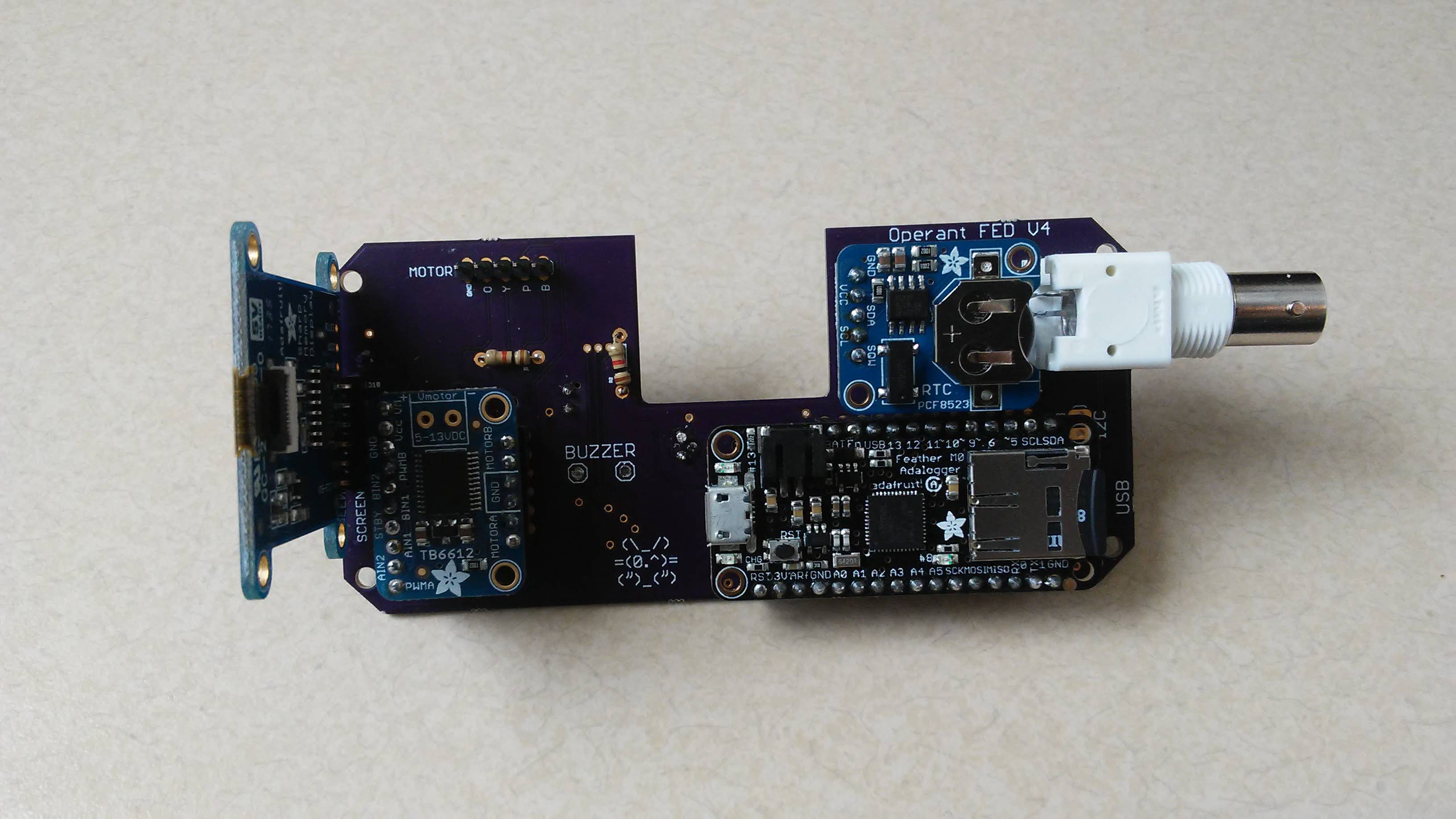
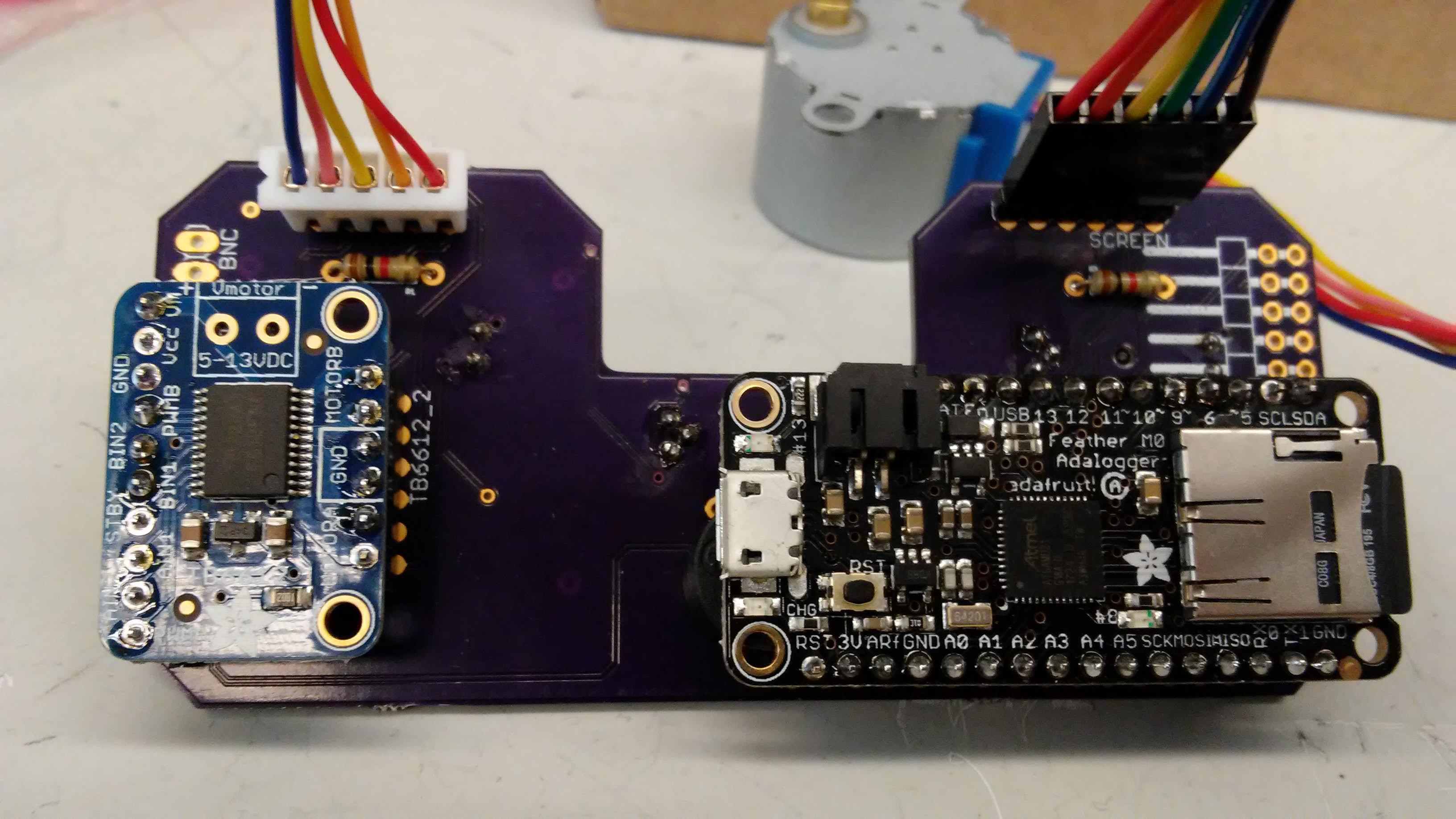
06/20/2018 at 17:41 • 0 commentsWe skipped right over PCB v3, and our v4 version is much easier to wire up, as we mounted the display and the BNC output directly to the PCB. We also coded up some control code that runs 4 programs: a free-feeding program, FR1, FR5, and a progressive ratio feeding program. See start screen video below :)
![]()
![]()
-
PCB v2 video demo!
05/26/2018 at 17:37 • 0 commentsVideo demo of populated operant FED PCB v2 in operation
-
PCB Round 2 testing complete!
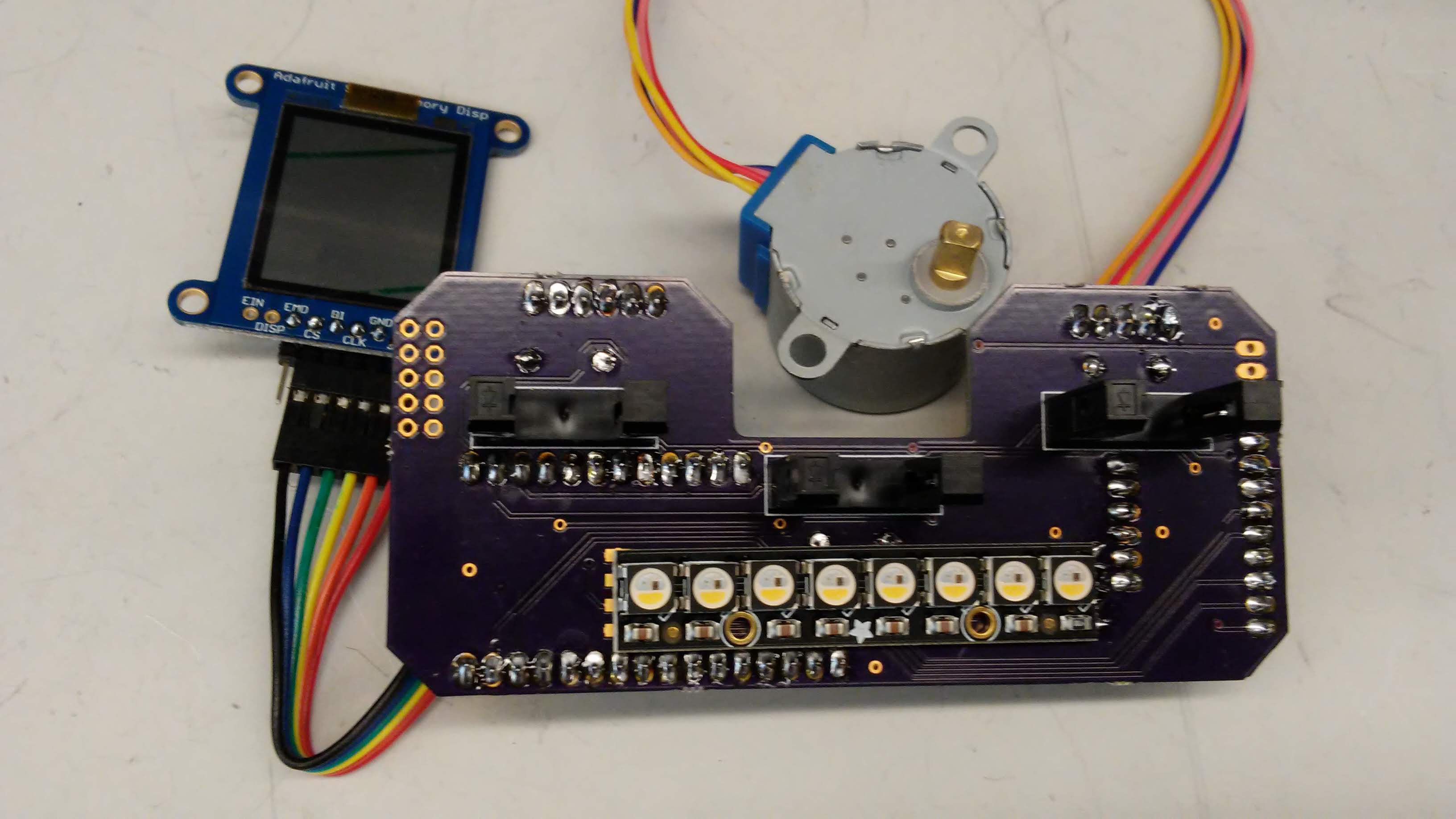
05/24/2018 at 12:08 • 1 commentMohamed populated the new PCBs over the last week and they are working great! To recap, these boards include:
- Three Sharp Photo-Interrupters (2 will be operant "pokes", and one will be used to detect pellets that are dispensed
- One stepper motor controller and 5V stepper motor for moving the pellet dispensing disk
- One Sharp low-power memory LCD display
- One 8 LED Neopixel strip
- One beeper for auditory feedback
- One Feather Adalogger M0 board to control the device and save data
The idea for this improvement to FED2.0 is that this will be a true "platform" device, that can be flashed with different code to function differently. So one code can make it act like FED2.0, while other code can deliver more complex operant paradigms for training mice.
We confirmed that all hardware on this PCB rev is operational, but (of course!) we want to make a couple tweaks before we mass produce. We want to make it a bit easier to solder - a couple components were too close, and we want to move the location of the screen. Overall this will provide a lot more functionality than FED2.0, while being much easier to assemble and taking up ~1/2 the space!
![]()
![]()
-
PCB round 2!
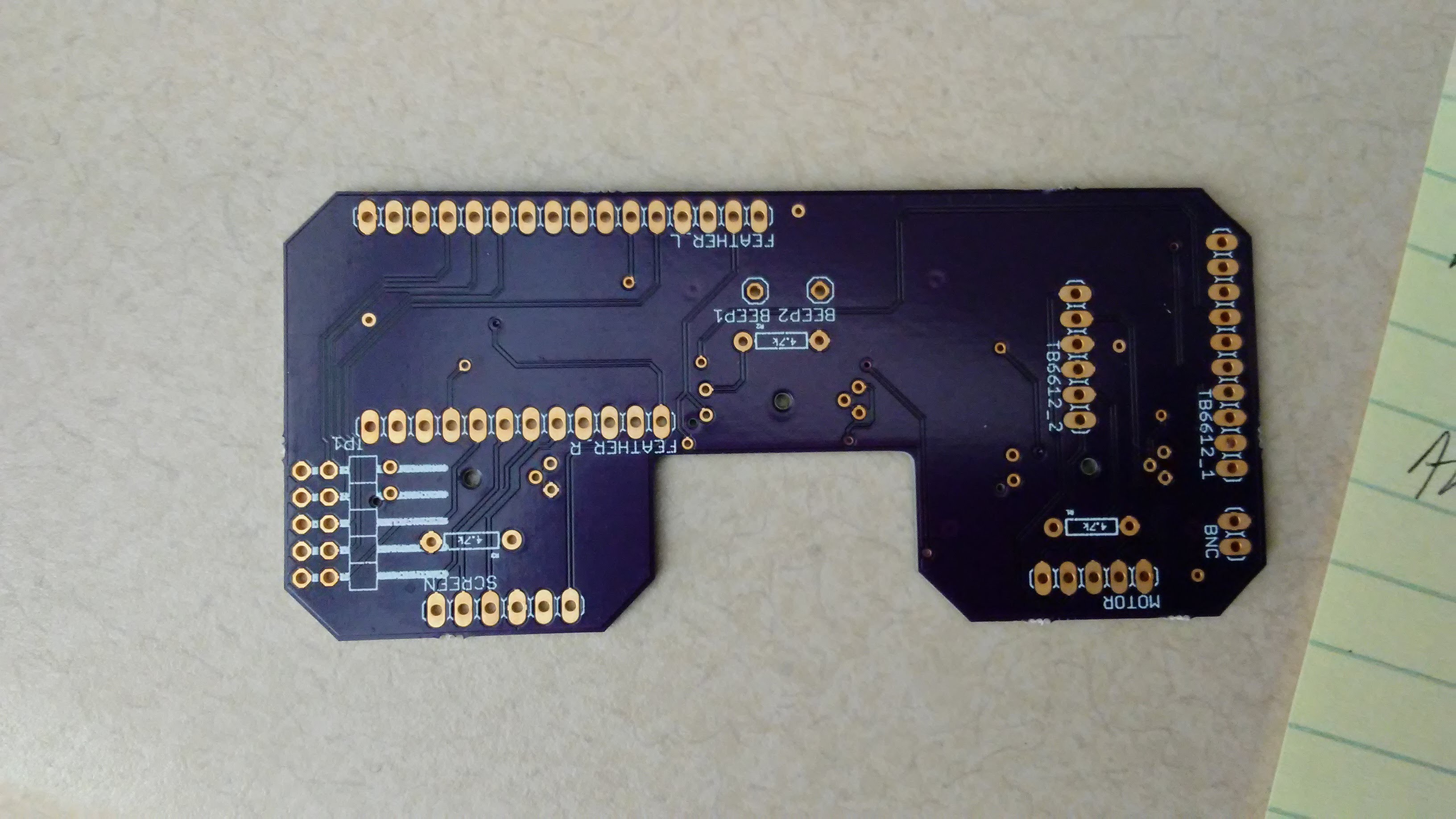
05/10/2018 at 19:19 • 0 commentsJust got the new PCB... stay tuned for results!
![]()
-
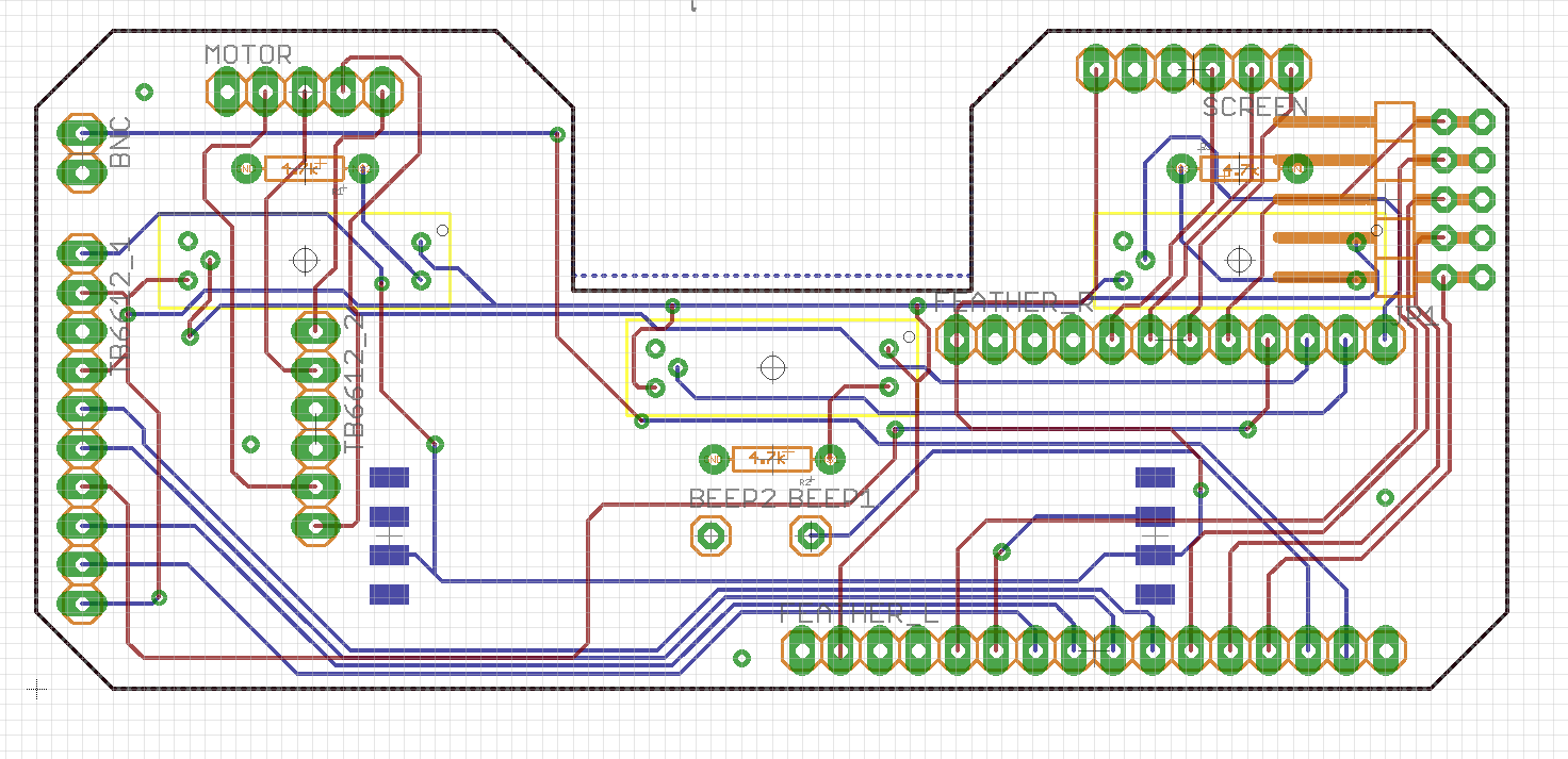
PCB update
04/25/2018 at 23:41 • 2 commentsWe wrote a simple code that tested the micro-controller's GPIO connections with sensors/actuators. All of the following connections were fine: 3 photo-interrupters, BNC, motor driver, motor headers, screen header, and buzzer. The Neopixel strip was fabricated in the wrong orientation, so I soldered three wires and manually tested it. Consequently, we updated our PCB by carrying out the following:
1) Mirrored all 3 IR sensors and rewired them, in order to operate them on the front side of the board
2) Mirrored Neopixel strip and rewired it in order to solder it to the front side of the board
3) Added 2x5 headers that connect to 4 digital pins, 1 analog pins and of 5 ground pins. These will be utilized for further prototyping/communications with other periphery.
4) Changed the board size and shape in order to improve its fit with already existing FED base.
5) Changed the location of the beeper for a better fit.
The board is ready for fabrication, however, next up: we will be adding a logo to our design!
![]()
Feeding Experimentation Device 3 (FED3)
Version 3 of our home-cage feeding device, FED. FED3 includes nosepokes and stimuli for behavioral training.