Before starting with building anything you should make sure your computer can communicate with the Adalogger M0 board and that you can flash the operant FED sketch. Start by installing the Arduino IDE.
2
Install relevant Arduino boards to run the Adalogger M0
The Adafruit M0 Adalogger board is not natively supported by the Arduino IDE. To enable the Arduino IDE to flash sketches to this board, follow instructions here.
Note: There is an incompatibility between the FED code and Adafruit SAMD board packages >1.5.5. We don't know why, but while we try to figure it out, just install version 1.5.5 of the Adafruit SAM Board package.
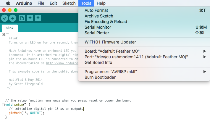
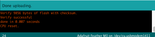
After completing these steps make sure you can flash the example sketch "Blink" to the Adalogger board before continuing. Open Blink in File>Examples>Basic>Blink. "Double-click" the button on the Adalogger to put it in bootloader mode and make sure Board is set to "Adafruit Feather M0" and port is set to the same before clicking upload (the right arrow at the top of the Arduino IDE).
You should see "Upload complete" in the bottom feedback window and the red LED on the board should blink once per second.
Congratulations, you have configured your Arduino IDE and uploaded a sketch to the Adalogger!
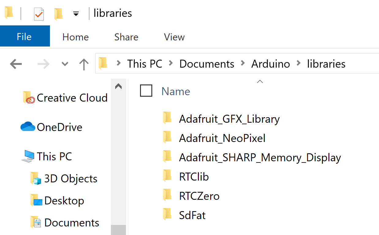
You can install them in multiple ways, but the simplest will be to download the prepared zip file (FED3libraries.zip from the files area). Extract these libraries to your Arduino libraries directory (for most it will be: /Documents/Arduino/libraries
When you're done they should all be in your libraries directory, see example:
NOTE: copy these libraries right into the Arduino/libraries folder, not inside another sub directory or the Arduino IDE won't find them. If this doesn't work, or you'd prefer a different way go through instructions here for how to manually add libraries.
4
Order the PCB
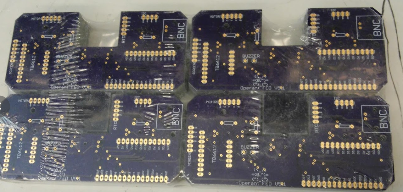
FED uses a custom printed circuit board (PCB) to minimize wiring and increase reliability of the electronics. The BRD file (what you use to order the PCB) is in the files area. Here's what 50 look like!
Order here (or download BRD file and order from wherever you like):
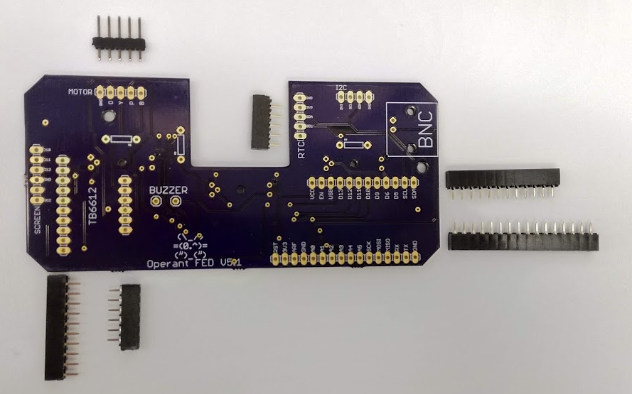
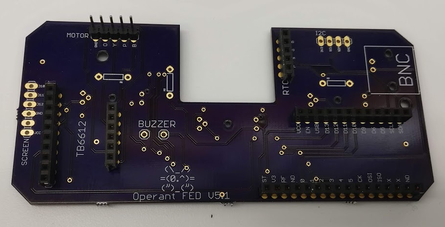
Start by soldering on all SIX headers. These include two short female headers for the Adalogger (one 12 pin, one 16 pin), a short female header for the RTC module (5 pin), and two short female headers for the TB6612 motor driver (one 10 pin, one 6 pin). Finally, solder one male header for the motor (5 pin).
IMPORTANT! Solder all of these onto the BACK of the PCB, the side that says Operant FED V5.1 and BNC.
Next solder the three PhotoInterrupters so they poke out of the FRONT of the board:
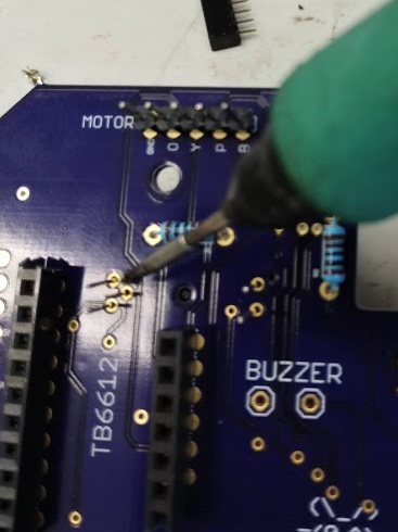
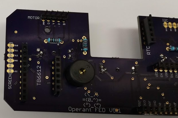
These each have an associated 1KOhm resistor, solder these onto the BACK of the board (blue resistors in photo below).
Solder buzzer into place and trim PhotoInterrupter and resistor wires:
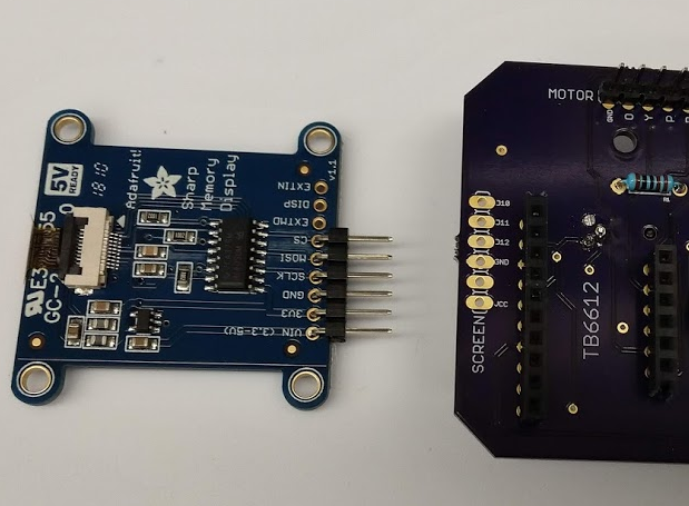
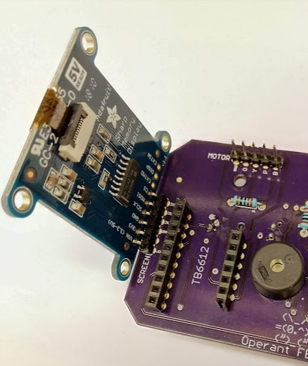
Solder 90 degree headers onto the Sharp Memory screen breakout and solder onto the board
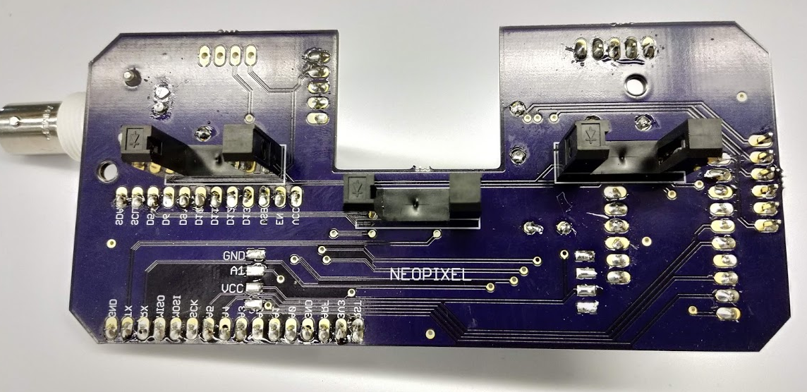
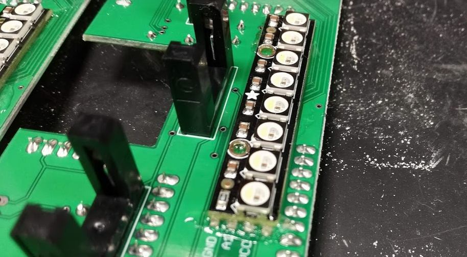
Solder the Neopixel strip onto the front of the board. This step is actually pretty difficult to get right, I have 2 approaches for doing it:
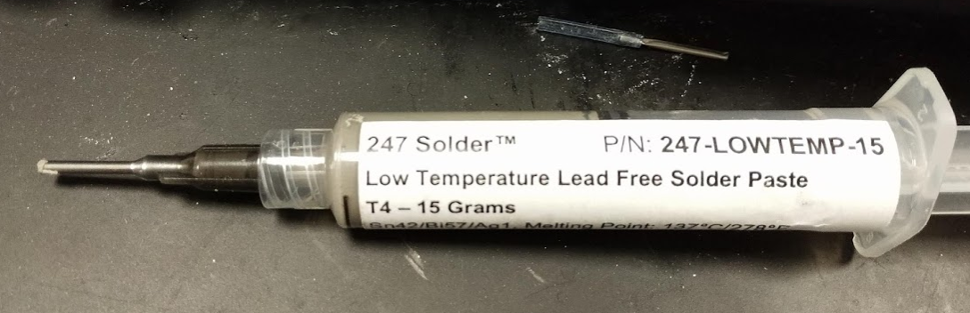
a) (newer) Use a low temp solder paste like this, and apply a ***tiny*** drop to each Neopixel pad on the PCB:
Then carefully place the neopixel and use a heat gun (one that can achieve >150C, we use this one: https://www.amazon.com/Heat-Gun-Vinyl-Heat-Shrink-Station-iHGun-1-Accuracy-Temperature/dp/B0752Z4165) to carefully heat up the PCB until on each side until you see it flow. After it cools, use epoxy to secure it in place, as it's pretty easy for the Neopixel to pop off if the FED PCB flexes at all during assembly.
b) (older method) Melt solder onto all 8 pads of the PCB and the Neopixel, place them together, and then use a super fine tipped soldering iron to melt each pair together:
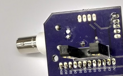
Final step for the PCB! Solder the large BNC connector to the board:
6
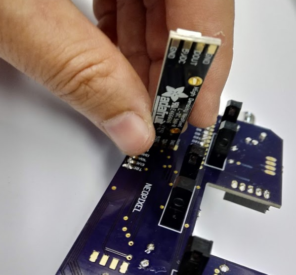
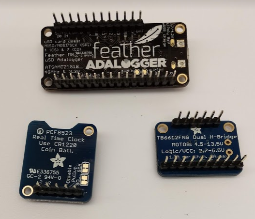
Solder headers onto Adafruit breakout boards
Solder male headers onto all 3 Adafruit breakout boards. Put the coin cell battery into the RTC breakout at this point.
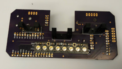
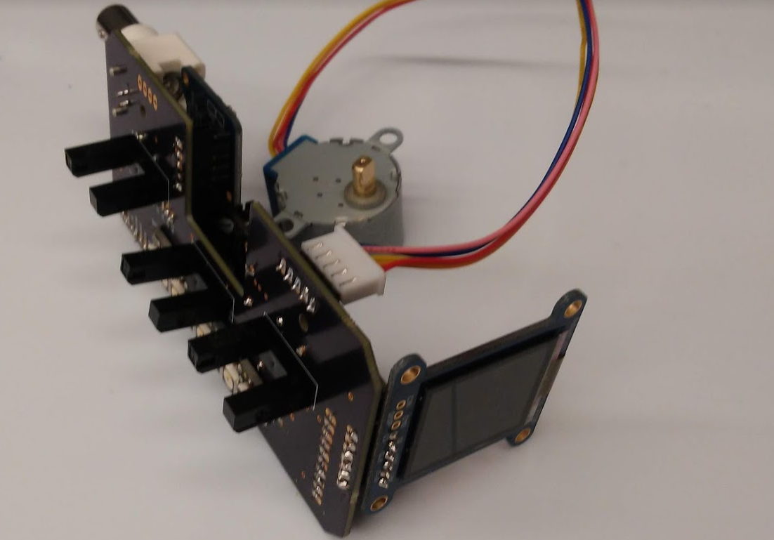
Plug these boards and the stepper motor into the PCB and you're done with the electronics!
7
Download FED3 sketch and flash FED3
Before assembling the device into the 3D housing, you should confirm that it works. Extract the latest FED3 Arduino Sketch (in the files area) and the sketch "FED3_SetClock_063019.ino" to where ever you like to keep Arduino sketches (for me it's: /Documents/Arduino).
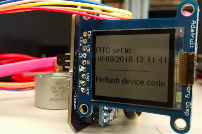
Open the FED3_SetClock_063019.ino sketch in the Arduino IDE and flash this code to the M0. You should see a message on the screen that the RTC was set correctly.
Unless you remove the coin cell from the RTC module (or if the coin cell dies after a couple years) you will never have to set the time and date again.
Next, flash the FED3 code. You should now be able to use FED3. At this point, make sure all electronics work, as it will be easier to fix things now than once it's inside the 3D housing. You will need to connect a battery to the Feather for the motor to turn.
8
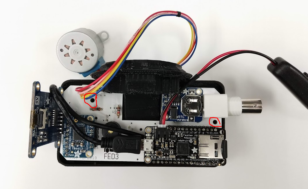
Hot glue the USB extension cable in place, and attach the power button and battery to the Feather.
Photos coming of these steps, but you want to hot glue the USB extension so it is accessible from the SD door, and attach the JST power button extension and battery to the Feather JST port.
9
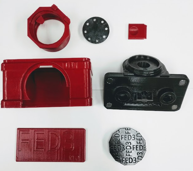
Print the seven 3D parts
If desired, glue the 8mm magnets and the metal nose into the front piece. (The part in the photo below has a "black steel" nose piece)
You can coat all of the parts in spray acrylic (don't go crazy here, one coat will do it!).
10
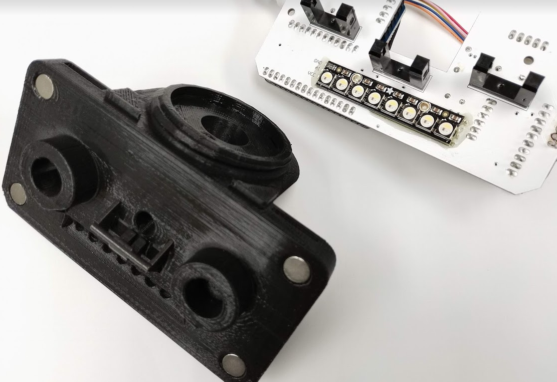
Mount the electronics in the 3D printed front piece
Seat the electronics in the 3D printed front and secure with 2 screws (noted with red circles below)
 Lex Kravitz
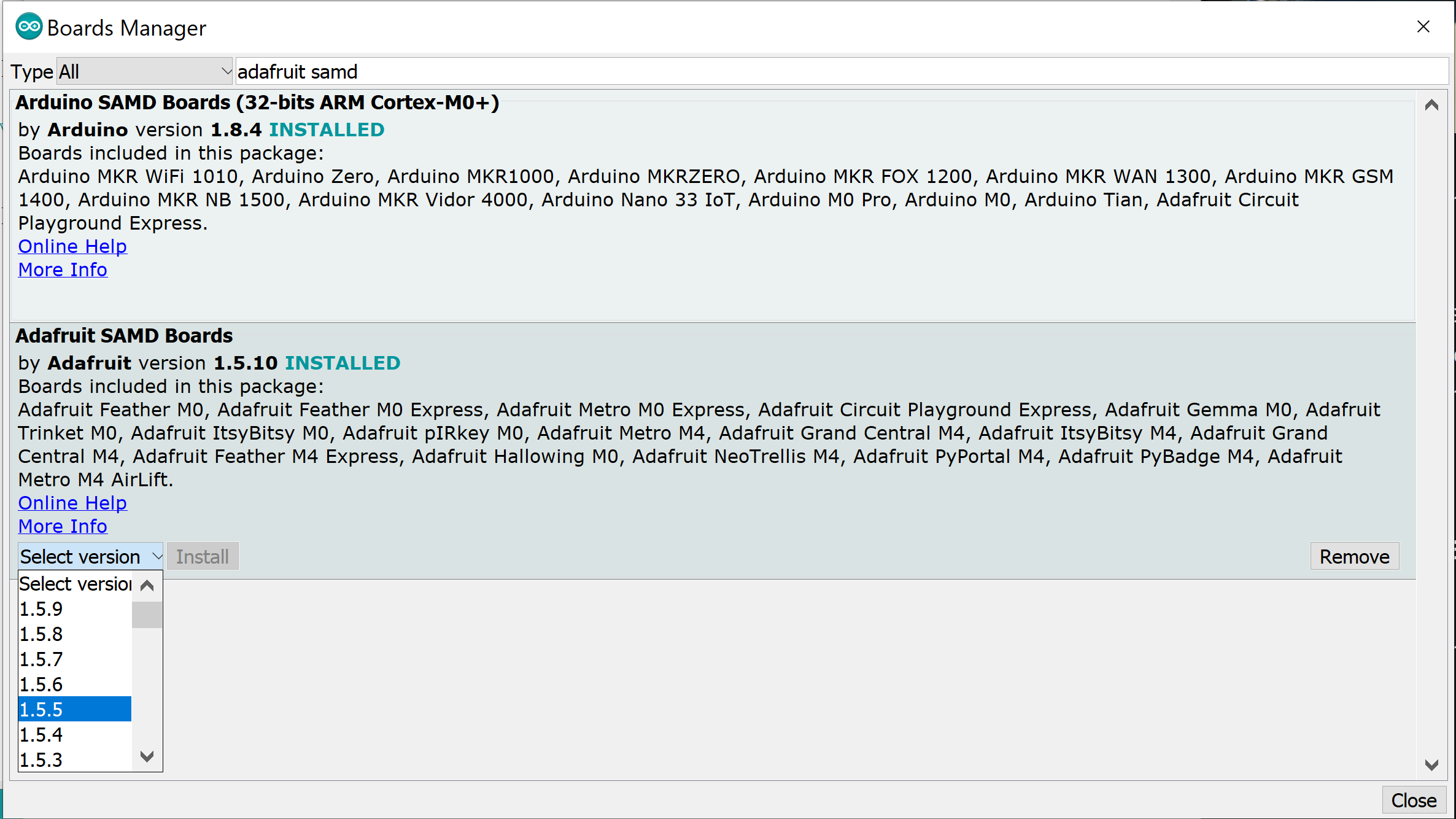

Discussions
Become a Hackaday.io Member
Create an account to leave a comment. Already have an account? Log In.