In the pursuit of authenticity, germanium diodes are being ordered, examined and used.
I already have some 1N60 from a Chinese eBay seller, just in cases I needed to do some fine signal detection (and to change from the Schottky)
Their forward drop tensions (in mV): 284, 281, 283, 281, 279, 280, 278, 282, 279, 280, 281.... pretty good.
What about the reverse leakage ? Voltages are measured across a 10K Ohm resistor when 9.82V is applied to the diode and resistor : 100µV/10K=10nA (my DMM can't resolve more and the readings decrease quickly)
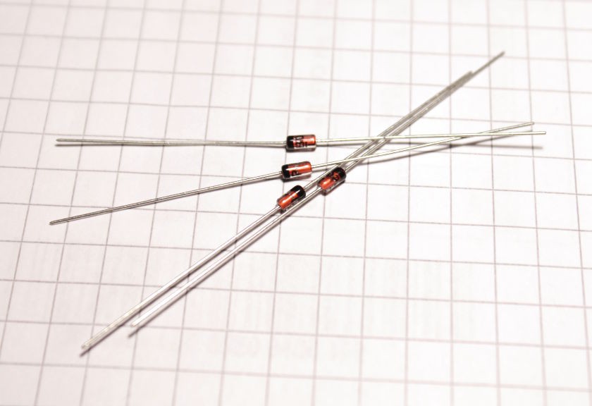
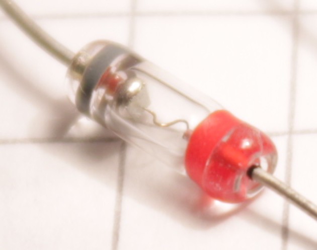
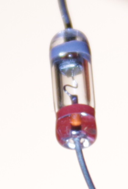
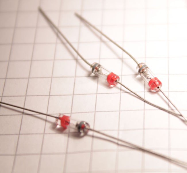
But the "look" of the 1N60 makes it too close to a vulgar 1N4148... Why make a special circuit if it doesn't look special ? So I got myself a little lot of Д9Б (pronounce D9B because it's russian) and their larger glass package lets you see the spring-y point-contact structure. Awesome :-)
I measured the following forward drop voltages (in mV) : 278 286 271 288 255 264... It's less consistent, more scattered, I should expect from 0.2 to 0.3V of drop (this depends of course on the current).
What about the reverse leakage ? Across the 10K resistor I read (in mV): 23, 30, 28, 53, 34, 50, 29, 24, 36, 34... So I have to expect up to 0.5µA of leakage (at 9V). That's 2 orders of magnitude leakier than the 1N60 but still way less than a Germanium transistor...
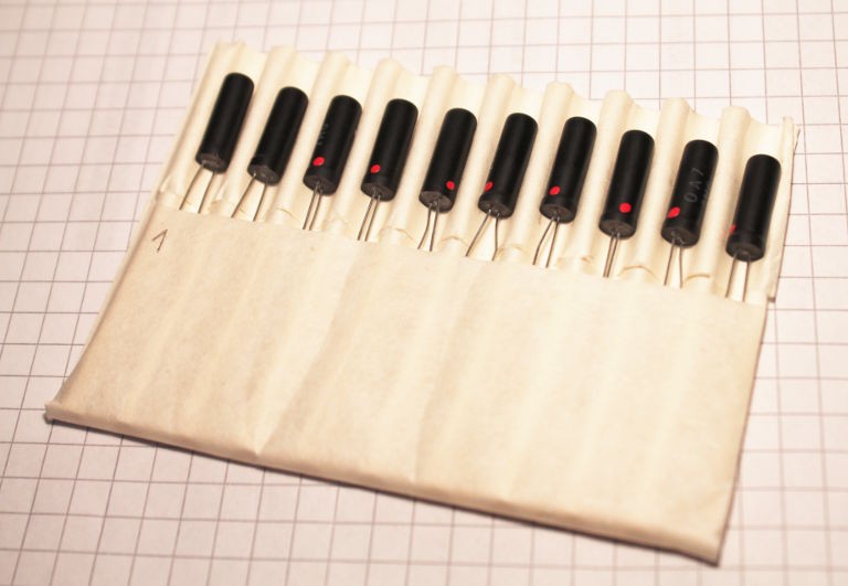
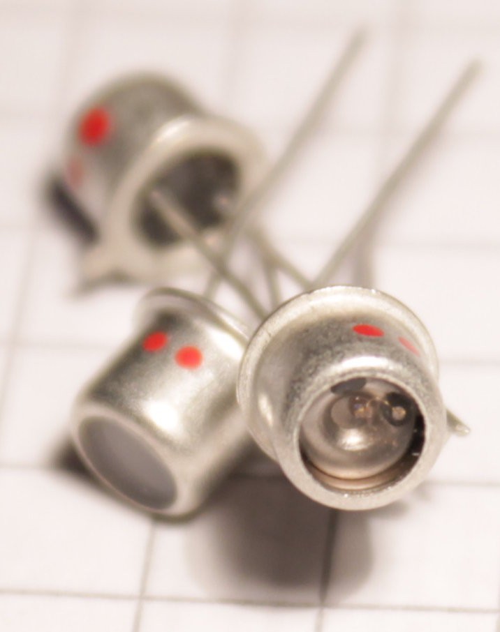
But wait, the pursuit does not stop there. On the Internet, there is a smal (monetary) line between funky and spooky. I got some crazy looking OA7 diodes and the untrained eye wouldn't know what this 2-legged thing is. "Is this an antique capacitor ?" Awesome ;-)
I got 10pc OA7 (yet). Don't they look cute ? Like they are sleeping in a very wide bed...
I measured the whole lot's characteristics:
| n° | drop (mV) | Leakage (µA) |
| 1 | 242 | 1.6 |
| 2 | 245 | 1.31 |
| 3 | 236 | 2.09 |
| 4 | 234 | 1.61 |
| 5 | 237 | 1.60 |
| 6 | 240 | 1.63 |
| 7 | 243 | 1.30 |
| 8 | 238 | 1.16 |
| 9 | 244 | 1.34 |
| 10 | 232 | 2.27 |
The drop is lower than the others. This is balanced by a higher leakage, up to 5× the D9B. This is yet a, probably, a better detection diode.
I have once found Philips-made diodes with ultra-low forward-drop voltage for analog detection purposes but they are too modern ;-)
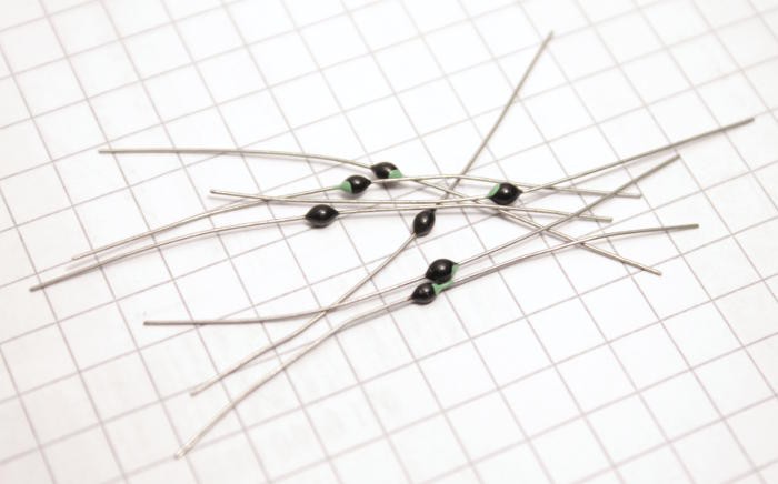
I also found in my archive 40 tiny bead-like diodes. They are pretty and quite unique so they might be used as well, despite being Silicon-based ;-)
More diodes should arrive (D311, more OA7, maybe OA9) and they will be tested as well but there is something else I have to do !
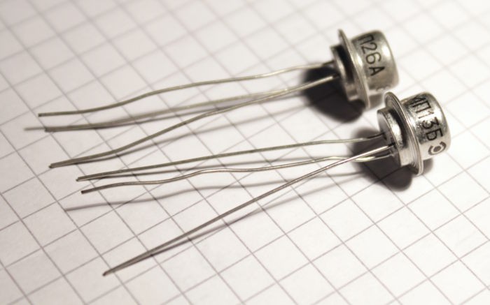
I had bought the first Ge transistors lots because I want(ed) to use them as double diodes... There would be less wiring to do when I want to reset 2 flip-flops with the same signal. So let's see if this works.
I got some МП13Б (MP13B) :
| n° | Vf1 (mV) | Vf2 (mV) |
| 1 | 186 | 196 |
| 2 | 202 | 189 |
| 3 | 194 | 201 |
| 4 | 206 | 196 |
| 5 | 203 | 192 |
| 6 | 203 | 191 |
| 7 | 202 | 190 |
(I didn't care about collector/emitter order but they can be guessed by whichever is higher by 10mV)
and МП26А (MP26A):
| n° | Vf1 (mV) | Vf2 (mV) |
| 1 | 180 | 170 |
| 2 | 193 | 180 |
| 3 | 194 | 185 |
| 4 | 187 | 177 |
| 5 | 185 | 174 |
| 6 | 190 | 179 |
| 7 | 189 | 177 |
The values are pretty consistent and even lower than the above diodes !
Now it has to be seen if the leakage and the transistor effect will wreak havoc in the circuits...
LEDs are diodes, right ? Alexander just used some for his NAND logic gate. Well I got some AL102BM as well, for function AND aesthetic :-)
The package came with a little datasheet :
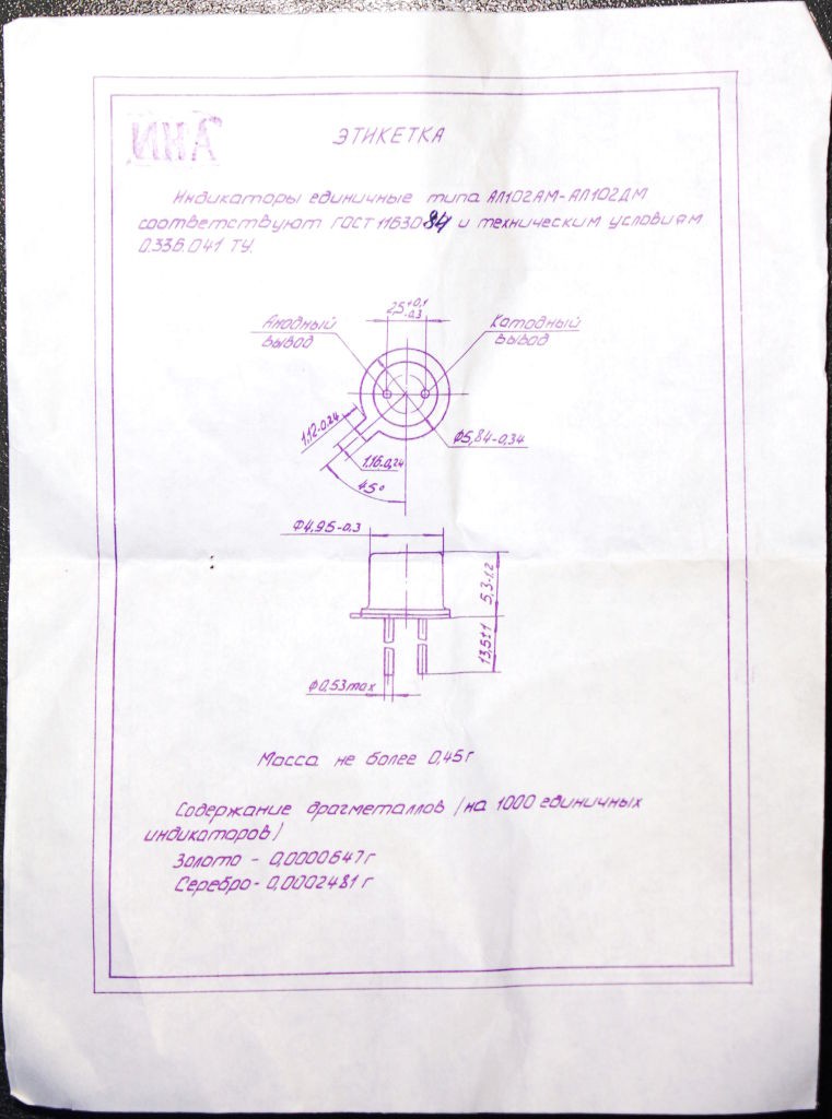
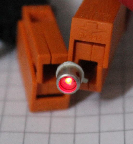
It's not very bright but that was the intention, I was looking at the glow of. the first, low-efficieny LEDs. I'm not sure if it's the BM or БМ version, so I can't be sure it's limited to 10mA, if my guesses are good. Well there isn't much light anyway at 10mA or 20mA and it's intended only as small indicator.
This is the best I could do :
Let's hope it's enough ! If I limit the current to 10mA per LED, the display alone will draw 60mA...
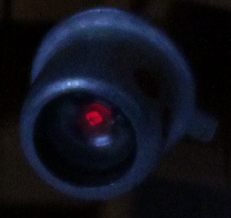
Just for the sake of it, I tried to capture the glow of the LED crystal, at very low voltage (otherwise the camera's sensor is flooded and bleeds) :
Can you see the little square ? :-)
 Yann Guidon / YGDES

Discussions
Become a Hackaday.io Member
Create an account to leave a comment. Already have an account? Log In.
If those OA7's are similar to trhe OC71s I used as a lad, you can modify characteristics by scraping off the black paint on the outside and exposing them to light, esp good for detectors.
Are you sure? yes | no
Yeah I did that. Decades ago I made a flash synchroniser for a friend using one with paint scraped off like you say triggering a SCR to fire a slave xenon flash. Interesting gel-like stuff the semiconductor inside was embedded in.
I gave away my Ge transistors many years ago. Do I miss them? I didn't have enough to make anything substantial and the taker wanted to make amplifiers with retro sound so I think they found a better home.
Are you sure? yes | no
The grey goo is some silicone that helps with heat dissipation.
The OCP71 are without paint or grey, the goo is translucent for optocoupler or photodetection purposes. Power rating is lower because the grey stuff might be some silver-oxide-like heat conductor.
https://hackaday.io/project/58287-bipolar-dudes/log/194574-infrared tries to explain why I bought a handful of OCP71s :-)
Now, it would be interesting to scrape the black paint of the OA7s. But you might have noticed that this log is about 5 years old ;-) I have move this kind of discussions to the #Bipolar dudes group.
Are you sure? yes | no
Ah yes, that reminds me as the OC71s were scrapped transistors from repairs given to me by a telecoms engineer, I discovered that I could make electronic firecrackers out of ones that had no gain by applying a large voltage to it, presumably that heated up the silicone quickly and burst the glass case. Naturally I did this from a distance, having had previous experience with a old car battery, nichrome wire (ex-scrapped toaster), and conventional firecrackers. I was a real-life boy menace.
Are you sure? yes | no
And, very small amendment :)
using base-emitter junction as a diode must be done with great care, as:
1) it is actually zener with somewhat 6 volts breakdown,
2) it has roughly 10 times more reverse current than base-collector junction.
Д311 has 160 mV forward drop under 1 mA, probably the best we can find,
Д310 is same good and allows up 500 mA (at a price of 10 times more capacitance)
When we need high drop Ge, Д18 or Д20 forward drop is 350 mV under 1 mA.
Are you sure? yes | no
Wow ! thanks !
Are you sure? yes | no
Besides. while i value modern LEDs very much for brightness, effectiveness and colors, those АЛ102 are aestetical, as you said. Yes dim, but glowing dice inside silverish can under clear glass window makes style :)
Though old Western devices (Monsanto etc.) are true aestetics too.
Similar visual effect can be seen with modern high power color emitters (Luxeon, etc.), when driving with tiny current. While this is not endorsed by vendors, they can be used as glow dice with current of hundred(s) or even tenths (!) of microamps.
Looking really cool in this role, as their dice is huge!
Are you sure? yes | no
I agree, I've had my share of Luxeons, a decade ago :-D
Are you sure? yes | no
yes, right - a little label :)
so, on the 1st page it is saying that it's single indicators AL102AM-AL102DM under standard GOST 1163084 and technical conditions 0.336.041 TU
then diagram with holes etc
then info about weight - 0.45 gram
then information about gold and silver content (0.0000647 gram and 0.0002481 gram respectively per 1000 indicators)
2n page - main electrical parameters for temperature +25+-10 Celsius degree:
1st column - indicator type
2nd column - luminance (not less than, microg?)
3rd column - constant forward voltage (not more than, V)
4th column - measurement mode - constant forward current (mA)
then some info about labeling (note 1): AL102AM - one red dot, AL102BM - two red dots, AL102VM - one green dot, AL102GM - three red dots, AL102DM - two green dots
then info about color of light (note 2): AL102AM/BM/GM - red light, AL102VM/AL102DM - green light
and then OTK stamp (quality control)
Are you sure? yes | no
OOOhhhh this totally makes sense now ! I didn't understand that they mixed red and green data on the same datasheet... I was curious about why the current rating would fall and rise again :-D
And the gold/silver contents part is totally new for me...
Are you sure? yes | no
added some minor clarifications
Are you sure? yes | no
It's still unclear to me what the "maximum ratings" are, or what the table explains : is it only the testing parameters that were used for binning ? I don't want to exceed the parameters and break one (I have found one that doesn't work already yet have not tested 10 parts yet).
Edit: ah, it's a mix... "no more than 2.8V"
First photons are emitted around 1.7V.
2.8V couldn't be a testing voltage because red LED are usually much lower than that.
I'm still not sure yet about the AM/BM/VM classification, either. AM is tested at lower current and has lower light, so it's not possible to know which class is "better".
Are you sure? yes | no
more dots = better, no?
Are you sure? yes | no
OOOops Alexander is right, it's Д9Б and not Д9B, fixed :-)
Are you sure? yes | no
OOO - ЭТИКЕТКА :)
Russians called that way paper 1-pagers (little datasheets) and it literally means "a label" :)
Are you sure? yes | no
I figured this easily because it sounds like the french "étiquette", just with the diminutive suffix "ka"... little étiquette, how cute :-)
Now I'd like to be sure of the meaning of the other terms, if you could help translate :-)
Are you sure? yes | no