 Yann Guidon / YGDES
-
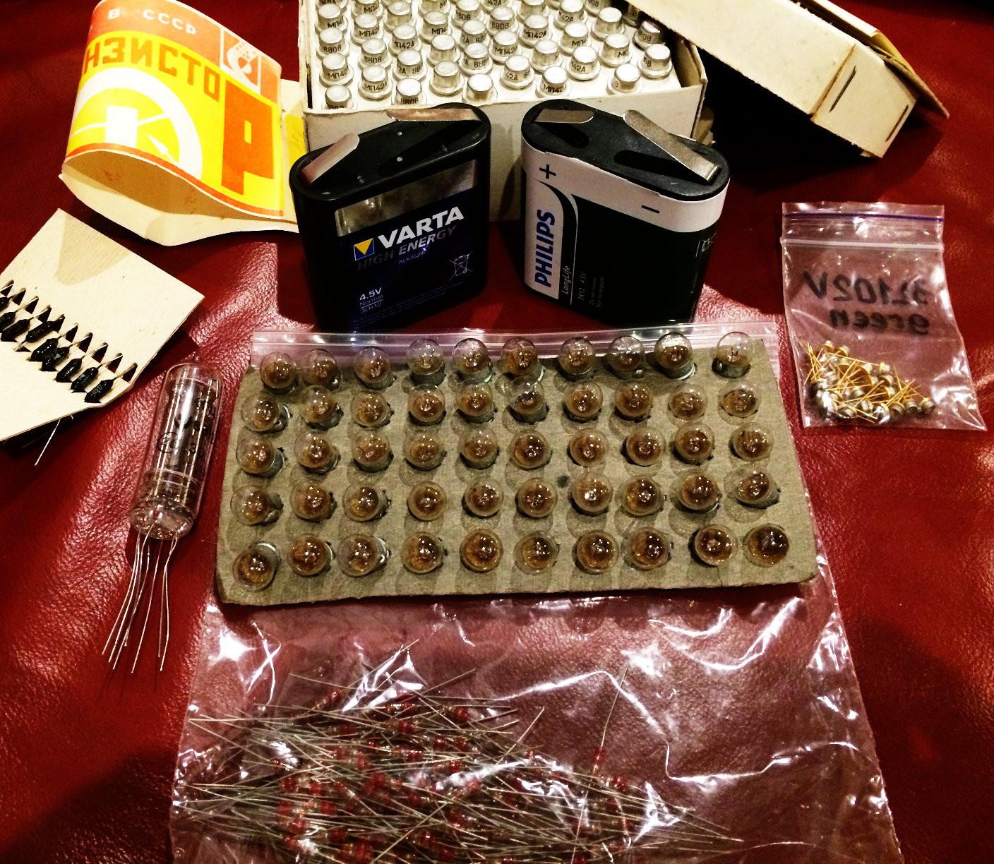
New inventory
05/22/2016 at 19:46 • 0 commentsAs time progresses, I (Yann) am turning more toward European sources of vintage transistors. Honestly, I bought the first Germanium transistors (the soviet МП13Б and МП26А) as "double diodes" for the reset signals and only later I thought about using them for switching purposes.
Still, they look like transistors and the performance is not fabulous. I can get away with many quirks but the efforts must be worth it. I want the parts to be and look special, what's the point otherwise ?
So far I think I have enough transistors to start maybe one or two full-scale assemblies, using:
- AF137 and G106T (Telefunken, PNP, 25V, 60mW, β around 60, 35MHz, to be confirmed) as well as AF200 (another 4-pinner)
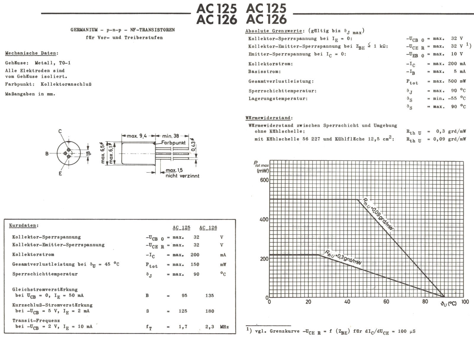
- AC125V (package similar as above, β>90, 30V, but only 1.7MHz)
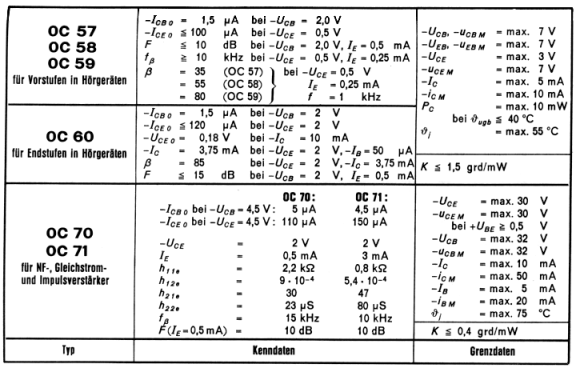
- OC70 (black glass, unmarked)
The Telefunken parts look great to design a "numbers processing circuit". I'm not sure what can be done with only 400pc though.
The AC125 are not fast enough for high speed processing but can manage the clock oscillator and prescaler of the clock. Or more. It's germanium-y and can make a nice clock too. The datasheet is pretty complete (if it's really from the same manufacturer).
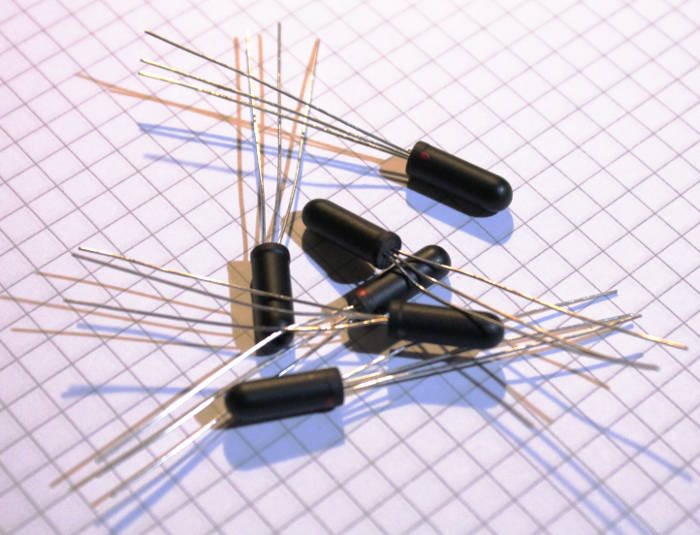
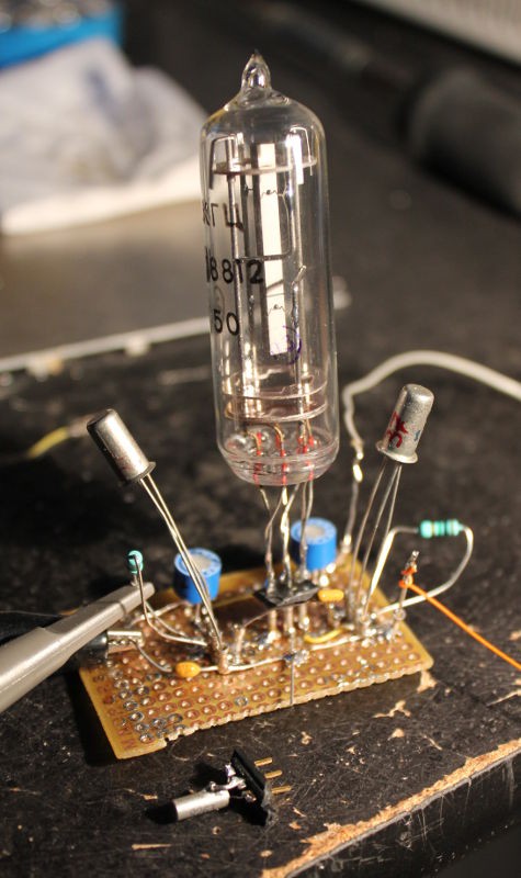
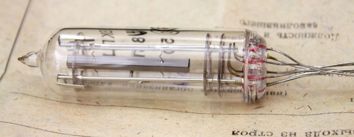
But the OC70 is the thing for this Germanium Clock project, with its totally odd look and antique characteristics, a blast from the late 50s !![]()
![]()
Transition frequency of 15KHz ? Wow that's not fast... So it can only be used for the counter of hundredths of seconds, not closer to the prescaler. I have read somewhere that Mullard's OC70 were used in the first British transistorised computers and digital devices so "it should be ok" and it should suitable for the clock's slow counters.
But the look is just right. If you don't know what it is, you are only left with conjectures:
![]()
And this is one of my goals for this clock project : it's really a clock but you have to think beyond your habits :-) It's always good to relearn old things...
Now that I have the parts, I can start the design of the elementary blocks : latch and counters. There are about 40 blocks but I don't know how many transistors will be needed. I don't even know who manufactured these or when. I'll have to test them !
Update: A pair of randomly picked OC70 of this batch can run the Xtal oscillator at 8KHz !
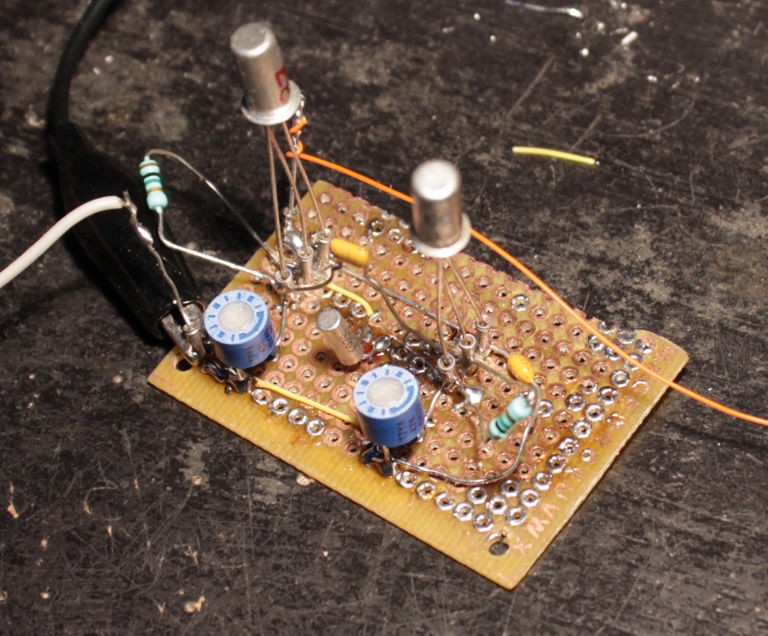
I can better appreciate their characteristics : they are "lazy" with just enough gain but low bandwidth. They can be "boosted" by increasing the power supply voltage though. Oscillation can be sustained at 3V but needs double to startup. The dual-stage amplifier circuit works great and it's important to match the sensor's trimmer to the quartz impedance (the trimmer is set at 16.45K). The other pot is used to center the signal/oscillation in the working range (check with the scope if there is no saturation) and you're done.
What is now missing is:
- Fine frequency tuning (I must have #Hacking a FE-5680B rubidium reference clock working again...)
- sufficiently fast logic for the prescaler (darlington ? non-saturating logic ? higher voltage ? germanium Baker clamp ? sorted gains ?)
BTW, the quartz emits a faint audible whine at 8KHz even when driven with a nice sinewave. Now I understand why 32KHz was chosen, after the first clocks at 8KHz, it was not just a matter of size. Energy gets dissipated through the vibrations and it's proportional to the size. OTOH the very low frequency quartz are large and have a high inertia, which is hard to get moving first, but better stabilises the operation. Conclusion: lowering the amplitude reduces the losses...
-
PCB received
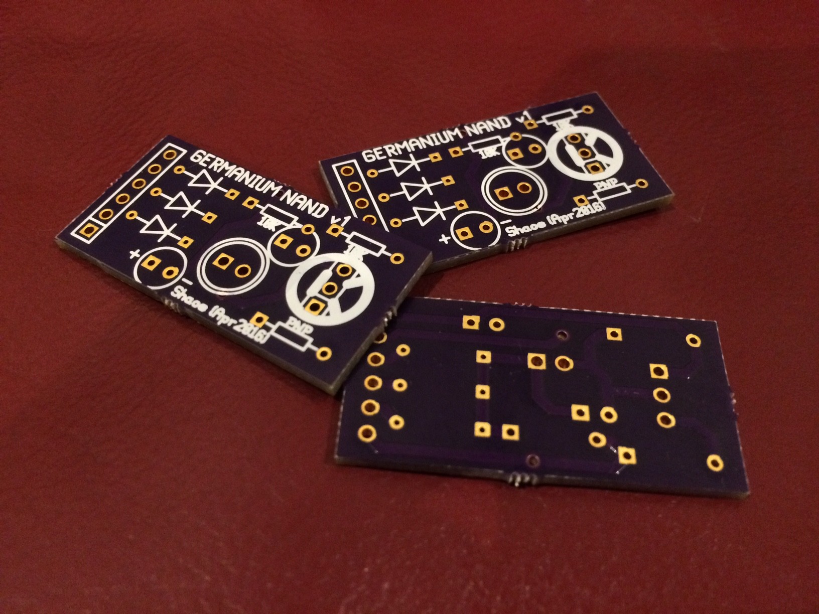
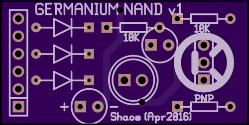
04/19/2016 at 01:20 • 3 commentsI've just received 3 PCB of "Germanium NAND" from oshpark.com
![]()
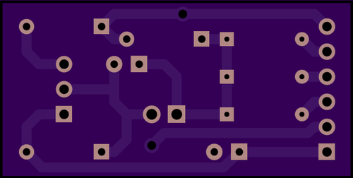
It was drawn in gEDA "pcb" software (images generated by OSHPark service):
![]()
![]()
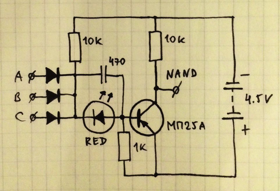
and represents this schematics:
![]()
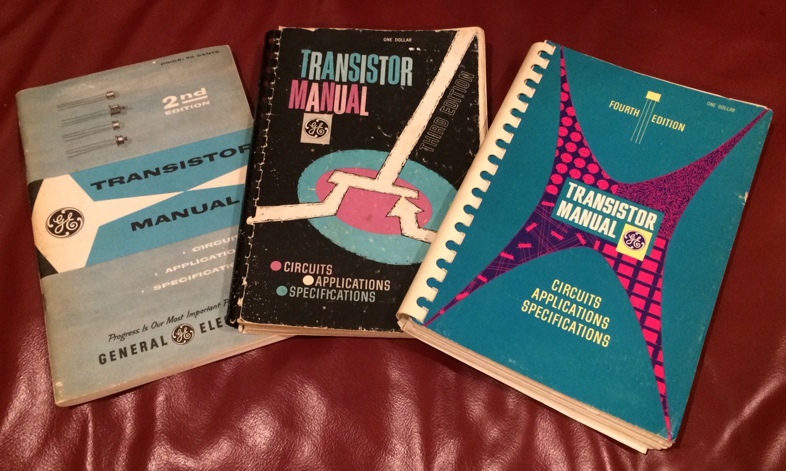
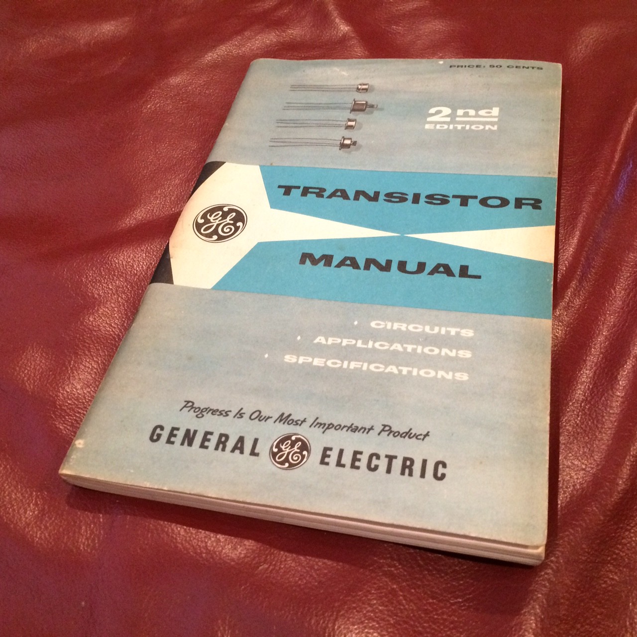
Also I got 3rd (1958) and 4th (1959) editions of "Transistor Manual" from General Electric Company with more schematics of computer components utilizing germanium transistors:
![]()
-
More ingredients to cook germanium
04/17/2016 at 01:22 • 3 commentsMore retro stuff received:
![]()
And in the quartz it looks like only 3 wires are there out of 7 (some of them were connected together or not connected at all):
![]()
It's 2 contacts connected together for 1 side of the crystal and 2 separate contacts on other side of the crystal, so I cut all other wires to keep only 3 important ones...
-
It just works
04/16/2016 at 01:43 • 12 commentsIn the previous episode, Reverse-engineering vintage quartz resonators, we had a lot of questions and a few hints. The best way to be sure was to try them.
I took the previous board (see Crystal Oscillator (Germanium Edition)) and removed the 32768Hz Xtal. Instead I put a 3-pins socket, with ground in the middle. I put the 2 crystals (in succession) on a connector and tested them.
![]()
The wristwatch crystal needs quite specific parameters to work correctly.
The russian crystal just worked, oscillating immediately with the parameter of the tiny crystal. Oscillation persists even with both trimmers cranked up to the max (47K Ohms) at 1.5V (though startup was slow). But even then, it just worked, using low gain transistors (hFE=37).
I feared that operating it would be difficult, like requiring more driving energy because of the larger size (higher motional inertia) and other factors. But the tube just "rings". No I can't hear it but it picked up the oscillations much better than the tiny tuning fork, requiring less energy.
I suppose that the lower frequency also contributes to this sensitivity, since the transistors are not ultra-high performance. So the rough MP13B might work as well. A recent planar transistor will fly. I should still investigate the MOSFETs...
One surprising result was that it works better when the "large electrode" is on the driving side, leaving the small electrode to the sensing side. I haven't tried all the 6 combinations/permutations of the pins yet, though, but this would be a very interesting experminent. But first I need a tool/measure to measure the gain, other than the time taken by the oscillations to reach full range.
Whatever the result, my bet on this tube has been a clear win, on every account. It costs more than a dumb wristwatch crystal but it requires less driving energy so it's energy-saving. It looks much better, might have a better temperature stability and it's pretty unique...
We'll see soon how it behaves and how it is tuned.
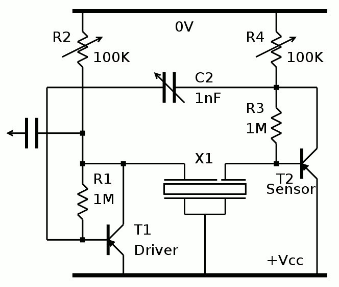
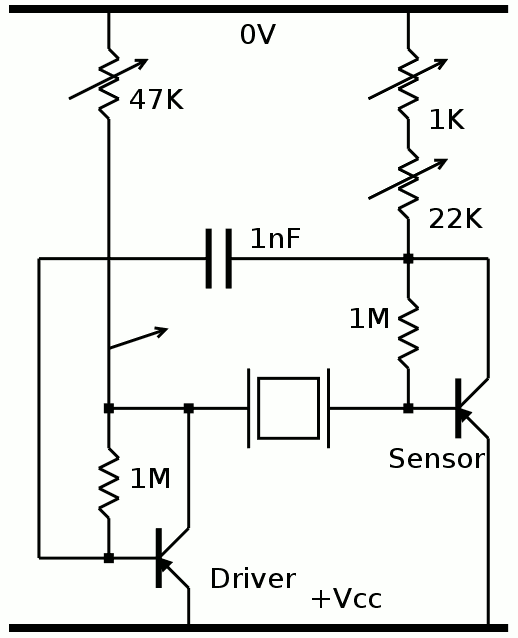
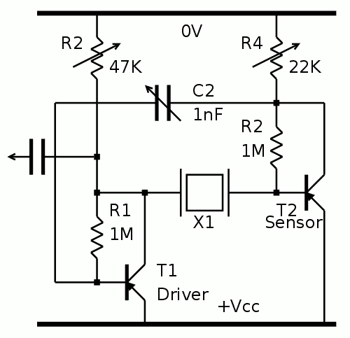
By popular demand, here is the updated schematic :
![]()
R2 and R4 have been increased because the signal saturates fast, and saturation is not good. Actually, the best is to have a small sine, less distorsion and better accuracy.
Due to the higher sensitivity of the crystal, R1 and R3 can be increased as well.
C2 must be evaluated. I don't have the means to calibrate this frequency yet (my #ScoPower gizmo is fixed to 32768Hz). I'm waiting for my Rb source and a DDS.
I will have to evaluate the effect of leakage, thus of temperature-induced drift.
To compensate power supply voltage drift, I'll probably add a micropower voltage regulator. No Zener diode because of the tempco and the worse regulation ratio. This is why I try to make it work at a lower voltage than the rest.
-
Reverse-engineering vintage quartz resonators
04/15/2016 at 16:43 • 0 commentsThe seller provided the following picture but even after receiving the crystals in tubes, many questions remain.
![]()
First, is it series or parallel resonance ?
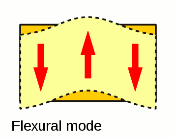
Then what type of cut is it ? https://en.wikipedia.org/wiki/Crystal_oscillator#Crystal_cuts has many choices but many are vague. I can already filter with the frequency range (when provided). The shape of the crystal cut and the plating/electrodes reduce the possibilities further : the oscillation mode is obviously "bending", like a vibraphone bar. From https://upload.wikimedia.org/wikipedia/commons/8/8b/Crystal_modes_multilingual.svg:
The 4 connections are at the "immobile" points of the crystal, to prevent damping, at 1/4 and 3/4 of the length of the crystal (though it looks like 1/6 and 5/6 to me in my tube).![]()
The possible cuts are
- X
- H
- XY (though this fabulous article would not agree)
- NT
The electrodes prevent most harmonic/overtone vibration modes because the "middle" electrode (2/3) short-circuits opposite charges. So the frequency and waveform/shape would be quite pure and stable.
The "passport" that @[skaarj] translated (in the comments) mentions -80°C to +80°C operating conditions, which are another hint for the cut. It seems to be symmetric around 0°C, which is unusual. Finding (or measuring???) the temperature response curve would help even more. Does anyone have a climate testing chamber ?
Initially I feared that the frequency stability would be poor but it might be the reverse, this will have to be measured and I suppose that the germanium leakage will be the greatest source of variations. I'll probably have to find/imagine a balanced/symmetrical oscillator circuit using matched pairs...
One more hint would be the internal connexions. Some electrodes are connected to structural elements, hence have higher capacitance. Some output wires are connected in parallel with the structure, as well.
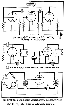
http://www.ieee-uffc.org/main/history-marrison.asp contains a very interesting hint at fig.8 :
![]()
(Wait: what is this "bridge-stabilised oscillator" ? I have to look that up
The two bottom circuits use the classical 2-electrodes quartz but the top one has 4 electrodes, more like my tube !
Update: ok, no, it works in series resistance resonance but I don't know if the tubes are rated for series or parallel mode)I suppose this 4-electrodes crystal works in a different cut/mode but from there, my latest guesses are confirmed and I suppose the following:
- short electrode (1/3) for driving the crystal (with enough drive, but smaller surface if compensated by high gain circuits)
- long electrode (2/3) for collecting the charges and providing feedback
- opposite side electrode (full length, 3/3) is grounded (otherwise, relative to what point do we measure the charges ?)
Or maybe swap 2/3 and 3/3. I'll have to test that... After all there are only 6 combinations :-D
Measurements:
- The quartz bar is 30mm long
- contacts are at 7.5mm from each end
- The short electrode is 8.3mm long
Things add up nicely :-) 7.5×4=30mm, so the oscillation is in bending mode, perpendicular to the electrode platings. Contacts are placed at the point of least motion, to prevent attenuation, at 1/4 and 3/4.
The puzzling part is the 8.3mm of the short electrode, I don't know why this length. The ±3.6 ratio does not correspond to an obvious mathematical relation. It's close to 3.3 and has misled me but maybe the measurement is not precise enough.
-
Got Quartz !
04/15/2016 at 03:41 • 9 comments(See more details in the next log)
So I received the central piece of the quartz clock : the quartz !
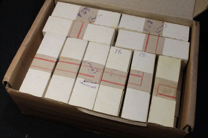
A box arrived from Ukraine, the seller described the contents like this:
"Russian/USSR made Quartz Crystal Resonators 18 KHz. Crystals are in mint condition never soldered. Each crystal is in individual manufacturer's packing box with individual OTK certificate. Manufactured in 1989 Purchased from a storage of electronics manufacturer which is no more in business. "
Why choose these ? Well, there is no need of a socket (which would cost more than the tubes), the price is good (but increasing), 18KHz is not hard to work with (I found interesting dividers) and the look is awesome. A higher frequency means a smaller crystal, which would be less visually interesting and requires more flip-flops to divide down to 1Hz.
The plan is to
- divide by 8 (3 chained toggle cells)
- divide by 15 (4-bits toggle ripple counter, with AND4 to detect number 15 (all 1s))
- divide by 15 again
- Divide by 10 with a Johnson counter (with fancy LEDs to show the 10s of seconds)
Total : 11 toggle (divide by 2) and 5 DFF (16 modules)
23 more FF are needed for the remaining stages, seconds, minutes and hours (5+3+5+3+5+2) [does anybody need a day-of-week indicator ?]
Total: 39 FF modules.
I have NO IDEA what that thing was used for. Why is 18KHz used ?
And I have no clue about the driving method because there are 3 active signals and not two, which is the norm I'm used to.
But let's start by opening the box:
![]()
Can it be more Russian ? :-)
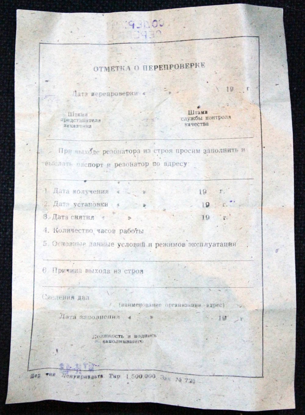
Each little box contains one glass tube and a "passport", a small sheet that describes the part:
![]()
![]()
I'm sure that this last picture contains very interesting informations, about operating temperature and accuracy... But I can't make sense of them yet. Anyway, the date code is obviously 29 dec. 1988 (though Russia uses the Julian calendar, shifted by 13 days compared to the gregorian calendar we use in Europe, so yes, that's 1989 for "us").
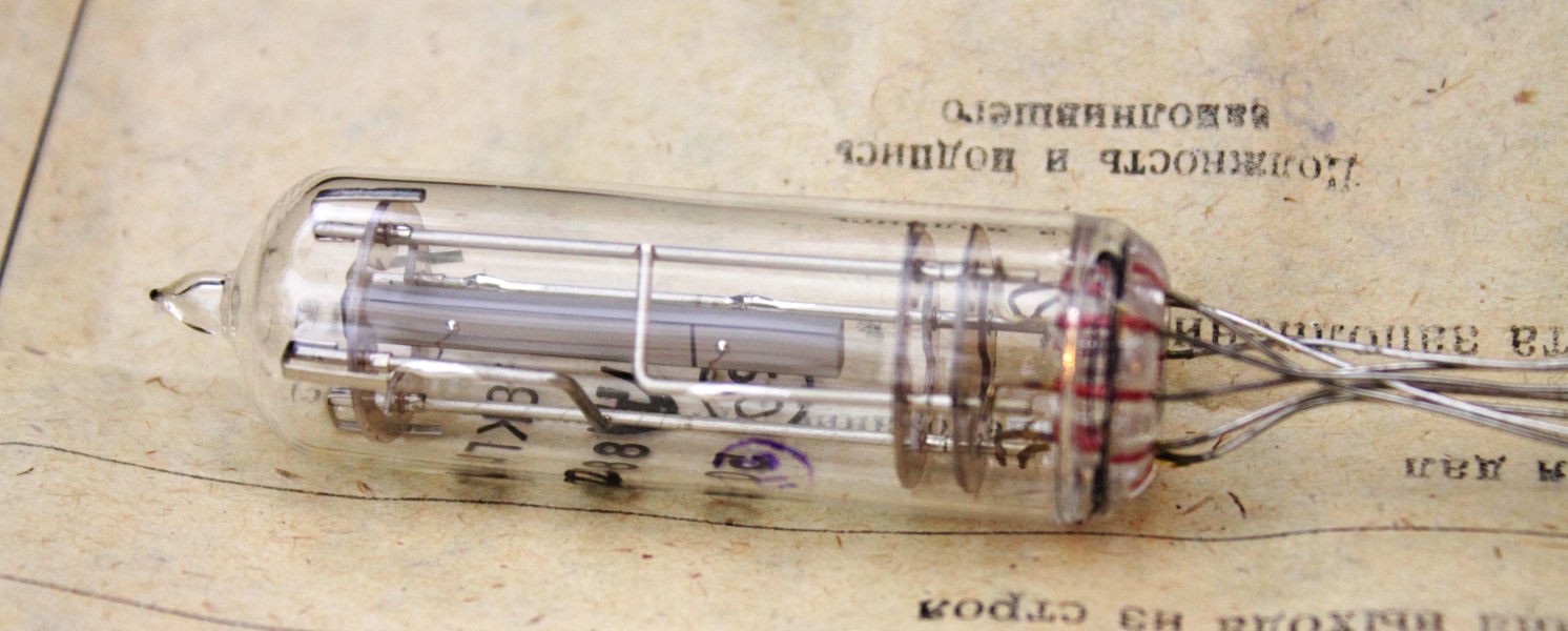
The tubes themselves are great, though I have many questions about their design and use...
![]()
(click to enlarge)
There are 3 electrodes, one at the back (next picture), two at the front, and one is 1/3 of the length only.
![]()
The above picture shows that 2 electrodes support the crystal at the exact opposite of the others. The distances are carefully chosen to reduce interference or dampen the oscillations...
I suppose that the crystal resonates in the bending mode, like a vibraphone plate. However I don't know how to drive it, what is the excitation electrode and the sensing electrode.
I suppose that the excitation is applied through the single electrode on one side, and the small electrode on the other, leaving 2/3 of the surface for sensing/collecting the charges. This structure does not correspond to the stamped logo on the passport, which describes a more classic structure with excitation on two opposite sides, and collection between the perpendicular electrodes.
I have noticed that the quartz bar is not square, but slightly rectangular...
That's all I can say for now. Stay tuned ;-)
-
Vintage transistor book
04/11/2016 at 23:04 • 6 commentsJust got this book from ebay:
![]()
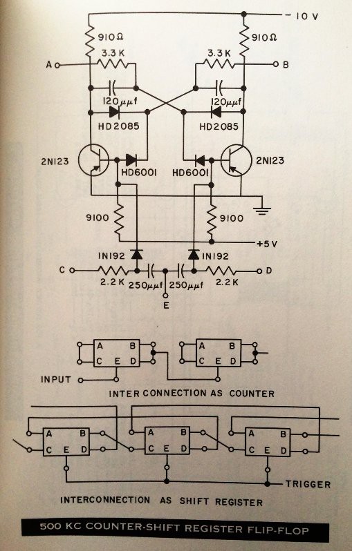
and there (surprise-surprise!) schematics of the trigger on P-N-P germanium transistors that could be used in counters or shift-registers :)
![]()
2N123 is similar to Russian МП42Б (MP42B), 1N192 is similar to Russian Д219А (D219A), HD6001 and HD2085 didn't have direct analog in USSR, but I can try to apply the idea to my current T-trigger circuit...
-
Triggering Germanium
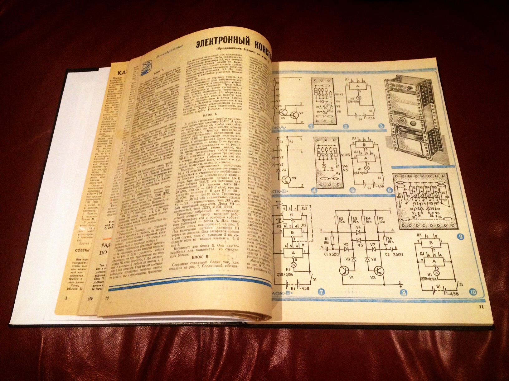
04/10/2016 at 03:11 • 16 commentsSo going further with replicating circuits from old Russian magazine (1983):
![]()
Now using 2 NANDs (version with LEDs) I built trigger (as on Fig.7 above):
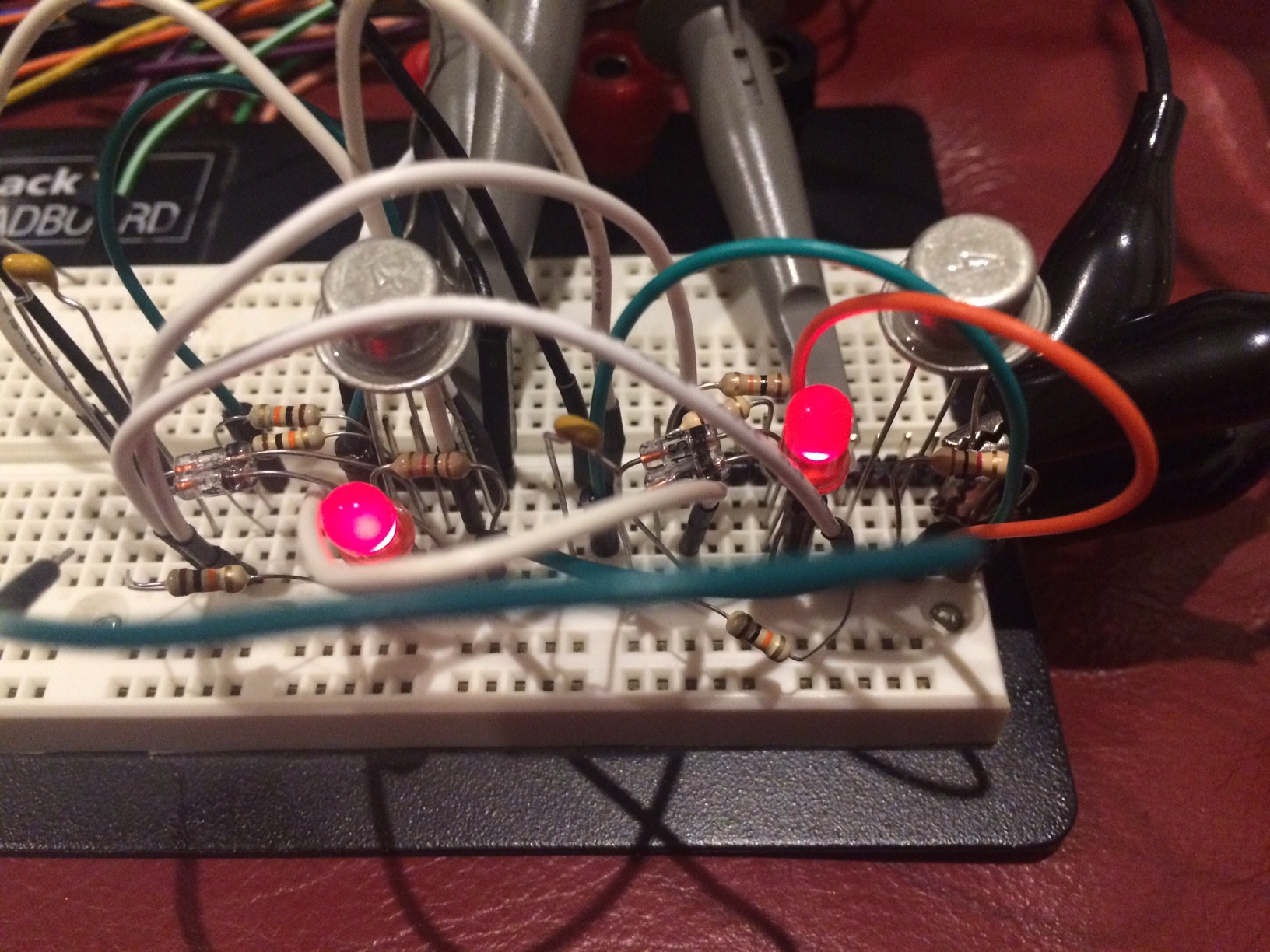
Then added couple resistors and couple capacitors to get universal trigger (as on Fig.8)
![]()
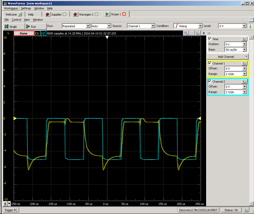
That can toggle state if inputs 5 and 6 connected together - 100 Hz:
![]()
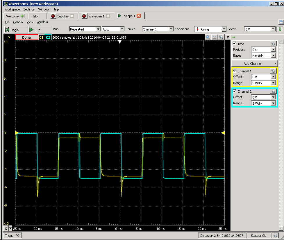
1 kHz:
![]()
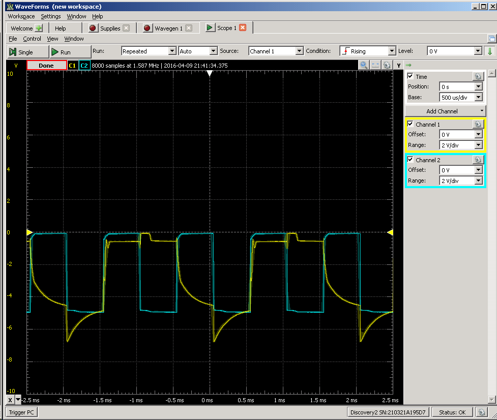
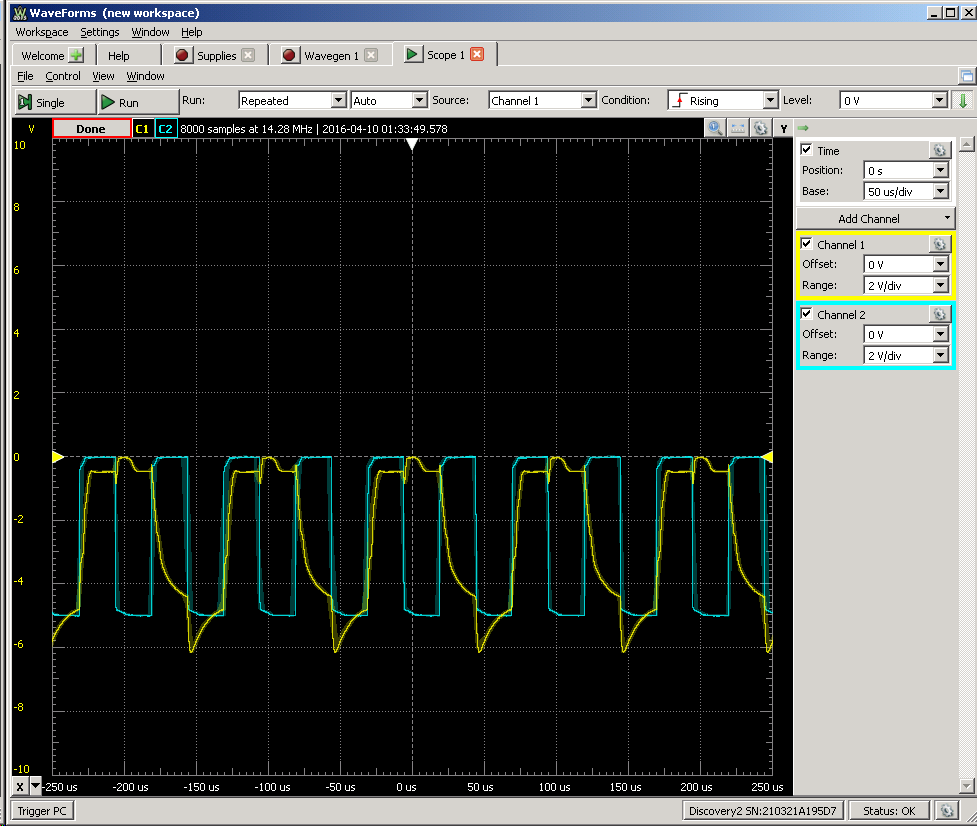
5 kHz:
![]()
It looks like this is a limit (and trick with "speed-up" capacitor doesn't help) - probably I should play with values of resistors and capacitors...
UPDATE: Everything above was for C1=C2=10000 pF, now I'm trying 470 pF
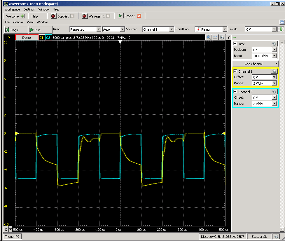
10 kHz:
![]()
20 kHz:
![]()
On 50 kHz it doesn't look good...
UPDATE (04/10/2016): Today 50 kHz looks much healthier - I don't know why :)
![]()
But if go higher output shape is quickly shifted up (to the ground) - probably because of natural limit that caused by latency about 5 us...
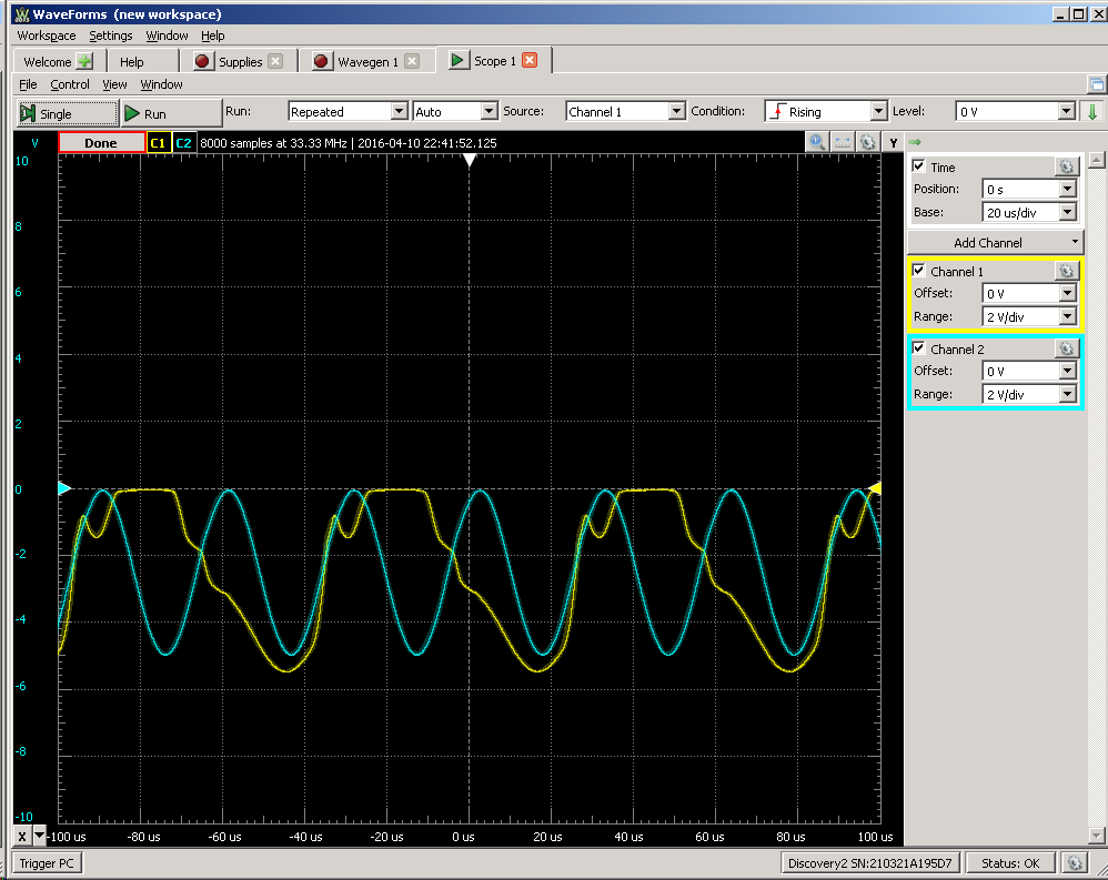
P.S. Almost forgot - 32 kHz sine signal :)
![]()
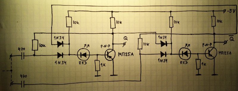
P.P.S. Redrawn schematics:
![]()
Note: Wires that goes above diodes are NOT connected to diodes' cathodes as may mistakenly appear in your mind (check closely - there are no dots there)
-
Crystal Oscillator (Germanium Edition)
04/09/2016 at 04:22 • 9 commentsIn our latest coverage of this thorny subject (Crystal oscillator) our anti-hero met many difficulties that left him hopeless, after a dozen of failed attempts.
SHAOS tipped him about several circuits, such as these ones:
![]()
But this one (found there) seemed the most interesting:
![]()
It evokes the one that was already successful but upon closer inspection, it's actually a 2-stages, capacitively-coupled, high gain amplifier. It is straight-forward to reverse for PNP so I did it. From the past experiences, I replaced R2 and R4 by 47K trimmers, while R1/R3 are dumb biasing resistors, anything goes. C2 is kept at 1nF. (note: see the comments, where Alexander mentions that this value is also influential)
![]()
I equiped it first with a pair of GC117c (see the bottom of Testing Germanium transistors (2nd part)) because they have higher gain and lower leakage. I set the trimmers to 10K each and powered on.
The crystal oscillated immediately !
I played with all the parameters (suply voltages, trimmers, transistor types...)
- The type of transistor matters. Like, a lot. A 2N2907 (gain: 225) works great, the GC117 is good and even the lowest gains (a pair of 36) works nicely. However the 2N396 of my collection, or the MP13A with a gain of 40, or a MP26 work like wet fireworks. I could use a MP13A as at the "sensor" side but it would accept to work with a higher voltage, a GC117c for driving, and different trimmer settings.
- The supply voltage also plays an important role. For this clock I target Vmin=4V, and if possible less because I'll try to regulate the voltage and drop is expected. The GC117 and 2N2907 work down to 2V, though the resistors must be tuned a bit.
- The 2 trimmers are really important.
- R2 is the "gain" of the amplifier, controlling the amplitude and bias. When it's correctly set, the output is a clean sine that has maximal amplitude. The value varies with the transistor and power supply voltage... Max value: 47K
- R4 tunes the impedance and certainly the quartz frequency. I could increase the sinewave's amplitude when R4 is set to a very precise position, so the crystal resontates at its rated frequency. Max value: 22K, probably in series with a 1K trimmer too. Also changes with the transistor type, so this is a required feature, a standard value will not be enough.
EDIT: further experiments proved me wrong, as Alexander suggested in the comments. Forget about the 1K trimmer. Say welcome to a variable C2...
I have a better confidence that it can drive larger crystals, with different ratings and larger energy requirements. The output should be obtained on the collector of VT1 and I will add some weak capacitive coupling to a buffer transistor.
![]()
Compared to the previous working circuit, which was totally symmetrical, this one separates the sensing and the amplification, which provides a better flexibility for tuning. There is one more part (capacitor) but this topology also oscillates with more amplitude, up to the full GND-Vcc range. This amplitude can be reduced by increasing R2, which saves some power. The driving signal voltage doesn't need to be full-range anyway, and this is used as output too, which only needs to trigger the Vbe of a cascaded PNP (Vbe=0.2V) thus only 0.5V amplitude is necessary. The higher amplitude is suitable for the CMOS version as well. It's good to be able to tune one parameter without affecting the other too much.
The type of the transistors is important and the "dumb" MP types (rated around 1MHz) are not suitable. Higher-frequency-capable transistors are needed.
I also understand why some people are so in love with the "germanium sound" : some of these parts are just "lazy" and are rather bandwidth-limited. But here, this does not work.
And now, I can sleep happily with the feeling that I have acquired more wisdom, and I've found a reliable solution for one module of the clock.
Edit: thanks for the comments, guys ! You really help me to make sense of all of this :-)
Updated schematic :
![]()
-
Testing Germanium transistors (2nd part)
04/08/2016 at 22:05 • 2 commentsBefore I can proceed with the debouncing circuit, I have to evaluate the characteristics of the transistors and choose the lousiest (debouncing is not a critical circuit). Fortunately I had built a board for manually Testing Germanium transistors.
Remark: the gain and leakage are tested at 10V but this clock works betwwen 4 and 5V. I had expected leakage to be exponential but it appears to be logarithmic vs voltage... so the values will not change much in practice. The leakage moves (drops during the measurement) quickly too, and it very sensitive to temperature, which is disconcerting. I suppose that the large variations are due to the varying time to manipulate them with warm fingers, varying times to measure, etc.
Oh and gain seems to decrease with temperature... spooky...
I have no experience yet to deal with leakage so I don't know how to proof my circuits against it (and low gain). I would expect a minimum gain of 20 so I can have some margin with a 1:10 resistor ratio for the feedback.
Additionally, leakage seems to be a major obstacle to low power consumption and I hope to get some skills with this design.
Let's now pick 10 MP13 and 10 MP26 at random and test them:
МП13Б (MP13B) :
Off (mV) On (mV) Leakage (µA) Gain 108, 83 516, 470 43, 33 40.8, 38.7 310, 260, 220, 200 770, 705, 640, 623 125, 105, 88, 81 46, 44.5, 42, 42,3 220, 200, 180, 160 640, 608, 580, 543 88, 81, 73, 64 42, 40.8, 40, 38.3 330, 280, 200 740, 680, 580 133, 113, 81 41, 40, 38 230, 200, 180, 160, 100 555, 517, 490, 460, 372 93, 81, 73, 64, 40 32.5, 31.7, 310, 30, 27.2 250, 210, 180 750, 690, 650 101, 85, 73 50, 48, 47 250, 100, 85, 66
(i've left it cool a while)660, 392, 372, 339 101, 40, 34, 26 41, 29.2, 28.7, 27.3 350, 280, 220 790, 700, 620 141, 113, 88 44, 42, 40 220, 200, 160 645, 613, 560 88, 81, 64 42.5, 41.3, 40 230, 200, 180, 130 615, 575, 515, 472 93, 81, 73 38.5, 37.5, 33.5, 34.2 МП26А (MP26A):
Off (mV) On (mV) Leakage (µA) Gain 350, 300, 270 560, 500, 470 141, 121, 109 21, 20, 20 600, 500, 400 880, 780, 660 243, 202, 161 28, 28, 26 230, 210 407, 385 93, 85 17.7, 17.5 360, 320, 250 590, 550, 470 145, 129, 101 23, 23, 22 210, 190 450, 427 85, 77 24, 23.7 240, 210 465, 428 97, 85 22.5, 21.8 300, 250, 200 500, 420, 363 121, 101, 81 20, 17, 16.3 220, 200, 190 413, 390, 378 88, 81, 77 19.3, 19, 18.8 430, 400, 300, 250 630, 600, 480, 430 173, 161, 121, 101 20, 20, 18, 18 470, 400, 300 725, 646, 531 190, 161, 121 25.5, 24.6, 23.1 As you can see, I don't use spreadsheets. I am THAT oldschool. Though I might try to import that in gnuplot, who knows.
Now the most interesting part : МП26А's gain is about 20 and МП13Б is about 40. From the reference number I would have expected the reverse... Once again, it was important to measure !
Alexander confirmed: "without suffix it's 12, with suffix 20...60"
So I wanted to pick the "lousiest" and the МП26А (about 75pc) is selected for the debouncer.
At "room temperature", the leakage is not excessive but 100µA is still much more than what's needed to run a quartz oscillator or other things we take for granted in the CMOS era...
Question : is gain correlated with leakage ? Should I select high or low gain transistors then ? Since the temperature varies widely, it's hard to sort parts by leakage, but I should see if the gain has a positive influence...
SHAOS provided more insight:
- info about some transistors : http://zhurnalko.net/=sam/junyj-tehnik-dlja-umelyh-ruk/1985-10--num5
- MP13 is not here - strange. I found it separately:http://www.eandc.ru/catalog/detail.php?ID=12249
- and this is about MP26:http://www.eandc.ru/catalog/detail.php?ID=12278
for МП26А it's 20...50
for Б it's higher - 30...80
so it looks like without letter it is a trash and higher letter means better gain :)
- page about diodes: http://zhurnalko.net/=sam/junyj-tehnik-dlja-umelyh-ruk/1985-10--num4
(I don't understand russian, BTW :-D)
I also got 10×GC117C. The leakage seems to be lower. 2 parts are dead and the gains are all over the place: 37, 62, 50, 60, 50, 75, 36, 60. Now I understand why "matched pairs of Germanium transistors" was such a thing.
They seem to be a better fit for a Xtal oscillator but I still wonder if the gain is high enough...
For the record:
GC117c low noise PNP RFT
Ge PNP 20V 50mA 70mW F < 10dB
According to http://www.radiomuseum.org/tubes/tube_gc117.html:
Introduced in 1963, made by RFT/HFO/VEB (germany), similar to OC817 (300KHz max)
Clockwork germanium
A retro version of Yet Another (Discrete) Clock, with vintage parts


