Yann Guidon / YGDES
-
2nd approach
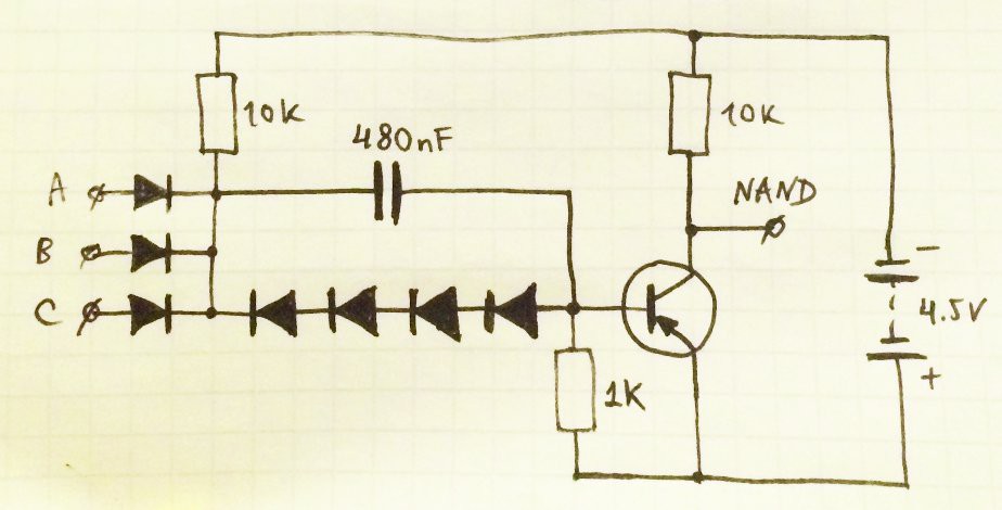
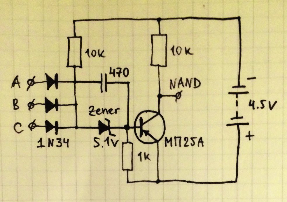
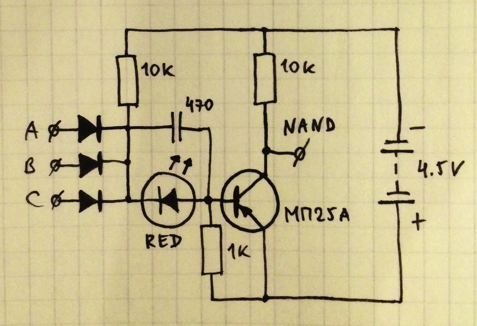
04/07/2016 at 06:46 • 1 commentToday I received some germanium diodes from ebay (1S34 that is the same as 1N34) and decided to replicate circuit from that Russian magazine again - germanium diodes on the left (inputs) and single silicon diode connects transistor base to the inputs common point. And it worked ;)
But voltage transmission curve was not perfect - threshold is too skewed:
![]()
Last time I shifted threshold by adding more diodes in transistor base circuit, but now I try something different - reversely connected Zener diode ;)
![]()
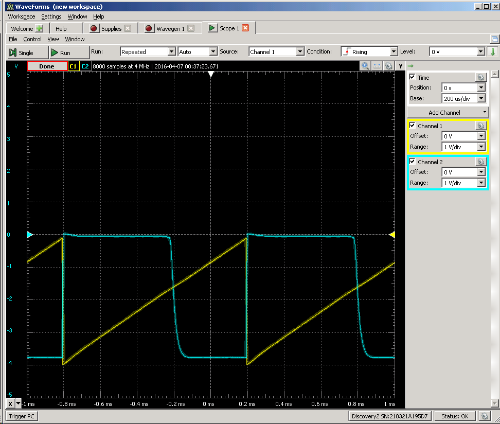
Initially I connected 3V Zener, but threshold goes not too far with it:
![]()
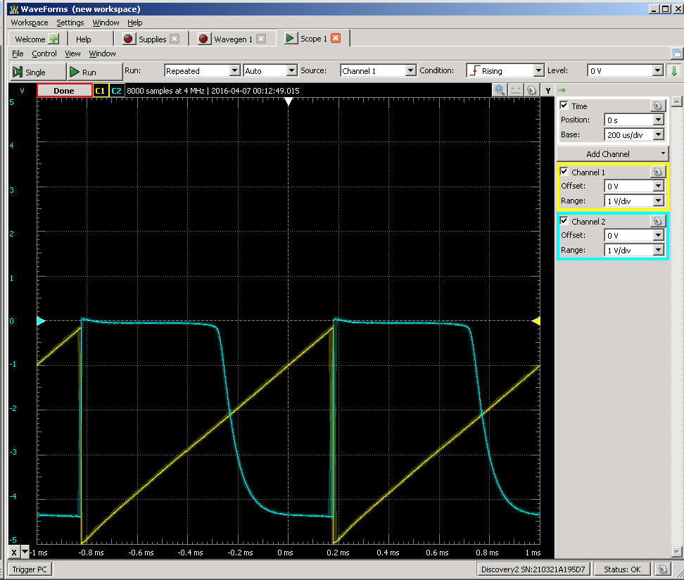
Then I tried 5.1V Zener:
![]()
Much better :)
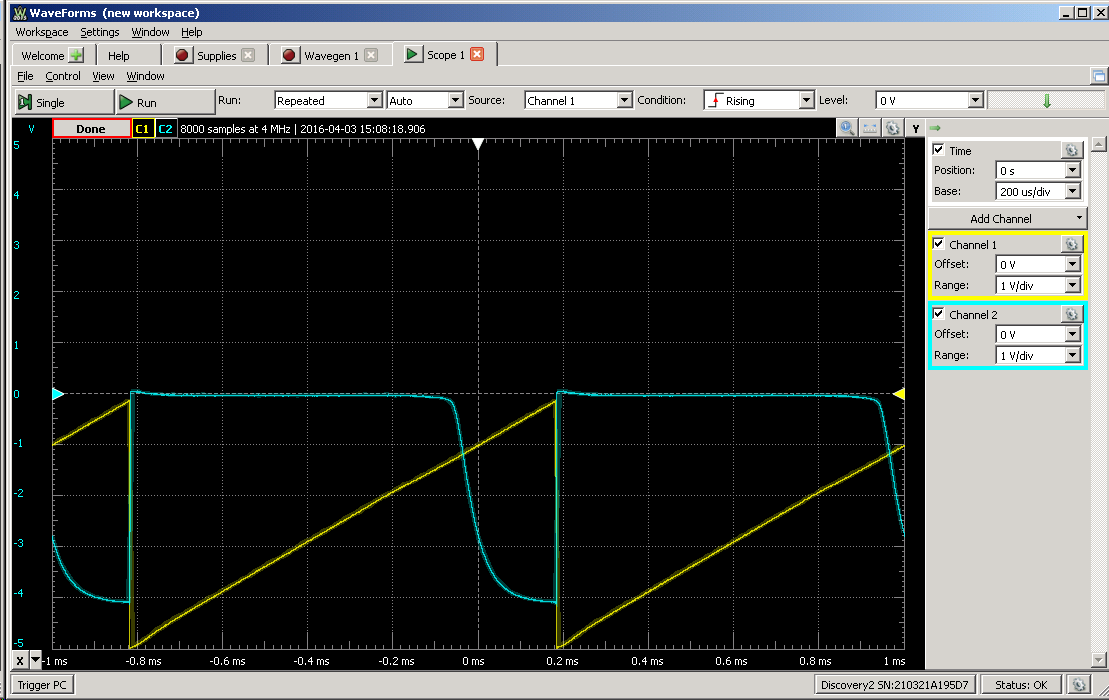
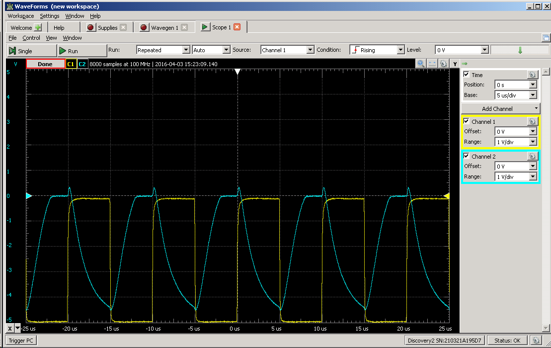
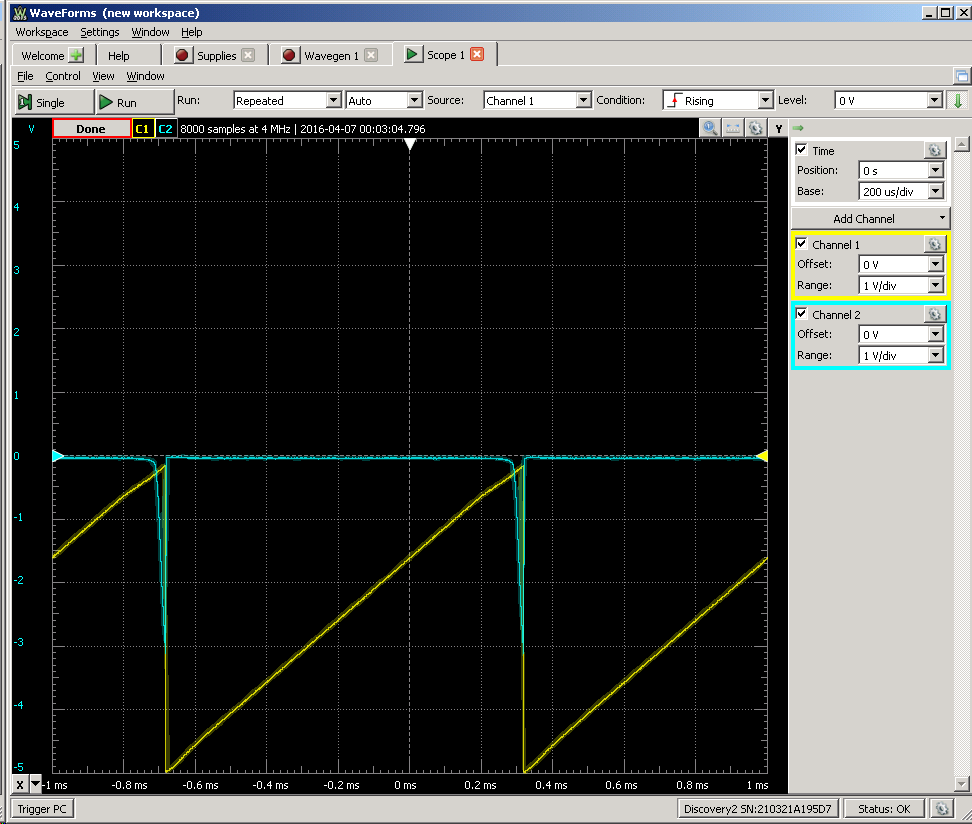
With 4V power this circuit again reached 200 kHz:
![]()
Then I tried even more unusual thing - red LED :)
![]()
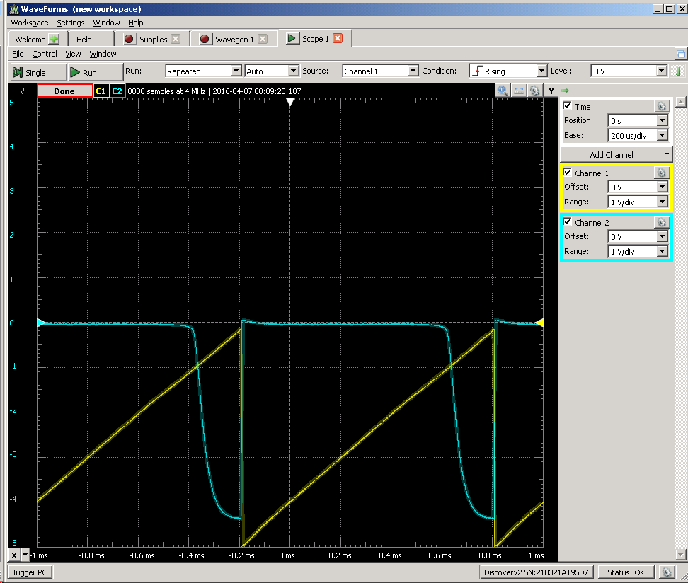
And it worked! U-curve looks like this now:
![]()
LED emits light in "zero" state (indicating AND function ; )
![]()
So we got NAND germanium gate with indicator showing AND function :)
-
Germanium diodes
04/07/2016 at 01:50 • 16 commentsIn the pursuit of authenticity, germanium diodes are being ordered, examined and used.
I already have some 1N60 from a Chinese eBay seller, just in cases I needed to do some fine signal detection (and to change from the Schottky)
![]()
Their forward drop tensions (in mV): 284, 281, 283, 281, 279, 280, 278, 282, 279, 280, 281.... pretty good.
What about the reverse leakage ? Voltages are measured across a 10K Ohm resistor when 9.82V is applied to the diode and resistor : 100µV/10K=10nA (my DMM can't resolve more and the readings decrease quickly)
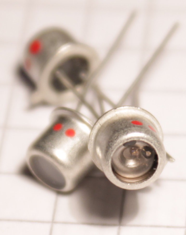
But the "look" of the 1N60 makes it too close to a vulgar 1N4148... Why make a special circuit if it doesn't look special ? So I got myself a little lot of Д9Б (pronounce D9B because it's russian) and their larger glass package lets you see the spring-y point-contact structure. Awesome :-)
![]()
![]()
I measured the following forward drop voltages (in mV) : 278 286 271 288 255 264... It's less consistent, more scattered, I should expect from 0.2 to 0.3V of drop (this depends of course on the current).
![]()
What about the reverse leakage ? Across the 10K resistor I read (in mV): 23, 30, 28, 53, 34, 50, 29, 24, 36, 34... So I have to expect up to 0.5µA of leakage (at 9V). That's 2 orders of magnitude leakier than the 1N60 but still way less than a Germanium transistor...
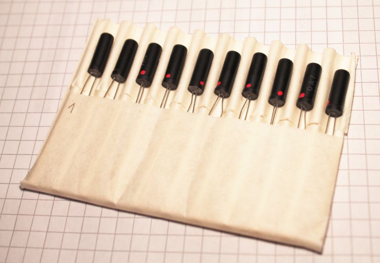
But wait, the pursuit does not stop there. On the Internet, there is a smal (monetary) line between funky and spooky. I got some crazy looking OA7 diodes and the untrained eye wouldn't know what this 2-legged thing is. "Is this an antique capacitor ?" Awesome ;-)
![]()
I got 10pc OA7 (yet). Don't they look cute ? Like they are sleeping in a very wide bed...
I measured the whole lot's characteristics:
n° drop (mV) Leakage (µA) 1 242 1.6 2 245 1.31 3 236 2.09 4 234 1.61 5 237 1.60 6 240 1.63 7 243 1.30 8 238 1.16 9 244 1.34 10 232 2.27 The drop is lower than the others. This is balanced by a higher leakage, up to 5× the D9B. This is yet a, probably, a better detection diode.
I have once found Philips-made diodes with ultra-low forward-drop voltage for analog detection purposes but they are too modern ;-)
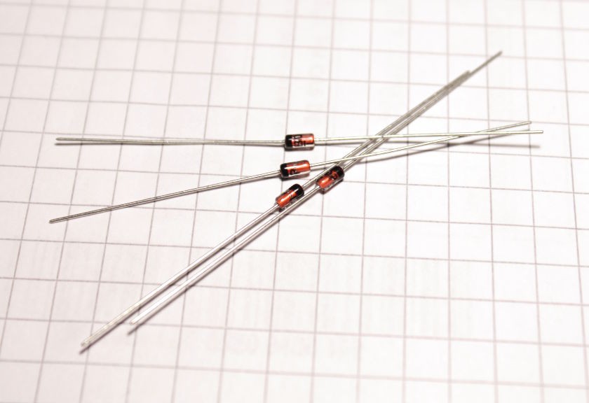
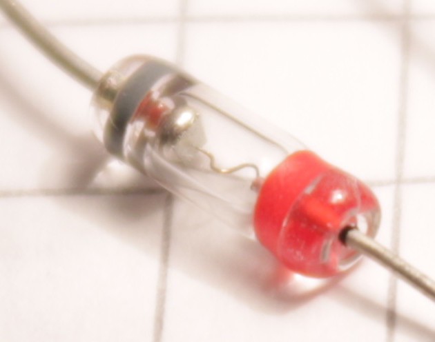
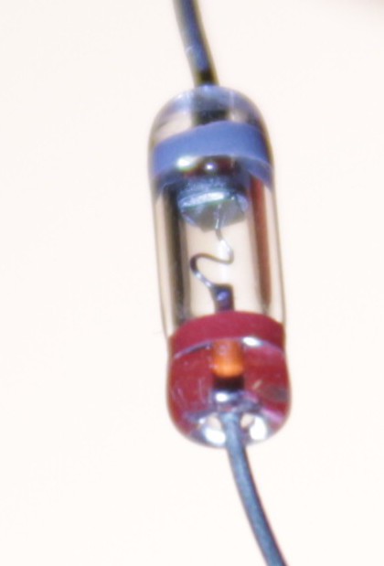
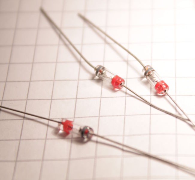
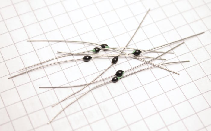
I also found in my archive 40 tiny bead-like diodes. They are pretty and quite unique so they might be used as well, despite being Silicon-based ;-)
![]()
More diodes should arrive (D311, more OA7, maybe OA9) and they will be tested as well but there is something else I have to do !
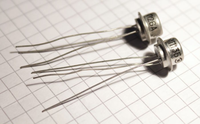
I had bought the first Ge transistors lots because I want(ed) to use them as double diodes... There would be less wiring to do when I want to reset 2 flip-flops with the same signal. So let's see if this works.
![]()
I got some МП13Б (MP13B) :
n° Vf1 (mV) Vf2 (mV) 1 186 196 2 202 189 3 194 201 4 206 196 5 203 192 6 203 191 7 202 190 (I didn't care about collector/emitter order but they can be guessed by whichever is higher by 10mV)
and МП26А (MP26A):
n° Vf1 (mV) Vf2 (mV) 1 180 170 2 193 180 3 194 185 4 187 177 5 185 174 6 190 179 7 189 177 The values are pretty consistent and even lower than the above diodes !
Now it has to be seen if the leakage and the transistor effect will wreak havoc in the circuits...
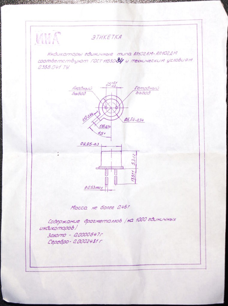
LEDs are diodes, right ? Alexander just used some for his NAND logic gate. Well I got some AL102BM as well, for function AND aesthetic :-)
![]()
The package came with a little datasheet :
![]()
![]()
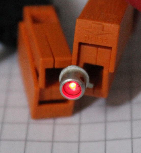
It's not very bright but that was the intention, I was looking at the glow of. the first, low-efficieny LEDs. I'm not sure if it's the BM or БМ version, so I can't be sure it's limited to 10mA, if my guesses are good. Well there isn't much light anyway at 10mA or 20mA and it's intended only as small indicator.
This is the best I could do :
![]()
Let's hope it's enough ! If I limit the current to 10mA per LED, the display alone will draw 60mA...
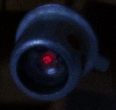
Just for the sake of it, I tried to capture the glow of the LED crystal, at very low voltage (otherwise the camera's sensor is flooded and bleeds) :
![]()
Can you see the little square ? :-)
-
Crystal oscillator
04/06/2016 at 03:33 • 0 commentsMaking a 32768Hz crystal oscillate has been a major concern lately. See Slow oscillations, Oscillators' basics, Crystal oscillator with complementary MOSFETs
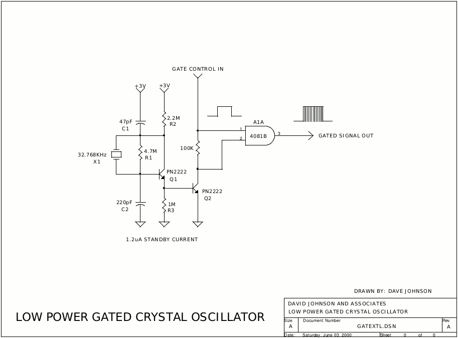
This time I was curious to try http://www.discovercircuits.com/DJ-Circuits/gatextl.htm
That's a pretty mean one.![]()
The great news : it started to oscillate immediately.
The other news : ok I used a pair of 2N2907, PNP, hFE=230 so I inverted everything. No logic gate but I kept Q2 for amplification. I measured 15µA so I'm happy.
However I quickly found that the power supply voltage was crucial in weird ways. The provided values are good for an average system but it didn't work at 3V, only between about 1.5V and 2V for a usable range.
I replaced R1, R2, R3 and the 100K with adjustable resistors and started playing...
Forget R1, keep it very high, it just keeps a tiny current path between the crystal's pins.
R2 and R3 are more tricky. Oh, R3... Remove Q2 and the thing won't work. Yes, its base-equivalent diode biases the emitter of Q1 ! So actually R3 is in parallel with the base and also adjusts the output signal's level.
R2 and the 100K also adjust the offset of the output signal.
I don't know why, but some 50Hz got picked up after a while, or maybe there is some over-oscillation surimposed. Freaky, even if I powered from a battery.
Capacitor values are important too, and the "Pi network" was initially following the schematic, but why 220p ? Well increasing the capacitance seems to be the only good way to increase the signal amplitude. So I replaced the 47p with 220p... Maybe 1nF will increase the amplitude even more ? Anyway there's a big square signal when I touch one pin...
I'm a bit miffed that the thing won't work at 3V as advertised. The final system would work at 4.5V and at least one resistor will have to be adjustable to give the proper amplitude...
Next in line is this circuit : http://www.discovercircuits.com/H-Corner/32hz ultra low power crystal oscillator.htm
Oh and I have to try with Germanium transistors ;-)
Edit : many measurements were wrong. Particularly, it's very sensitive to the mains interference (50Hz here). I must find something else.
-
Testing Germanium transistors
04/05/2016 at 19:48 • 2 commentsSo I had 3 transistors in my archives, one 2N1926 and two 2N396.
My first test with the attempted Xtal oscillator failed. I had tested the 3 with my DMM and found inconsistent results.
@jaromir.sukuba pointed this to me : http://www.geofex.com/article_folders/ffselect.htm
Go and read this page then return here ;-)![]()
I built the device and went to work. I had to measure twice because the values varied all the time :
Type off (mV) on (mV) leakage (µA) gain 2N1926 600, 1000 1370, 1850 242, 404 77, 85 2N396 170, 122 940,857 68, 49 77, 73 2N396 540, 480 1600, 1530 210, 194 106, 105
It's... weird. But also eye-opening !The leakage changes constantly, but the gain is pretty stable with this system.
A pair of transistors have pretty high leakage and appeared as high gain, my DMM measured 150 for two and 100 for one... But the 2N1926 is the least good of the pack.
When I receive the eBay orders, I'll try to sort each transistor to avoid the highest leakages.
20170119:
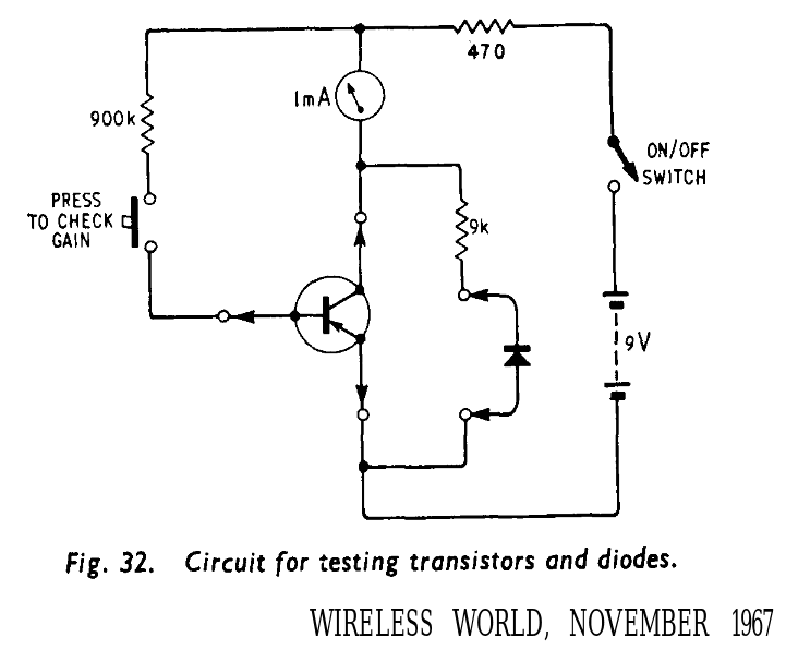
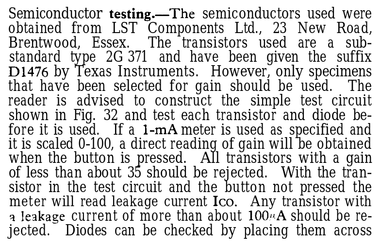
I just found some more germanium testing advices from 1967 at http://www.smrcc.org.uk/members/g4ugm/Manuals/wirelessworldcomputer.pdf
![]()
Damn, even diodes should be tested for leakage....![]()
-
1st approach
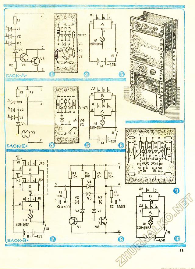
04/04/2016 at 04:08 • 13 commentsYann asked me to describe my experiments with germanium transistor here as a project log. So here it is - when I was a kid my family was subscribed to one Russian magazine for kids that once published series of articles about electronic constructor, build from easy available components and in that time (1983) those components were germanium transistors and diodes, so when I noticed this new "germanium" project I immediately remembered those series - this is article that showed how to build NAND circuit first and then RS-trigger from it:
http://zhurnalko.net/=sam/junyj-tehnik-dlja-umelyh-ruk/1983-03--num10
http://zhurnalko.net/=sam/junyj-tehnik-dlja-umelyh-ruk/1983-03--num11
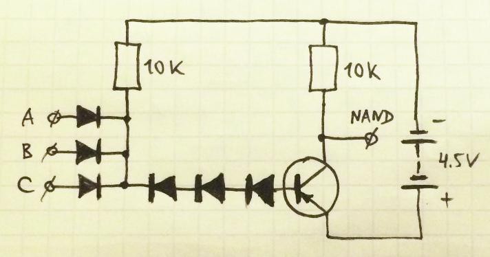
So I took this idea:
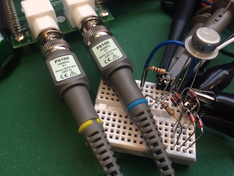
and applied to germanium transistor that I have in hands, Russian P-N-P transistor MP25A manufactured in September 1979:![]()
![]() In the beginning I literally replicated the circuit, but added 3 silicon diodes instead of 1 connected to the base (otherwise it did not run):
In the beginning I literally replicated the circuit, but added 3 silicon diodes instead of 1 connected to the base (otherwise it did not run):![]() UPDATE: Article is saying that diodes on the left must be germanium and diode connected to the base of transistor must be silicon - if we do exactly that then it's working, but if you put silicon on the left then base should be connected to more than 1 diode as on schematics above...
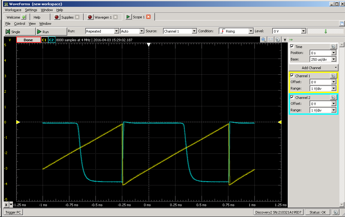
UPDATE: Article is saying that diodes on the left must be germanium and diode connected to the base of transistor must be silicon - if we do exactly that then it's working, but if you put silicon on the left then base should be connected to more than 1 diode as on schematics above...I was able to run this circuit up to 10 kHz:
![]() and just for the record - 5 kHz:
and just for the record - 5 kHz:![]() Voltage transfer curve looked like this:
Voltage transfer curve looked like this:![]() Then I added 4th diode:
Then I added 4th diode:![]() Then I added resistor 1K from base to emitter and "speed-up" capacitor as described here:
Then I added resistor 1K from base to emitter and "speed-up" capacitor as described here:
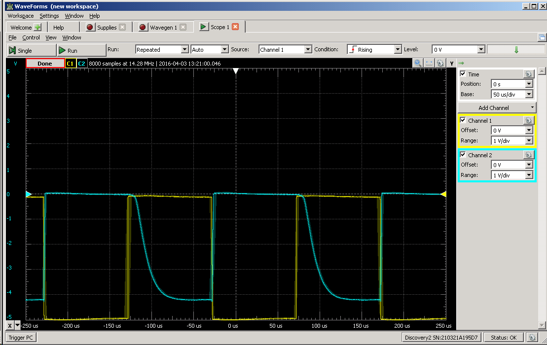
https://hackaday.io/project/6668-aytabtu-discrete-computer/log/23923-more-speeeeedFinal experimental circuit:
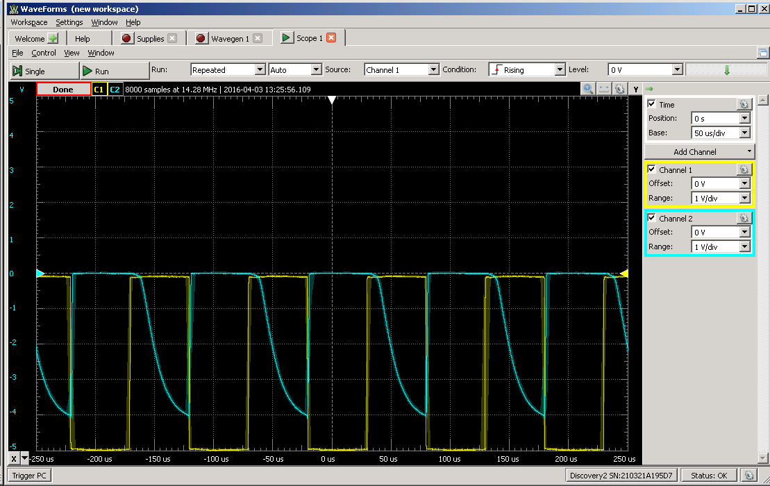
was able to run on 100 kHz!![]()
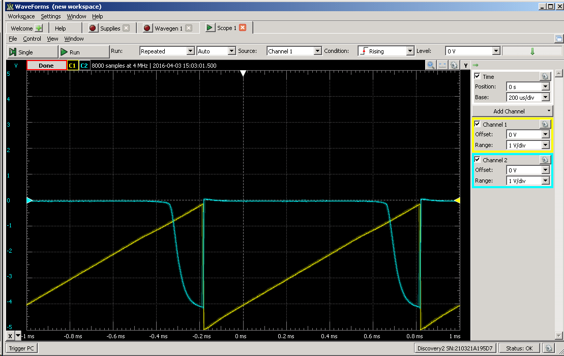
and by reducing voltage to 4V I even got 200 kHz!!!![]()
Now voltage transfer curve looks like this:![]()
P.S. Just ordered germanium diodes to try to be 100% antique ;)![]()
Clockwork germanium
A retro version of Yet Another (Discrete) Clock, with vintage parts


 and just for the record - 5 kHz: