Close
0%
0%

OtterVIS LGL spectrophotometer

A super cheap decently resolving open source VIS-spectrophotometer. The cheapest in the OtterVIS line.

Similar projects worth following
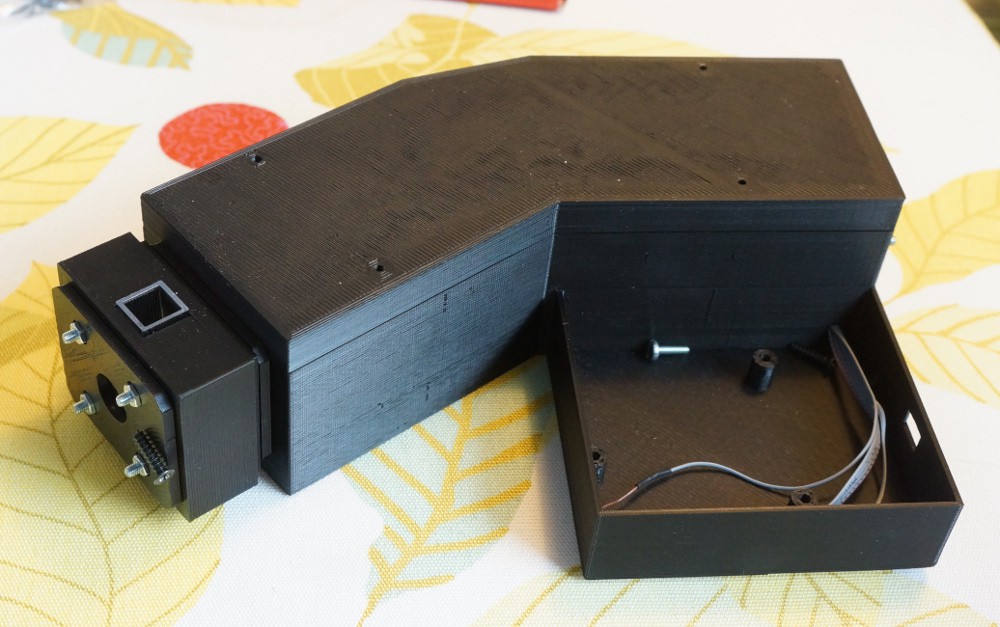
The OtterVIS LGL is a cheap 3D-printed open source lens-grating-lens visible spectrophotometer. What more do you need to know?

It's so cheap it can be literally given away to public schools to help spark their pupils interest in science, or as a high school science project prize. (And I intend to do both). The main goal however is to populate my high school's lab with one spectrophotometer pr 2 students, and to give others the possibility to do the same.

School budgets are tight and even cheap low quality low resolution spectrophotometers easily cost 700$ or more per piece. Acquiring enough equipment to be able to engage all students at the same time can be something of a financial challenge.

I aim to keep the cost for the OtterVIS LGL under 100$.

The optics are chosen for their quality, availability and low price.

The OtterVIS LGL is a super cheap decently resolving entirely 3D-printable open source DIY spectrophotometer.

I've aimed at keeping costs low and quality high.

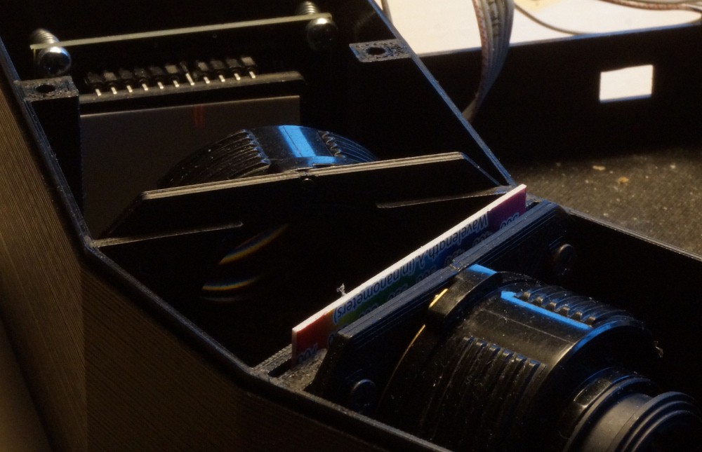
The OtterVIS LGL spectrograph is a lens-grating-lens design.

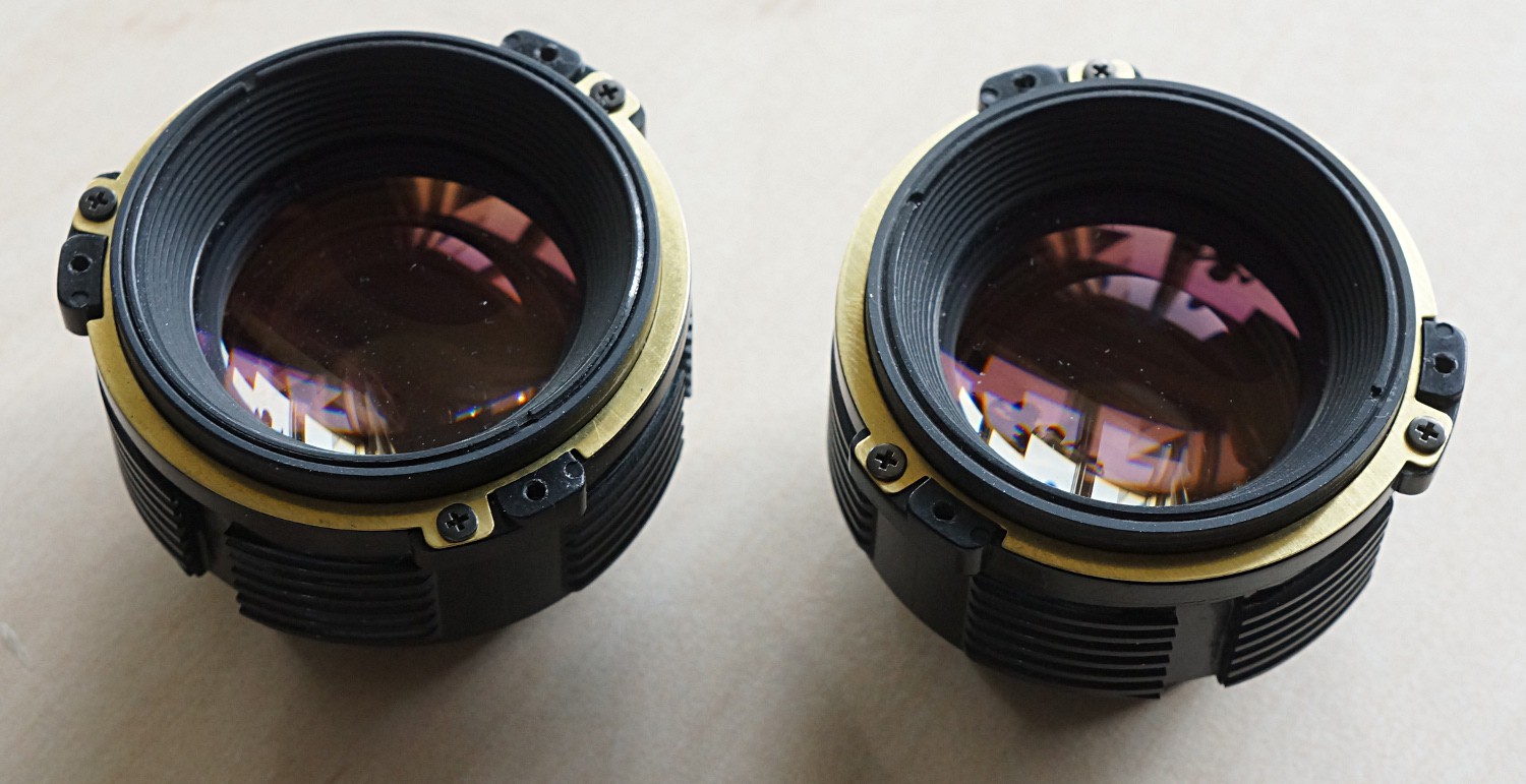
The lenses are two manual 50mm standard camera lenses. Most modern (modern as in post-1970) standard lenses are excellent performers, and because they were "standard" in their time, they are plentiful and cheap today. Cheaper even than simple spherical lenses.

The grating is probably the weak link, as I went with a very cheap diffraction grating slide as opposed to a proper transmission grating. Still I believe it's better than a DVD.

The slit is comprised of to razor blades mounted on a ring magnet stolen from my girlfriends refrigerator magnet collection.

Principles of operation:

The diagram for the spectrograph is as follows:
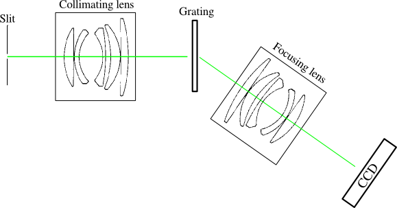
The first lens collimates the light from the slit. The second lens focuses the diffracted light onto the CCD.

The general diffraction equation is:

Which for first order diffraction (m=1) with an angle of incidence of 0° (the grating is normal to the collimating lens) reduces to:

The grating constant is 1000 lp/mm and the lower wavelength is chosen to be 380 nm as the lenses start absorbing here. From 760 nm second order diffraction starts to overlap so 760 nm is chosen as the upper limit for the spectrum.

Inserting these values into the diffraction equation gives angles of diffracted light from 22.3°-49.5°. The center angle is 35.9°.

The CCD (TCD1304) is 29.1 mm long and and with a bit of trigonometry we end up with an ideal focal length of 60mm for the focusing lens. A bit higher than the 50mm actually used, so a part of the CCD remains unused.

License:

Everything comes with the FreeBSD-license, except for the Nucleo F401RE which is under ST's evaluation license.

magnetic-cell-holder.zip

SCAD's for the magnetic spectroscopic-cell holder.

Zip Archive - 1.55 kB - 06/16/2016 at 15:01

Download

OtterVIS-LGL-spectrograph-scad-files.zip

The OtterVIS LGL spectrograph. Edit the poly-definitions file.

Zip Archive - 4.05 kB - 06/16/2016 at 14:59

Download

pentax-front-int.scad

Pentax SMC-A 50mm f/2 lens holder for the OtterVIS LGL

scad - 1.38 kB - 04/05/2016 at 17:06

Download

  • Other lenses

    esben rossel08/31/2017 at 06:06 0 comments

    I've used Pentax SMC-A/M 50mm f/2 lenses for the OtterVIS, but of course others will work as well.

    This week I got my hands on two different 50mm Olympus lenses. Here are some thoughts on them:

    The very easy to find Zuiko 50mm f/1.8 is not really very suitable. Once taken apart, the lens barrel isn't much smaller than the lens in it's entirety.

    The less abundant Olympus PF 50m f/2 is a different story. Once removed from the focusing helicoid, the lens barrel is quite small. And it's almost as if it's made to be taken apart. There are very few screws to remove and the lens groups are held together with holders with bayonetts. One drawback is that there are no screw holes to secure the lens to spectrometer.
        The lens is from the 'power focus line' (hence the PF designation) and the demand for them is small since they are virtually unusable as manual focus lenses, so if you can find them they are likely to be much cheaper than their predecessors. Without knowing for sure, I'd say the optics are identical to the venerable Zuiko 50/1.8.

  • Sodium and mercury

    esben rossel02/07/2017 at 17:59 0 comments

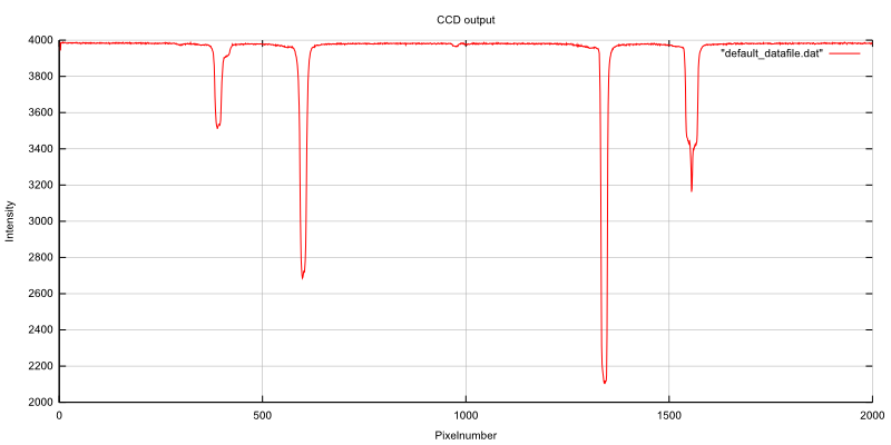
    Hg spectral lamp:

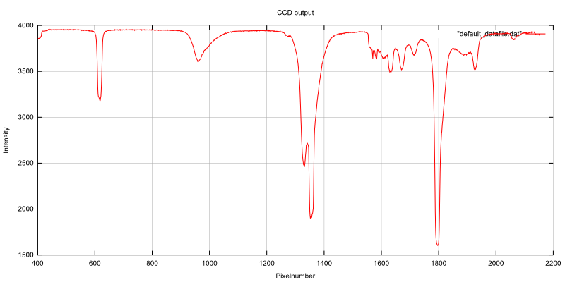
    The line at pixel no. 1340 is mercury's emission at 546.0 nm. At pixel no. 598 is the 435.8 nm line.

    It's not entirely accurate to assume a linear relationship between wavelength and pixel no but let's assume that tan θ is linear for small intervals (and here we're talking about a difference of 6.4° of θ for the diffracted light for the two lines). That gives 0.15 nm / pixel.

    Of course I'm not getting a resolution like that.

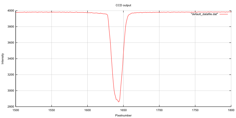
    Here's a capture of a Na spectral lamp:

    It's supposed to be two lines at 589.0 nm and 589.6 nm. If you really want, you can sort of persuade yourself that there's a hint of two lines here. But they are really not resolved.

    Maybe it's the focusing, maybe it's the plastic grating, maybe it's my sticky fingers on the CCD. Whatever it is, it's smearing the picture.

    Let's go back to the CFL-test of the weekend:

    With the "calibration" with the Hg-lamp we can now say that he two lines at around pixel no. 1325 and pixel no. 1352 are 4.0 nm

    apart. (I'm not sure I can afford the .0 in this statement). But it's safe to say that the resolution of the spectrometer is somewhere between 1-4 nm.

  • CFL test

    esben rossel02/05/2017 at 13:54 0 comments

    I've been so busy trying to learn the basics of linux tty, that I forgot to follow up on this project.

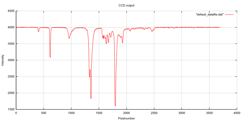
    Someone asked about a CFL-spectrum and here it is:

    I don't have a reference spectrum to compare with, but my 532nm laser pointer gives a peak at around 1250 pixels, so I guess the peaks at 1350 pixels is the 542.4 nm terbium line and 546.5 nm mercury line.

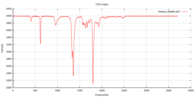
    I took the liberty of zoomin in:

    The "lines" are a bit round, so I guess I could do a better job with the focusing.

    Next week in the universe. Tests with the spectral lamps at work..

  • Recordings of laser lines

    esben rossel07/01/2016 at 08:25 4 comments

    The construction of the spectrometer is close to an end. Yesterday I spent the afternoon doing my best to focus the diffracted light onto the CCD. It's not as easy as collimating the slit - there are no tricks with mirrors that I know of.

    By eye (and with a ruler), I simply tried to estimate the distance from the imaging lens that a 532 nm laser pointer would produce the most well defined line on a piece of paper, and then position the CCD at this position.

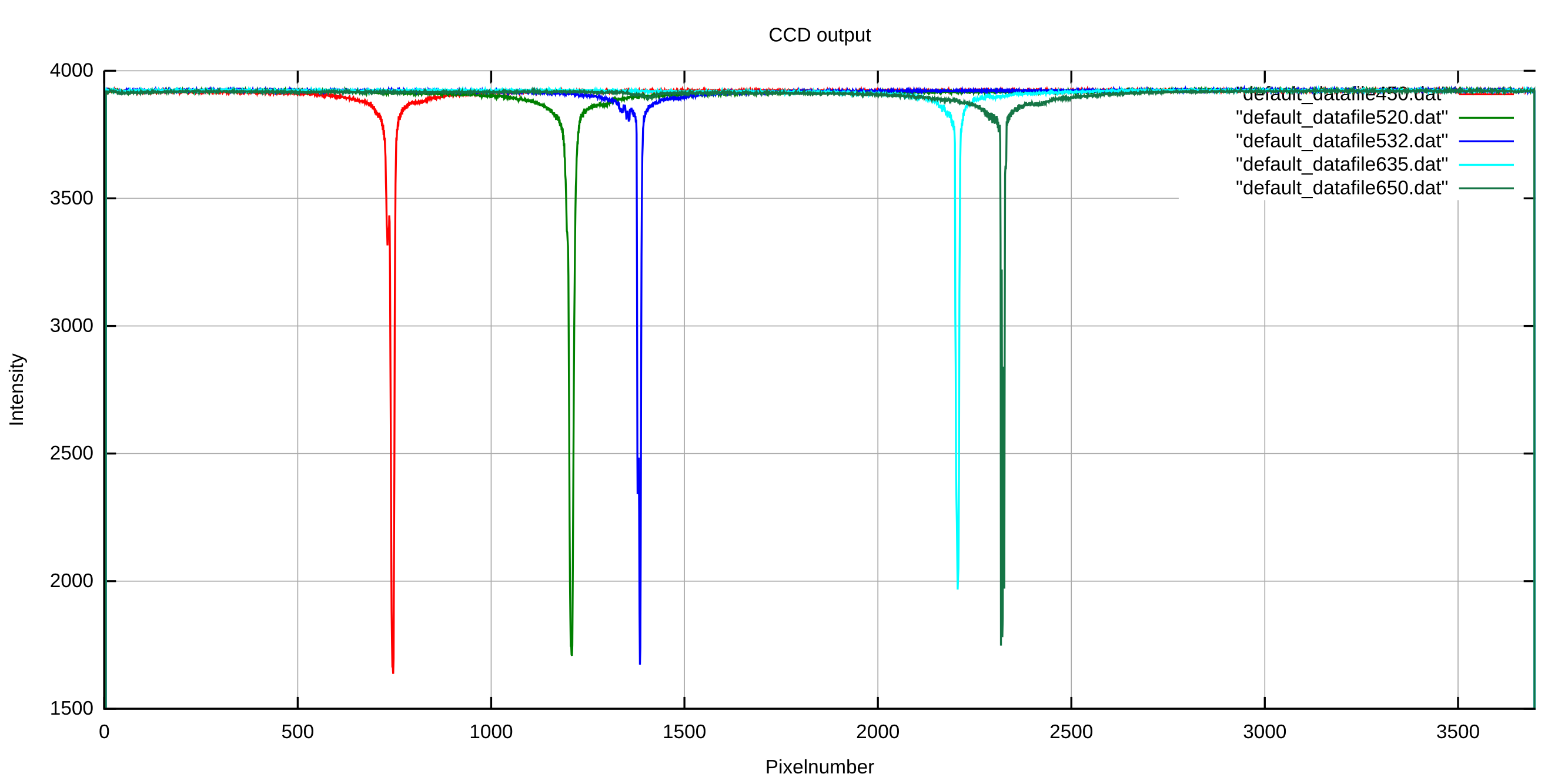
    This morning after my girlfriend had left for work I recorded the lines from five different laser pointers. As I've still not come around to do any data handling in the software for the Linear CCD module, the data is upside down as usual. In short and for those who might have forgot, the TCD1304 outputs around 1.5V for a saturated pixel and 3.5-4V for an unexposed pixel, hence the scale on the y-axis.

    It took a very short while to find the proper integration times. The 450, 520, 532 and 635 nm lasers were recorded in 40 µs. The 650 nm laser had an integration time of 143 µs. They're all supposed to be 5 mW, and they were not the cheapest laser pointers I could find, so I guess the batteries in the 650 nm are dying.

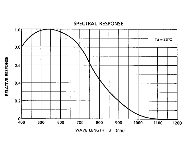
    That or it's the spectral response of the CCD playing a part (or both of course), but looking at the spectral response curve I'd go with the batteries.

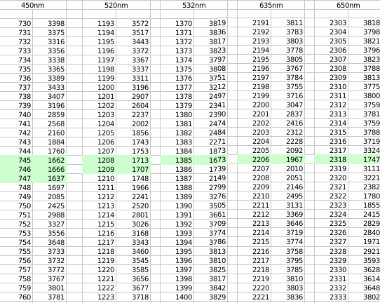
    In the spectra it's a bit hard to see just exactly how well (or poor) the focusing is. It's also a matter of the slit width of course. Here's a cut-out of selected regions of the acquired data (pixel number on the left, CCD output on the right):

    It looks like the sensor is more properly focused at the longer wavelengths. The 532 nm laser being a DPSS is the only proper laser - proper in the sense that it has a more well defined emission than the diode lasers - still it's not one line. Read more about that here: https://erossel.wordpress.com/2015/07/26/clear-as-the-mississippi/

    All in all I'm quite satisfied with the results, and for this cheap spectrometer, I don't think I'll bother doing a better job of focusing.

  • Click-on accessories

    esben rossel06/15/2016 at 07:25 0 comments

    While 99% of the measurements I do with spectrometers involve spectroscopic cells it'd be nice to have the possibility to connect other sample-accessories to the spectrograph.

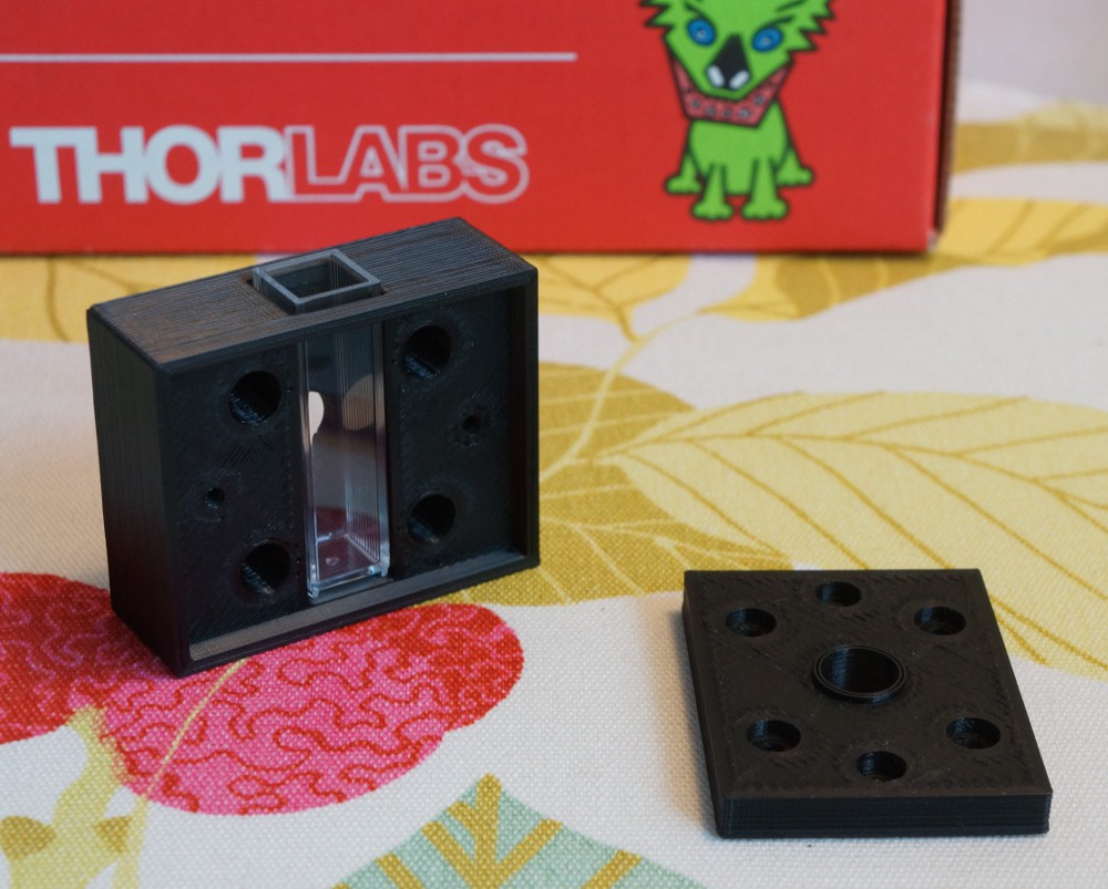
    Enter the magnetic click-on sample-holder:

    Sorry for the product placement, I just love these little labsnacks boxes I receive everytime I tear a hole in my wallet.

    As you see this is for a standard 10x10mm spectroscopic cell. I will eventually make a click-on accessory for reflective measurements. I still haven't figured out exactly how to attack this problem, but It won't be the usual integrating sphere..

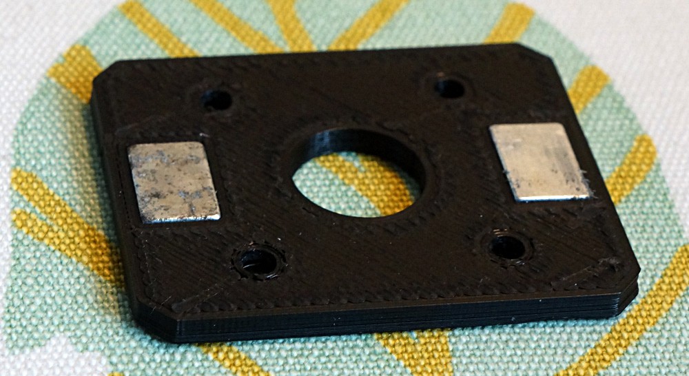
    The magnets are neodymium magnets I have in excess from everytime one of my bike lights break:

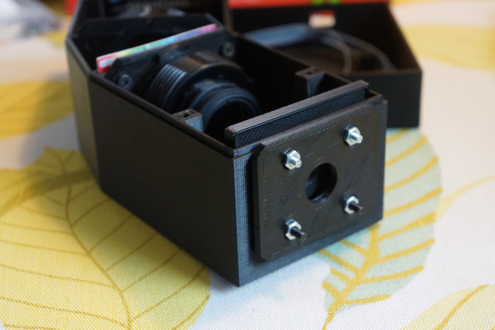
    Magnets mounted on the spectrograph:

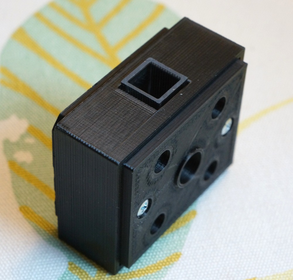
    Everything I have so far assembled with the spectroscopic cell holder clicked on.

    The magnets have a quite tight grip on the cell holder even if they only catch onto the two screws in the second picture. I also tried with two sets of magnets, but the force required to separate them seemed excessive. I may change my mind about this once I get around to constructing the light source (which will be just a Maglite 2AA xenon replacement bulb and a collimating lens from an old dvd-burner).

    In case you haven't noticed I'm slightly proud of this magnetic solution, even if I stole it from Thorlabs or Edmund optics or whoever.

    SCAD files can be found in the files section asap..

  • A very preliminary test of resolution

    esben rossel06/06/2016 at 20:22 2 comments

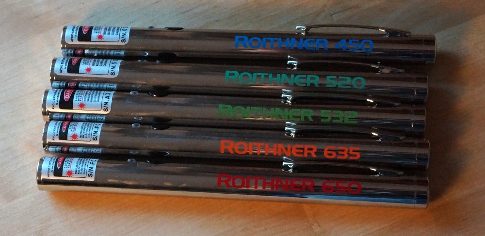
    I recently acquired a few good laser pointers in a collecting frenzy:

    My five new better quality laser pointers.

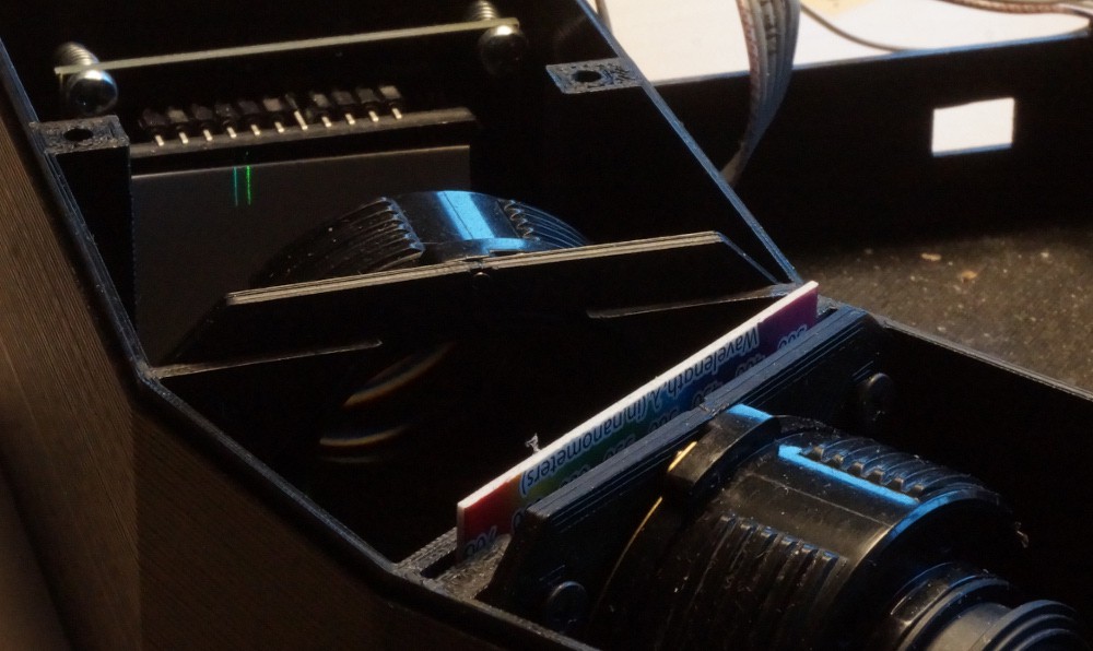
    I can't use all of them for work at the same time, so I figured I would try and see what kind of performance I can expect from the OtterVIS LGL. After carefully focusing an improvised slit with two razors taped on a piece of cardboard, using a mirror for autocollimation, I learned the box is 3 mm too short. But I also got this:

    These are the two reds. There are roughly 15nm between the two lasers. It's not as easy to see the red lines compared to the green ones below, I guess the camera's Bayer filter has a part in this.

    The two green lasers. They are app. 12nm apart. As you can see there's better resolution at lower wavelengths.

    The results are better than I expected. Of course this not proof of the resolution of the spectrometer, but it leaves me optimistic. I've done no effort to focus the diffracted light, and I've not done any readings with the CCD.

    Right now I'm speculating if some clever use of Scheimpflug principle can improve the separation in the red part of the spectrum.

  • Waiting for the new CCD-PCB

    esben rossel04/05/2016 at 17:24 0 comments

    This is the first log, so here's an update on everything done:

    The design of the spectrograph is done.

    And everything missing:

    The old PCB's I have for the linear CCD module don't fit inside the OtterVIS LGL, so I'm waiting for the newer smaller version.

    The cuvette-and-light-source assembly is still in development - or rather it needs to be developed.

    The same goes for the slit. It's going to be comprised of two razor blade edges held together with magnets, but I need to figure out exactly how to couple it to the spectrograph.

View all 7 project logs

  • 1
    Step 1

    Print the spectrograph

    1. Download the spectrograph scad files.
    2. If you're using a different grating modify the angle "1st" in both files. If you use different lenses modify the parameter "ff" in both files.
    3. Make sure the screw-holes match the TCD1304 PCB you have (there are two SMD versions of the PCB).
    4. Print the spectrograph and the lid.

    NB: It takes around 18h to print the spectrograph, so go get drunk or something in the meantime.

  • 2
    Step 2

    The linear CCD module

    1. Goto https://hackaday.io/project/9829-linear-ccd-module
    2. Populate the TCD1304 PCB. However you may want to put T1 on the same side as the CCD and solder the cable directly onto the PCB. There's not a lot of space inside the OtterVis LGL box.
    3. Insert the PCB in the spectrograph. NB: Hex-screws will be much easier to deal with than philips head screws.
  • 3
    Step 3


    Stripping the lenses:

    While the Pentax SMC-A 50mm f/2 are small, they need to be stripped from all their extra weight.

    1. Unscrew and remove the bayonett.
    2. Unscrew and remove the aperture coupling together with any screws you find.
    3. Unscrew front ring.
    4. Again remove any screws you come by.
    5. Remove the front lens group.
    6. Remove the aperture iris.
    7. Remove the lens barrel from the focusing helicoid.
    8. Reassemble the front and back lens groups, and you should have something like the picture above.

    You can also watch this video (not mine) on youtube: Pentax SMC-A 50/2 disassembly. Be advised that for this project you won't need any spanner wrenches, so if you find yourself in need of that, you're going too far..

    Download and print the lens holders. Insert the lenses in the lens holders and secure them using the left-over screws. Finally insert the lenses in the spectrograph.

View all 4 instructions

Enjoy this project?

Share

Discussions

Sarah Alexander wrote 07/09/2019 at 11:11 point

Thank you so much for sharing your work! It has been extremely helpful. Can I ask, how did you select the dimensions of the input slit?

  Are you sure? yes | no

esben rossel wrote 07/09/2019 at 21:43 point

Hi Sarah. Thx for the nice words. The inner diameter of the ring magnet set the limit for the length of the slit (I guess any thing larger than a couple of mm's will do, but a long slit will make it easy to hit the sensor regardless how poor your alignment is). The width was determined by how close I was able to push two pieces of DE razor-blades together (a very thin piece of paper between the blades was helpful). I measured the width of the slit by stuffing into my old photographic enlarger and simply measure the width of the projected image of the slit. Esben

  Are you sure? yes | no

David H Haffner Sr wrote 08/04/2016 at 16:49 point

Hey esben, well thanks for checking it out, the spectral bandwidth is quite correct, for mine, the Plab as it stands is 2 - 3nm,  if I could collimate the light coming from the slit to the camera I could get to 1nm, but I couldn't keep the present forward facing geometry configuration.

So there is still work to do but I am getting there, looks like you are too!

  Are you sure? yes | no

David H Haffner Sr wrote 08/02/2016 at 21:30 point

Well, if anyone has been paying attention to my project, I have already achieved 1.6nm spectral resolution with the Plab kit that I have heavily modified.

  Are you sure? yes | no

esben rossel wrote 08/04/2016 at 16:09 point

I've been paying attention to your project with curiosity :)

  Are you sure? yes | no

Ed0 wrote 08/02/2016 at 18:04 point
How does this compare to Public Lab's Do-It-Yourself spectrometry kit? https://publiclab.org/wiki/spectrometer It is capable of better than 3 nanometer spectral resolution and can record light from ~390 to ~900nm and costs $45 for one.

  Are you sure? yes | no

esben rossel wrote 08/04/2016 at 16:08 point

I don't have a Public Lab DIY spectrophotometer, so I can't say for sure. But looking at the page you link to I'd say the key differences are:
1) The TCD1304 is 29.1mm vs PLab's 5mm

2) The TCD1304 pixelsize is 8x200 µm, vs 2.2x2.2 µm

3) The imaging lens is a well corrected high quality lens focused at infinity. I can't figure out what the PLab's imaging lens is.

4) The light from the slit is collimated with a lens. In the PLab's the collimation is approximative - and it may be quite acceptable.

Once I get close to the spectral lamps at my high school, I can be more specific about the actual resolution of my spectrophotometer.

  Are you sure? yes | no

Sandeep Kumar wrote 08/02/2016 at 11:54 point

@esben rossel What are you using for plotting the data?

  Are you sure? yes | no

esben rossel wrote 08/04/2016 at 15:53 point

So far I'm simply using gnuplot

  Are you sure? yes | no

helge wrote 06/12/2016 at 09:17 point

>> While the Pentax SMC-A 50mm f/2 are small, they need to be stripped from all their extra weight.
As a hobby photographer I'm sad to see a great project that still has these "dooh you first gots to first break stuff" instructions. Most interchangeable camera lenses have a filter thread. Reverse lens adapters are available for improvised macro photography and "UV"/"anti-haze" protective filters are cheap. Just remove the glass and glue the metal ring to the adapter plate.

If you want to keep the part count low, a polygonal ring can be included in the adapter plate surface, metal lens filter threads will easily self-tap their way into them. The polygonal shape (<60 facets) is easier to cut than a smooth cylindrical protrusion.

Better still would be to mount the lens by the bajonet because the flange-to-film distance is defined by the camera system, all other distances are not. You'll also regain focusing capability.

  Are you sure? yes | no

helge wrote 06/12/2016 at 09:43 point

Oh and by the way, it's better to have the rays slightly tilted out of the horziontal plane which will shift the lens flares out of the CCD AOI.

While you're at it, add a thin metal plate with a 1-2mm hole drilled into it behind the slit. blacken it with candle soot. This will cut out most of the light that doesn't hit the sensor anyway and avoids inverse slit images being formed by the slit rear side being illuminated with scattered light.

These two steps should lead to a noticable improvement in signal to background

  Are you sure? yes | no

esben rossel wrote 06/12/2016 at 10:41 point

This is sound advice. I will keep it mind.

  Are you sure? yes | no

esben rossel wrote 06/12/2016 at 10:39 point

I think you missed the point. The idea of stripping the lenses down to the barrel is to be able to fit everything inside the print volume of the 3D printer. 

I'm an amateur photographer myself and if these lenses had been rare or otherwise special you can bet I would have found another solution, but these are cheap ubiquitous lenses and not expensive overpriced german glass, Nikon Rayfacts with extraordinary transmission characteristics or large format lenses with airbraked shutters instead of gear trains, so I really don't feel bad about repurposing them.

It would have been nice to be able to use the bayonet for the same point you mention, there was just not room for it.

  Are you sure? yes | no

helge wrote 06/12/2016 at 12:02 point

Hi, thanks for the response. I might have overlooked that fact, sorry for that. 

I've recently started using Ensat S-302 self-tapping threaded inserts for my 3D printing work. they are pretty awesome and incentivize modular design. 

A modular design would add a little complexity for the benefit of being able to separately print, optimize and modify the optical path.

  Are you sure? yes | no

esben rossel wrote 06/12/2016 at 12:41 point

I will have to look up those inserts, they sound like a better solution than to simply force a threading directly in the plastic.

Modular is definitely the way to go, it's a PIAS to assemble everything and then realize it has to be taken apart because of some detail. That's for the next project ;)

  Are you sure? yes | no

Chase wrote 05/07/2016 at 02:15 point

Pretty cool stuff, I'll be very interested to see what type of accuracy you're achieving.  If you're getting within 5nm I'll have to give this a shot.

  Are you sure? yes | no

esben rossel wrote 07/01/2016 at 08:59 point

Hi Chase. I believe I'm well within 5nm. Take a look at the log "Recordings of laser lines".

  Are you sure? yes | no

Similar Projects

Does this project spark your interest?

Become a member to follow this project and never miss any updates