esben rossel
-
Other lenses
08/31/2017 at 06:06 • 0 commentsI've used Pentax SMC-A/M 50mm f/2 lenses for the OtterVIS, but of course others will work as well.
This week I got my hands on two different 50mm Olympus lenses. Here are some thoughts on them:
The very easy to find Zuiko 50mm f/1.8 is not really very suitable. Once taken apart, the lens barrel isn't much smaller than the lens in it's entirety.
The less abundant Olympus PF 50m f/2 is a different story. Once removed from the focusing helicoid, the lens barrel is quite small. And it's almost as if it's made to be taken apart. There are very few screws to remove and the lens groups are held together with holders with bayonetts. One drawback is that there are no screw holes to secure the lens to spectrometer.
The lens is from the 'power focus line' (hence the PF designation) and the demand for them is small since they are virtually unusable as manual focus lenses, so if you can find them they are likely to be much cheaper than their predecessors. Without knowing for sure, I'd say the optics are identical to the venerable Zuiko 50/1.8. -
Sodium and mercury
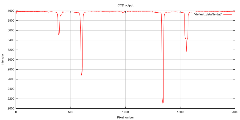
02/07/2017 at 17:59 • 0 commentsHg spectral lamp:
![]()
The line at pixel no. 1340 is mercury's emission at 546.0 nm. At pixel no. 598 is the 435.8 nm line.
It's not entirely accurate to assume a linear relationship between wavelength and pixel no but let's assume that tan θ is linear for small intervals (and here we're talking about a difference of 6.4° of θ for the diffracted light for the two lines). That gives 0.15 nm / pixel.
Of course I'm not getting a resolution like that.
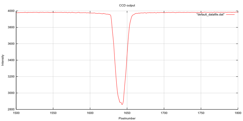
Here's a capture of a Na spectral lamp:
![]()
It's supposed to be two lines at 589.0 nm and 589.6 nm. If you really want, you can sort of persuade yourself that there's a hint of two lines here. But they are really not resolved.
Maybe it's the focusing, maybe it's the plastic grating, maybe it's my sticky fingers on the CCD. Whatever it is, it's smearing the picture.
Let's go back to the CFL-test of the weekend:
With the "calibration" with the Hg-lamp we can now say that he two lines at around pixel no. 1325 and pixel no. 1352 are 4.0 nm![]()
apart. (I'm not sure I can afford the .0 in this statement). But it's safe to say that the resolution of the spectrometer is somewhere between 1-4 nm.
-
CFL test
02/05/2017 at 13:54 • 0 commentsI've been so busy trying to learn the basics of linux tty, that I forgot to follow up on this project.
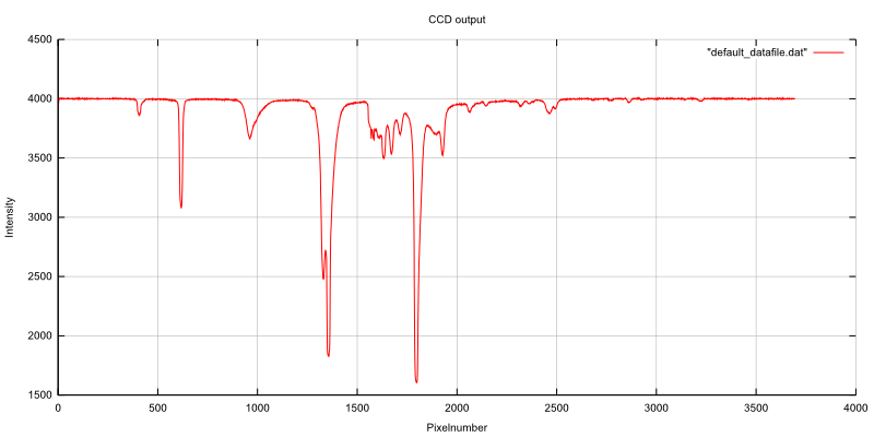
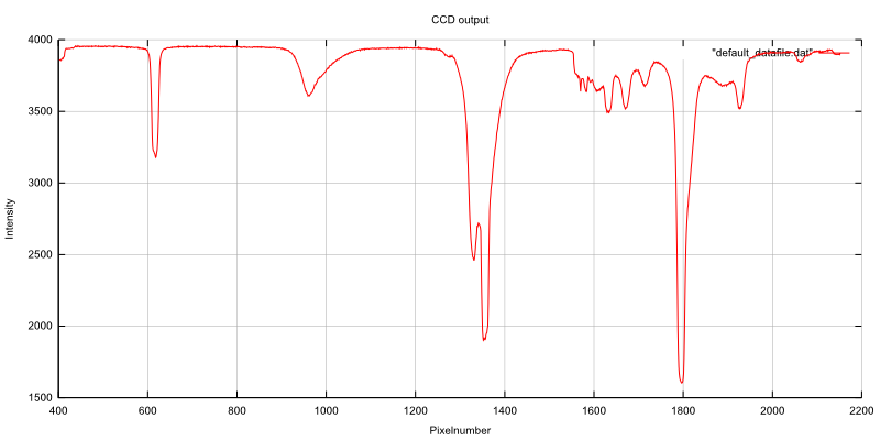
Someone asked about a CFL-spectrum and here it is:
![]()
I don't have a reference spectrum to compare with, but my 532nm laser pointer gives a peak at around 1250 pixels, so I guess the peaks at 1350 pixels is the 542.4 nm terbium line and 546.5 nm mercury line.
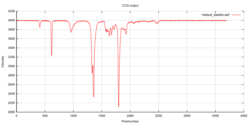
I took the liberty of zoomin in:
![]()
The "lines" are a bit round, so I guess I could do a better job with the focusing.
Next week in the universe. Tests with the spectral lamps at work..
-
Recordings of laser lines
07/01/2016 at 08:25 • 4 commentsThe construction of the spectrometer is close to an end. Yesterday I spent the afternoon doing my best to focus the diffracted light onto the CCD. It's not as easy as collimating the slit - there are no tricks with mirrors that I know of.
By eye (and with a ruler), I simply tried to estimate the distance from the imaging lens that a 532 nm laser pointer would produce the most well defined line on a piece of paper, and then position the CCD at this position.
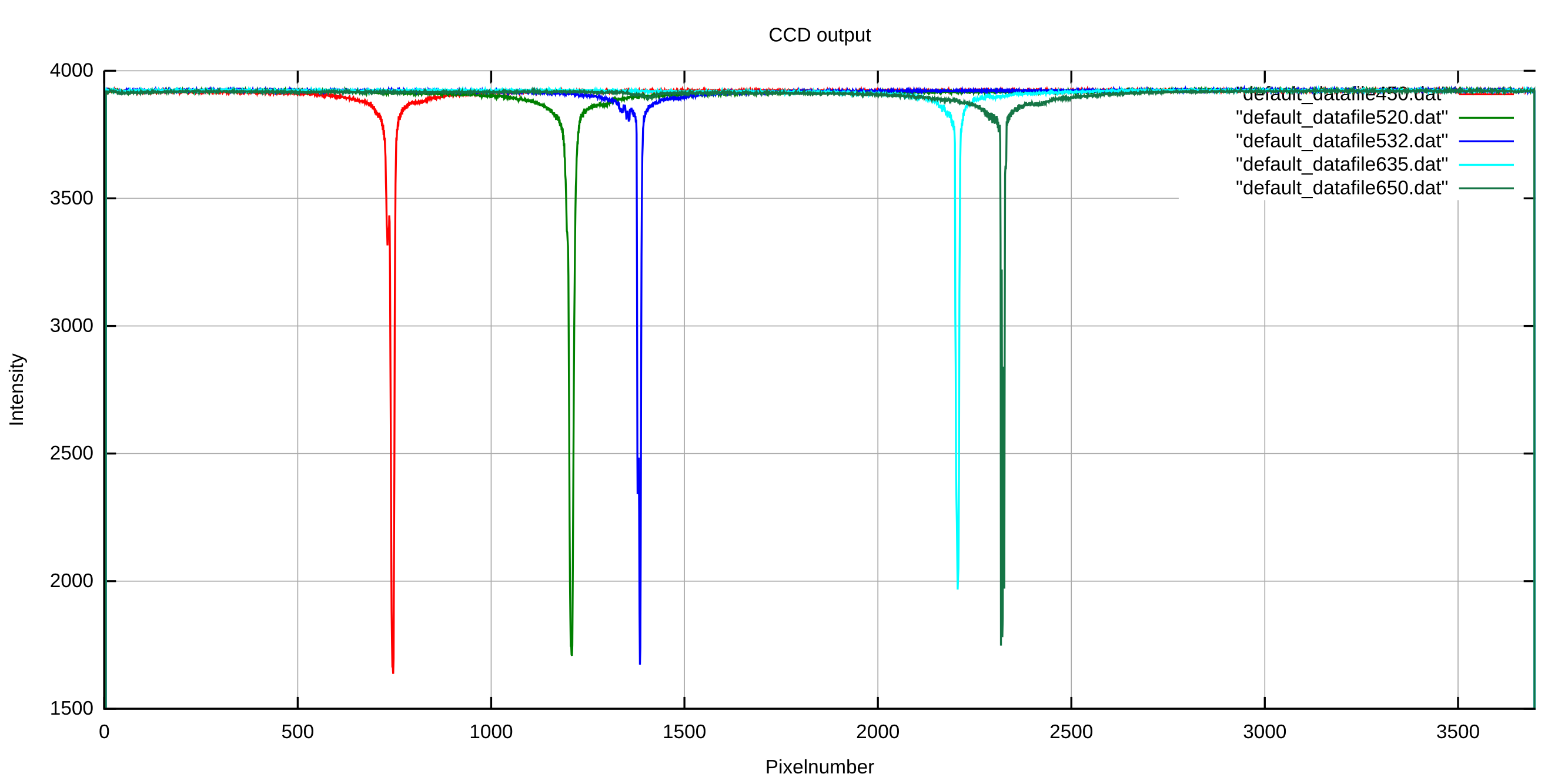
This morning after my girlfriend had left for work I recorded the lines from five different laser pointers. As I've still not come around to do any data handling in the software for the Linear CCD module, the data is upside down as usual. In short and for those who might have forgot, the TCD1304 outputs around 1.5V for a saturated pixel and 3.5-4V for an unexposed pixel, hence the scale on the y-axis.
![]()
It took a very short while to find the proper integration times. The 450, 520, 532 and 635 nm lasers were recorded in 40 µs. The 650 nm laser had an integration time of 143 µs. They're all supposed to be 5 mW, and they were not the cheapest laser pointers I could find, so I guess the batteries in the 650 nm are dying.
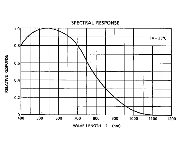
That or it's the spectral response of the CCD playing a part (or both of course), but looking at the spectral response curve I'd go with the batteries.
![]()
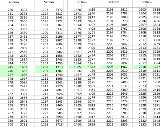
In the spectra it's a bit hard to see just exactly how well (or poor) the focusing is. It's also a matter of the slit width of course. Here's a cut-out of selected regions of the acquired data (pixel number on the left, CCD output on the right):
![]()
It looks like the sensor is more properly focused at the longer wavelengths. The 532 nm laser being a DPSS is the only proper laser - proper in the sense that it has a more well defined emission than the diode lasers - still it's not one line. Read more about that here: https://erossel.wordpress.com/2015/07/26/clear-as-the-mississippi/
All in all I'm quite satisfied with the results, and for this cheap spectrometer, I don't think I'll bother doing a better job of focusing.
-
Click-on accessories
06/15/2016 at 07:25 • 0 commentsWhile 99% of the measurements I do with spectrometers involve spectroscopic cells it'd be nice to have the possibility to connect other sample-accessories to the spectrograph.
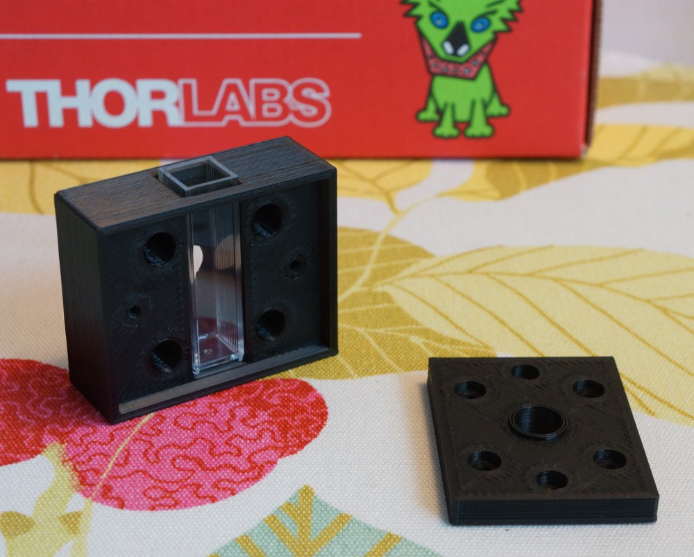
Enter the magnetic click-on sample-holder:
![]()
Sorry for the product placement, I just love these little labsnacks boxes I receive everytime I tear a hole in my wallet.
![]()
As you see this is for a standard 10x10mm spectroscopic cell. I will eventually make a click-on accessory for reflective measurements. I still haven't figured out exactly how to attack this problem, but It won't be the usual integrating sphere..
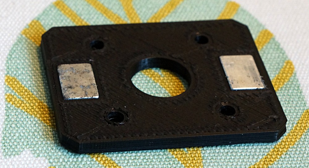
The magnets are neodymium magnets I have in excess from everytime one of my bike lights break:
![]()
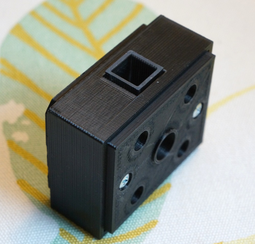
Magnets mounted on the spectrograph:
![]()
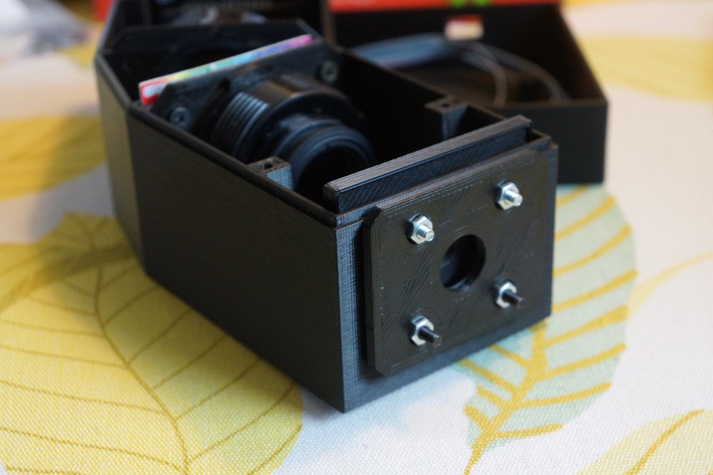
Everything I have so far assembled with the spectroscopic cell holder clicked on.
![]()
The magnets have a quite tight grip on the cell holder even if they only catch onto the two screws in the second picture. I also tried with two sets of magnets, but the force required to separate them seemed excessive. I may change my mind about this once I get around to constructing the light source (which will be just a Maglite 2AA xenon replacement bulb and a collimating lens from an old dvd-burner).
In case you haven't noticed I'm slightly proud of this magnetic solution, even if I stole it from Thorlabs or Edmund optics or whoever.
SCAD files can be found in the files section asap..
-
A very preliminary test of resolution
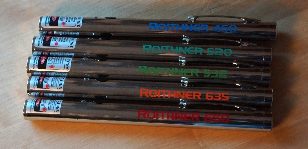
06/06/2016 at 20:22 • 2 commentsI recently acquired a few good laser pointers in a collecting frenzy:
![My five new better quality laser pointers.]()
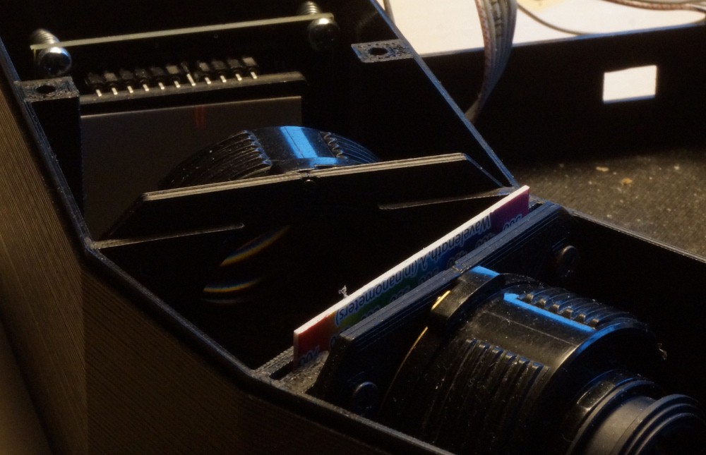
I can't use all of them for work at the same time, so I figured I would try and see what kind of performance I can expect from the OtterVIS LGL. After carefully focusing an improvised slit with two razors taped on a piece of cardboard, using a mirror for autocollimation, I learned the box is 3 mm too short. But I also got this:
![]()
These are the two reds. There are roughly 15nm between the two lasers. It's not as easy to see the red lines compared to the green ones below, I guess the camera's Bayer filter has a part in this.
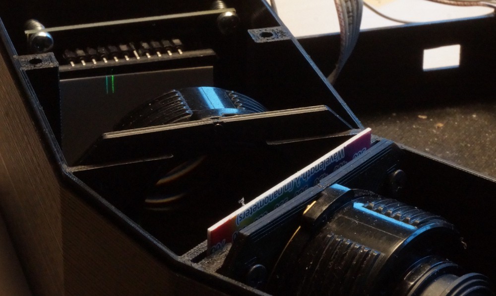
![]()
The two green lasers. They are app. 12nm apart. As you can see there's better resolution at lower wavelengths.
The results are better than I expected. Of course this not proof of the resolution of the spectrometer, but it leaves me optimistic. I've done no effort to focus the diffracted light, and I've not done any readings with the CCD.
Right now I'm speculating if some clever use of Scheimpflug principle can improve the separation in the red part of the spectrum.
-
Waiting for the new CCD-PCB
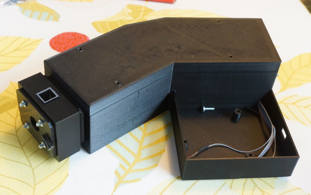
04/05/2016 at 17:24 • 0 commentsThis is the first log, so here's an update on everything done:
The design of the spectrograph is done.
And everything missing:
The old PCB's I have for the linear CCD module don't fit inside the OtterVIS LGL, so I'm waiting for the newer smaller version.
The cuvette-and-light-source assembly is still in development - or rather it needs to be developed.
The same goes for the slit. It's going to be comprised of two razor blade edges held together with magnets, but I need to figure out exactly how to couple it to the spectrograph.
OtterVIS LGL spectrophotometer
A super cheap decently resolving open source VIS-spectrophotometer. The cheapest in the OtterVIS line.