-
Go-Go-Gadget nRF24L01+
08/10/2014 at 05:02 • 0 commentsYou know how sometimes you can take a device, plug it in, and it works exactly like you hoped the very first time? I wish I could say that happened for me with the nR24L01+ wireless module, but alas, for me, it was not meant to be.
There were far too many variables involved, and far too much new ground to cover, such that it was inevitable I would learn things the hard way. On the positive side, by doing everything wrong the first time and solving each issue one at a time, I am now that much more familiar/comfortable with this wireless module and the MSP430 and Raspberry Pi libraries for it. I also have a greater appreciation for how minimal and well-designed the nR24L01+ wireless module interface is; while the numerous registers and instructions seemed daunting at first, they actually provide a well-balanced capability for a wide range of wireless setups.
I'm very happy to report now that I have successfully transmitted data from my Raspberry Pi (running a Python 3 Program) to my MSP430 Launchpad (using MSP430G2553) wirelessly using nRF24L01+ modules! The code involved still shows a few battle scars from my debugging, but I should be able to clean it up and upload each program to GitHub so that anyone else can just download & run the code with minimal effort (note that there are still some setup steps for the Raspberry Pi that I'll detail, but at least the wireless configuration settings will match work right out of the box). Just a few of the issues I ran into while debugging were mismatched payload length, mismatched channel assignments, swapped pinouts, and backwards address byte order.
At this point, I'm able to send data:
- from a Python app running on laptop via telnet to a Python app running on my Raspberry Pi
- from a Python app running on my Raspberry Pi to my MSP430 (verified via debugging data)
- from my MSP430 to the strand of WS2812B LEDs
While I've been using dummy data for the most part, at this point, I feel (personally) that the most significant risks have been mitigated as those were the main first time events for me. Going forward, I just need to take what I've done and work it into handling the actual data. Risks still remain, like bandwidth, timing (the MSP430 doesn't have the memory to store data for 200+ LEDs), and even power (the LED strand power traces may be undersized for the current at max load), but at least now I know that everything in my prototype system is hooked up properly and I can at least proceed with circuit board schematics, layout, and fabrication. Today is a good day.
-
Light ‘em up!
07/15/2014 at 06:26 • 0 commentsWith the waterfall part of the project working reasonably well, I’ve moved on to the electronics side of the project, beginning with control of the WS2812B LEDs.
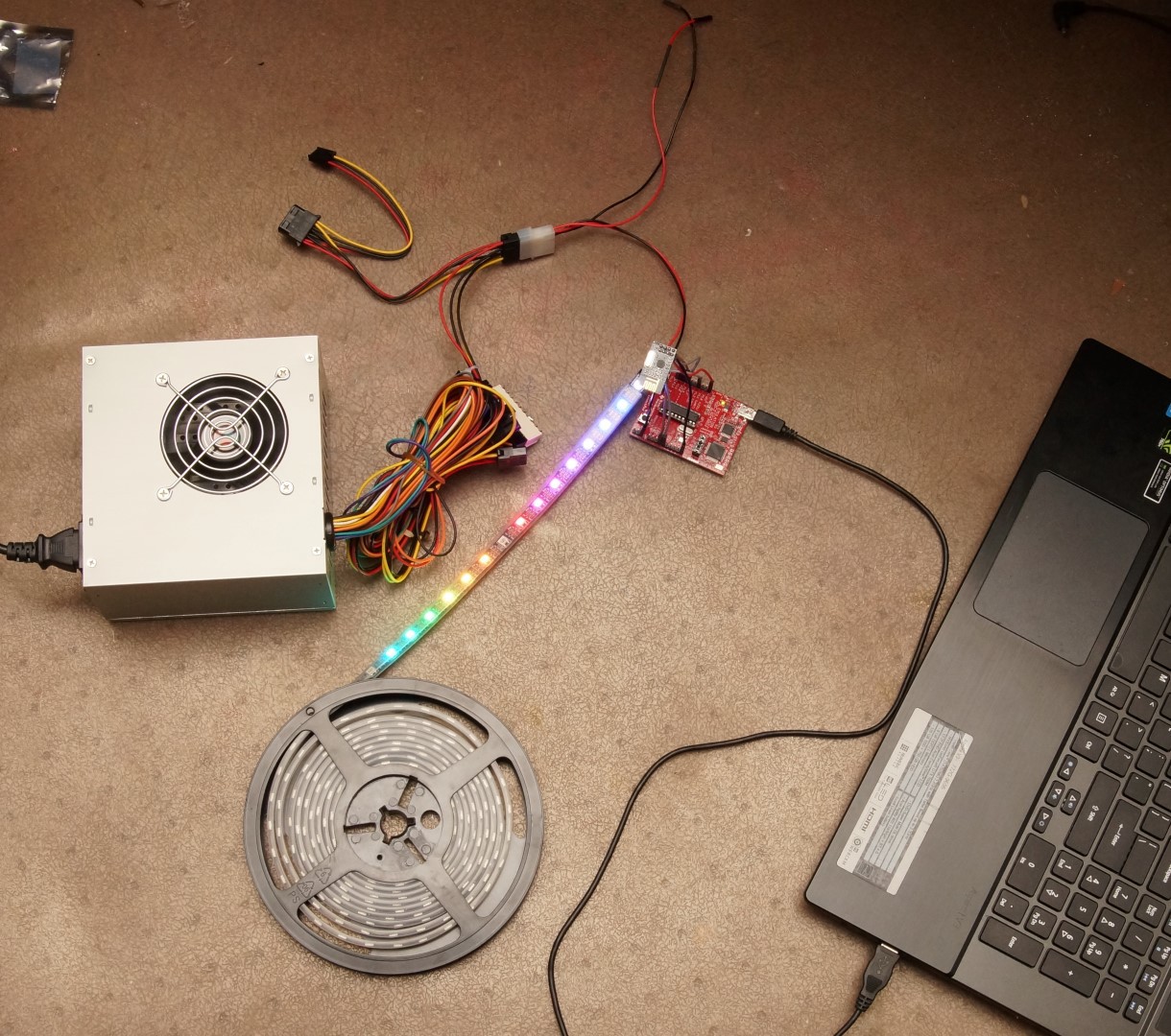
To power the LEDs, I found it convenient and cheap to use an ATX power supply. At full power, each LED can consume up to 50mA, so for 200 LEDs that means I would need at least 10A at 5V. An ATX supply that can do this can be purchased for as little as $14 or salvaged for free.
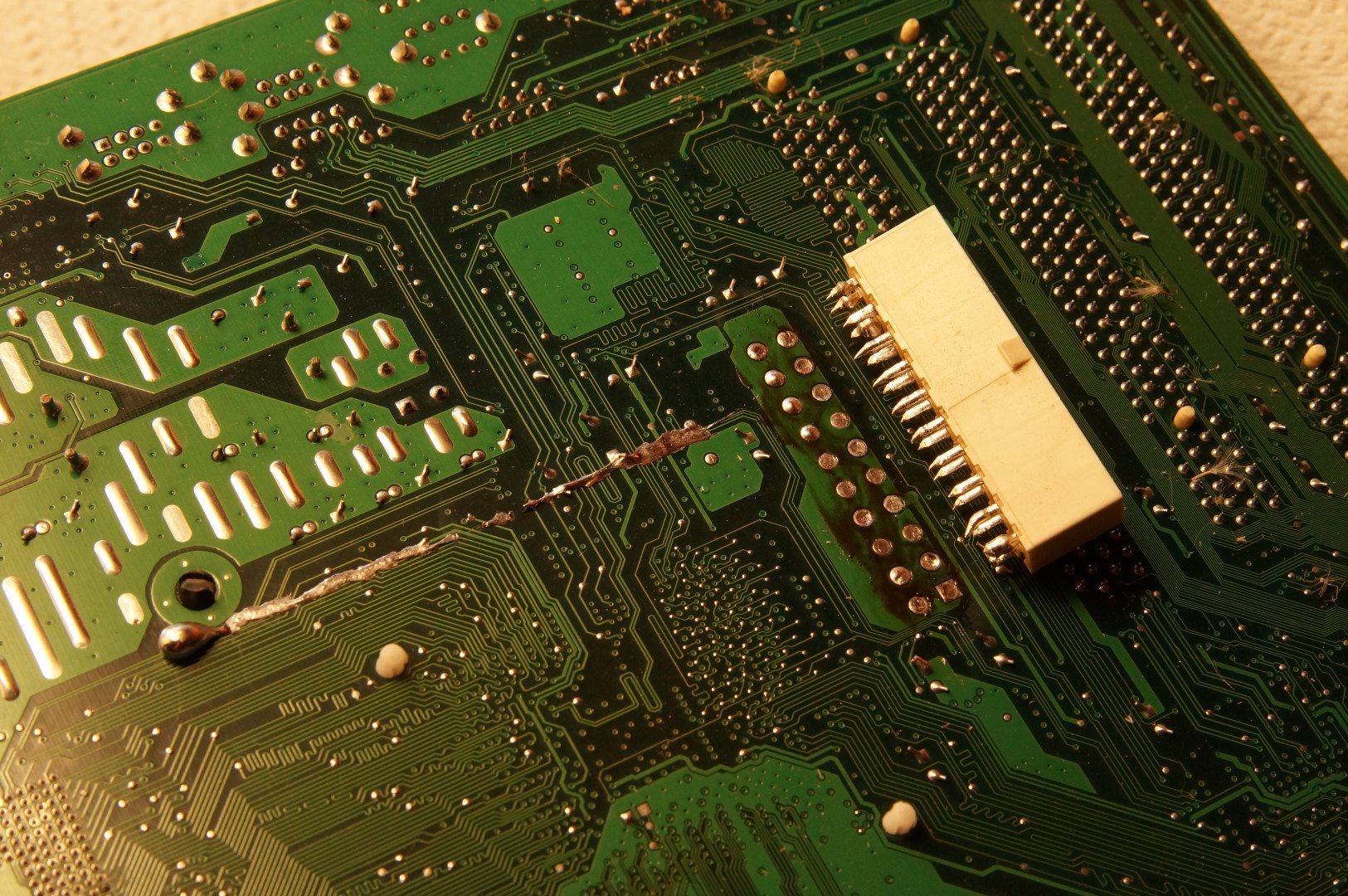
I plan to take apart the power supply later; if there is enough room inside, I may use it to house the final electronics as well. ATX power supplies need one of the pins pulled low to start operating (aside from standby power), so I created a shorting jumper by removing the ATX connector from an old motherboard and just soldering a wire to pull down the control pin. My preferred technique for connector removal is to add excess solder to the back of the thru-hole pins of the connector and slide a soldering iron back and forth along them to evenly heat up all the pins. After working it for a minute or two, the connector fell right out, and I used some desoldering braid to clean up the pins.
The next step was to find a good way to communicate with the WS2812B LEDs. I wanted to use the MSP430G2553 microcontroller, as it comes with the low cost MSP430 Launchpad. I found a few resources which helped--some used the same microcontroller but older versions of the LED (e.g. WS2811) and some used the WS2812B LED but also used a more advanced MSP430 microcontroller. I decided to use the code designed for the more advanced microcontroller and port it back to work with the MSP430G2553. As it turns out, there were some differences with register names and available clock settings, but after getting acquainted with the MSP430 communication protocols and making some edits to the code, it worked!
![]()
I've forked the original code and uploaded my changes to github here. Note that currently there is a limited to how many LEDs can be controlled because a buffer is used to store all the pixel data, and there is not much RAM for such a buffer on the MSP430G2553. I’m hoping when it is all working I can just stream the pixels in real time, mitigating the need for large data buffers.
-
I gotta have more cowbell...er...waterpump!
06/08/2014 at 22:22 • 0 commentsThe new pumps came in! I tried them out and they produce a much more satisfying flow. There are a few places where the water still groups together into streams, so I may investigate adding more holes or increasing hole sizes in those areas. Add that to the to-do list.
I then cut and drilled tubing for the second trough; the process was very similar to the first one, but I happened to find a small leak in one of the 3D over-the-edge parts. Something else to add to the to-do list…
I wanted to improve upon the duct tape solution to redirect water into the trough at the edges. I came up with the 3D model seen here at Thingiverse. It provides a small channel to catch the water coming down, and then it redirects water away from the edge, widening as it gets closer to the surface of the water. I superglued this piece onto the bottom corners of the glass and sealed it along the glass-plastic surface with a small amount of Silicone II.
It works well for the most part, but there is the occasional stream of water that makes it over the edge and gets the wood wet; I’ll probably add a little more material to the surface to help contain all the water. I may need more paper for my to-do lists. :)
The "wood that gets wet" is 1 inch corner edging. It covers the rather unsightly edge of the plastic sheeting liner. A little backstory here....
The liner is made out of two layers of 6mil plastic, and a black top layer made by cutting open a 3mil thick garbage bag (I really don’t want it to leak, so redundancy is critical). I filled the liner with water, then trimmed the plastic layers so that they ended at the top edge of the wood trough. I then taped the layers together with duct tape all the way around the edge. I nailed the lining into place along the top edge of the wood (nailing through the duct tape) about every 6 to 8 inches along the edge. The corner edging wood covers the plastic sheeting edge, duct tape, and nails along the edge of the liner.
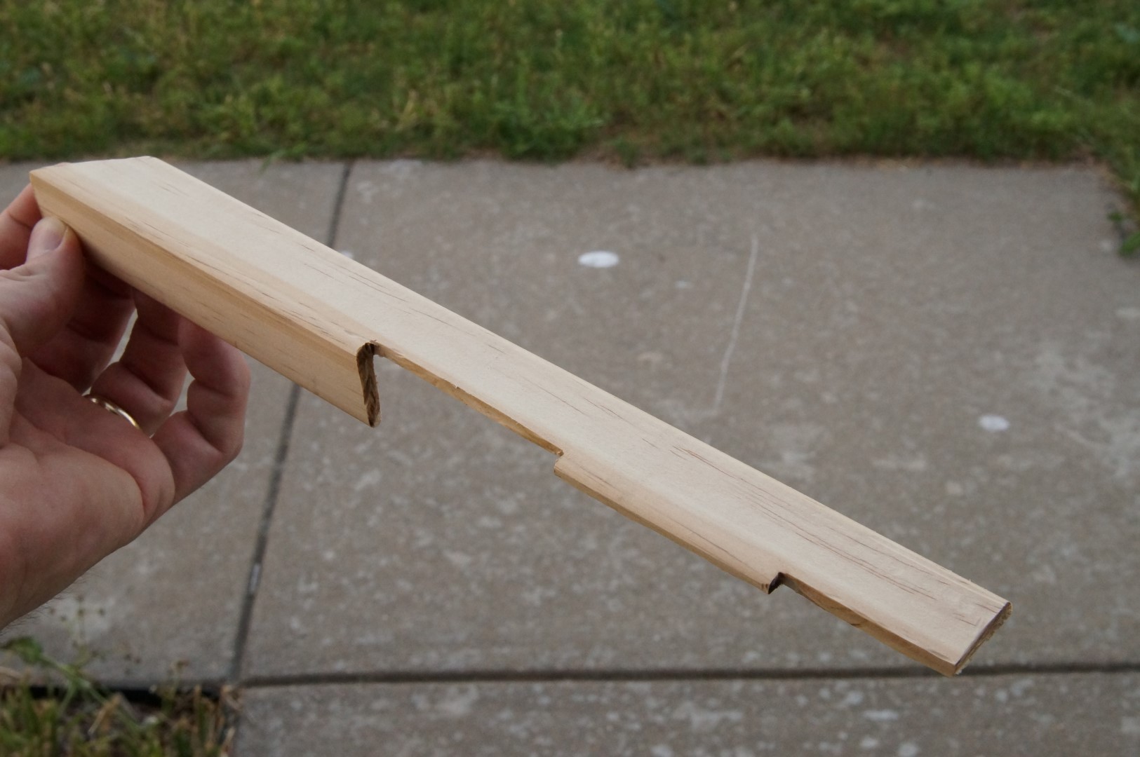
The wood corner edging on the long sides of the trough is rather straightforward to cut and doesn’t require anything special, but the ones along the short edges are rather oddly shaped. I marked the needed cuts with a pencil, and took a Dremel to it, revealing a final shape (which fits well) that looks like this:
One last thing, I uploaded the first video required for the Hackaday Prize! You can find it here, enjoy!
-
Pumps, hoses, clips, and....suds?
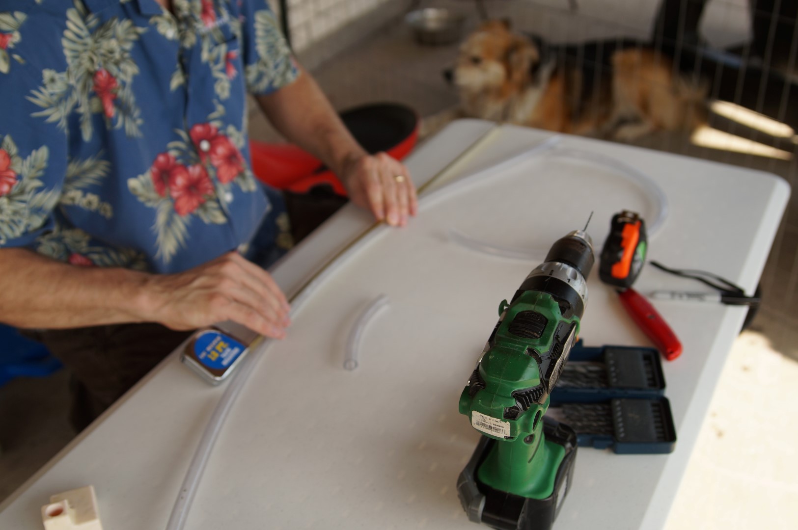
05/31/2014 at 22:43 • 1 commentI ordered two EcoPlus185 water pumps with an output of 158gal/hr and a head height of 4 feet. When they arrived, I placed one in the water trough and measured that I would need about two feet of vertical tubing. Across the top edge of the glass, I needed five and a half feet of tubing.
I cut both pieces of tubing, and then drilled the holes in horizontal tubing. I opted for a 1/16” drill bit and spaced the holes about a half inch apart.
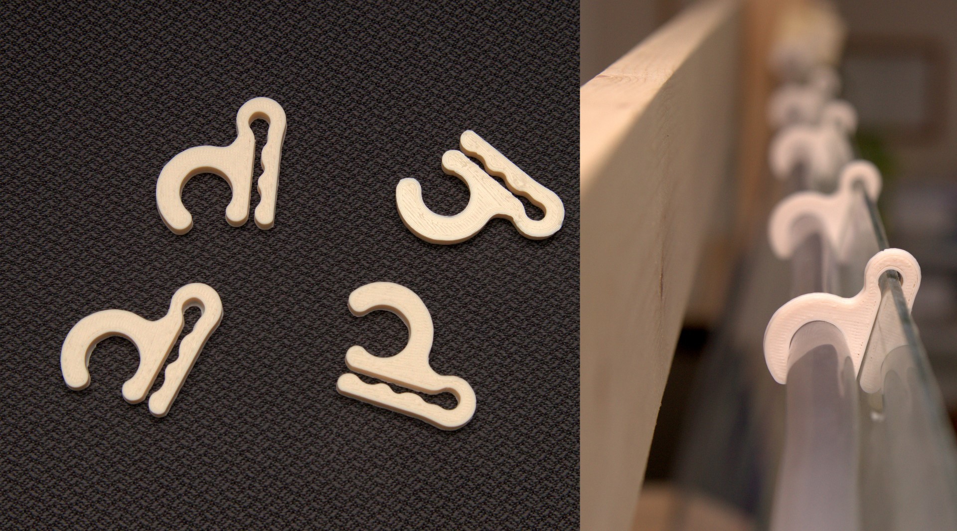
I assembled the tubing and a pump for one 6-foot section and added some Silicone II around the 3D-printed fittings to help minimize the probability of leaking around the back side of the glass. The silicone took a few hours to set, so in the meantime, I generated some 3D models of a hose clips to hold the horizontal hose along the top of the glass. After printing and testing them, I selected one that gripped the hose and glass best and printed a few more of them. The .STL file for the hose clip can be found here.
![]()
With the horizontal hose secured in place, I was ready for a test run. I plugged in the pump..water went up the hose…and started coming down the front of the glass! Alas, the excitement was short lived…While there wasn’t any water leakage, there were a few problems:
-The water flow was considerably better closer to the pump. In fact, the water didn’t even fill the horizontal tube at the far end, so apparently the flow rate was not high enough.
-The water wasn’t coming down the glass as a flat sheet, but would instead collect into small streams (not the effect I was hoping for).
-The shower glazing along the vertical edge of the glass kept the wood dry, but at the bottom where it ran off, some water landed on the top edge of the trough. I’ll need to find a way to redirect water inward (away from the edges) at the bottom of the glass; I’ll save this problem for a little later (a little duct tape will do the job in the meantime)...
I decided to try using both pumps in one trough (instead of the plan for one pump per trough) to see if it would help with the flow rate issues. I 3D printed a reversed version of the over-the-edge-3D-printed piece to use at the opposite end of the glass. After sealing it and testing with two pumps, the flow rate was somewhat improved but still less than I wanted. Also, the water continuedcollecting into streams as it flowed down the glass surface.
I resigned myself to ordering more powerful pumps, and opted for four PP29116 pumps (two per water trough). It is rated for 291gal/hr, and even at 2ft head height, will still provide 251gal/hr.
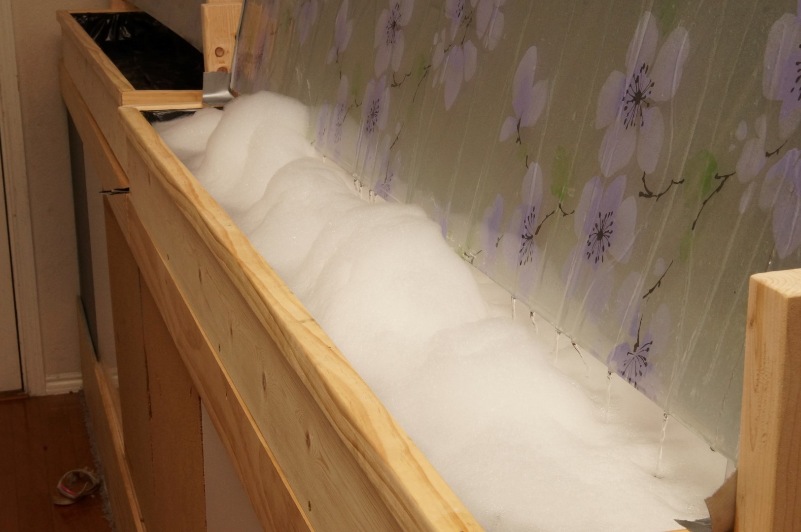
In the meantime, I thought I would try one more thing to get the water to flow in a nice sheet down the surface. I researched surfactants and decided to add a little laundry detergent to the water.
Turns out that was simply a bad idea…it just made a bunch of suds, and if you look closely, you can see the water continues to group into individual streams. After letting the kids play with the bubbles for a bit, I pumped out all the water and refilled the trough.
-
Water over the edge...
05/13/2014 at 07:38 • 0 commentsTo create a waterfall effect down the glass surface, I need to bring water up along the back side of the glass, come over the top edge of the glass, and then travel along the top edge of the glass. Trying to cobble something together from the myriad of pipe fittings sold in hardware stores ended up being a fiasco that would take up a lot of space, so I decided to model and 3D print what I really wanted.
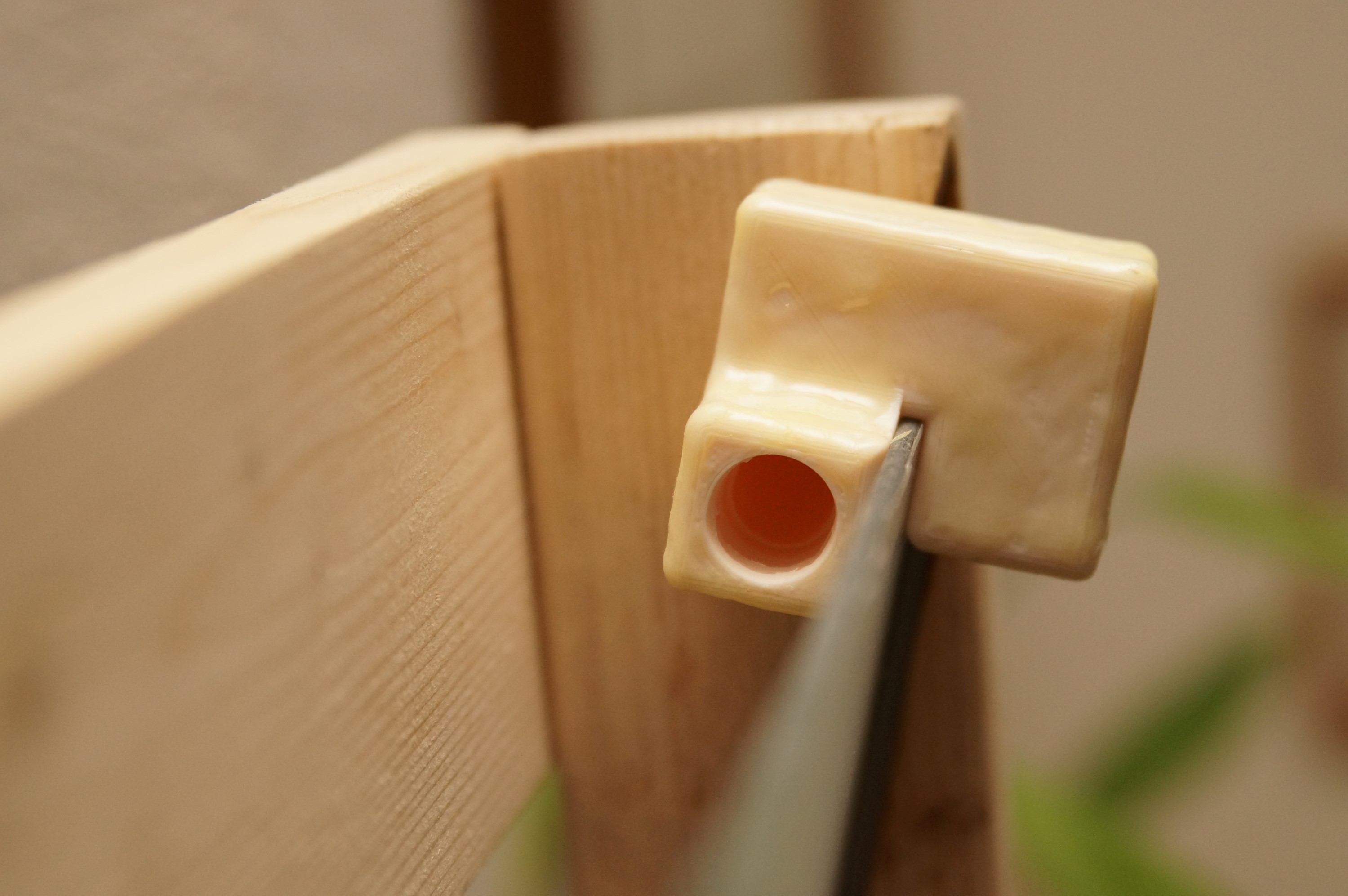
This part is designed to accept 5/8" outer diameter clear vinyl tubing in each port via compression fitting. The part is made to sit snugly on the top edge of the glass. Water comes up in the back and is redirected over the glass edge and out a side port on the other side.
To mitigate potential leaking, I sealed the exterior of the part with a plastic epoxy. The .stl files can be found at http://www.thingiverse.com/thing:329725 and brief video highlights of the print (which can help visualize the internal construction) are uploaded at http://youtu.be/7OoFe0CkZio. Here is a picture of the end result:
Waterfall Wall with LED Illumination
A translucent wall with custom shelves, a waterfall feature, and remotely-controllable lighting
 infinityis