 Michael Frank Taylor
-
Reflections
05/21/2017 at 20:12 • 0 commentsAs forecast in my previous log, I have reluctantly decided to abandon the current design as I have spent a disproportionate amount of time attempting to resolve the problems without recourse to modifying the PCB layout (not in itself a problem) and having the new PCBs assembled (which is a problem on account of cost). I have now decided to concentrate on a modular design that will, if successful, be easier to prototype, use cheaper components and be much simpler to assemble with simple tools.
Meanwhile I've added two more Raised Beds but am still struggling with manual watering pending completion oh the automatic system! We'll get there eventually
-
Major revision required!
03/30/2017 at 21:57 • 0 commentsRegretfully this Project has run into problems and solutions have yet to be found. Despite having has some PCBs professionally assembled, testing has been problematic with unreliable results that almost certainly are attributable to shortcomings with the board layout and particularly with insufficient attention to decoupling of the ESP8266 supply. Also for reasons unknown there is a wide variation in the current drawn from the supply by individual units. Currently I'm trying to decide whether to redesign the PCB layout to accommodate improved supply decoupling (this would mean the expense of fabricating and assembling the boards) or whether to completely start again and build using commercially available components, namely The Adafruit Solar Charge Controller, a Huzzah ESP8266 module together with standard Boost Converter and H Bridge Driver sub-modules. The larger Waterproof Box required would facilitate the use of a more powerful Solar Panel as it has been ascertained that the existing panel is insufficient to keep the battery cell charged. I still have one or two things to try before deciding but it looks increasingly likely that a new solution that will not involve attempting 'hot plate soldering ' of QFN components or awaiting deliveries from China is preferred.
-
Inadequate Power Supply
02/12/2017 at 21:03 • 0 comments![]()
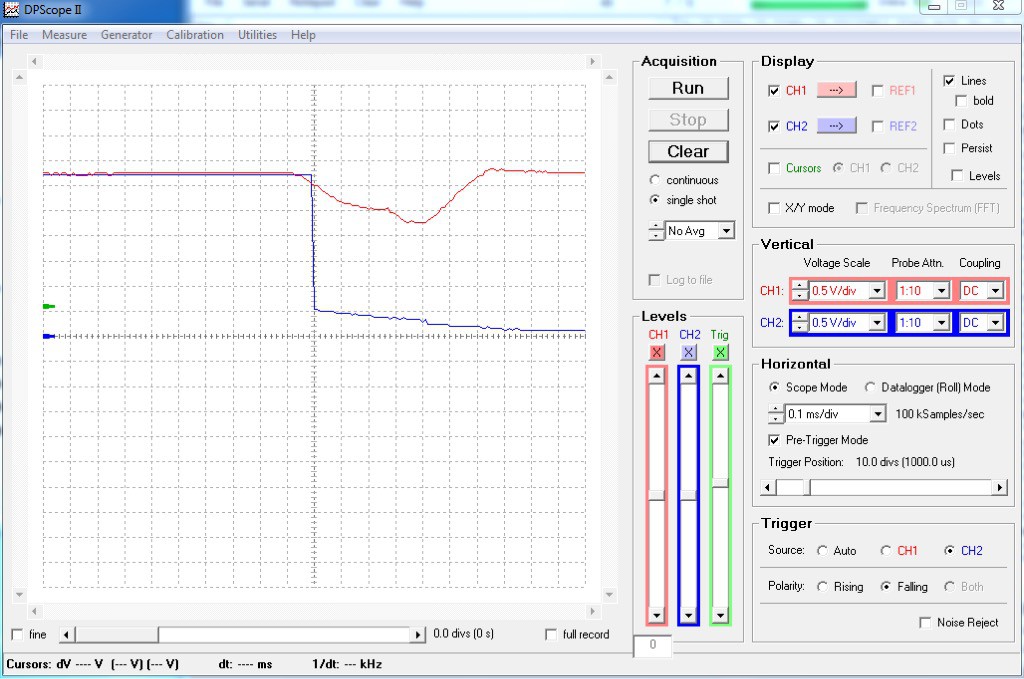
Those of you who are following this Project will know from my last log that I have been plagued by intermittent resets whilst loading firmware and testing the pcb. I have at last managed to trace the cause and capture the offending waveforms on my digital 'scope. The design uses an LDO to provide the 3.3V required by the ESP8266. The particular LDO used TPS77733 monitors the regulated voltage and provides a signal should it drop by 5% . This signal can be used either as a 'power low' or as a Reset'. Unfortunately I chose the latter. Consequently whenever the ESP8266 draws heavily on the regulated supply, for for example during wireless setup or firmware loading, then the PCB resets.
The screen capture above shows the 3.3V (red trace) and the reset line (blue trace). The Input Voltage tothe LDO (Vcc) comes from the GPIO pins of a Raspberry Pi, Nonimally 6V at 600 mA but obviously inadequate. I now await delivery of a stabilised Laboratory PSU to continue testing. Hopefully these problems won't recur when powering from the a solar panel with a fully charged backup battery.
-
A frustrating problem - solved
02/05/2017 at 20:49 • 0 commentsTesting of the boards looked to be going well until the stage of flashing the firmware was attempted when, in spite of careful attention to the state of the input pins of the ESP8266 device, it was relactant to enter 'boot mode' on application -of power. As is often the case with such problems the cause was not simplistic but a combination of design errors compounded by a faulty (fake) chip in the external FTDI USB to TTL converter being used to load the firmware.
Fortunately only component value changes are necessary on the board itself to correct the design shortcomings and the firmware has now been successfully loaded and testing can proceed. Now that the initial loading of firmware has been achieved it is hoped that future changes can be covered by Over the Air (OTA) capability that facilitates changing and uploading the code 'wirelessly '.
-
Got a few problems
01/26/2017 at 23:05 • 2 commentsSeems that I underestimated the problems that would result from attempting to assemble the PCB without the benefits of a reflow oven and a pick and place machine. After several attempts using a hot plate I have had to concede defeat as the QFN device (MCP73871) proved impossible to position and solder with the crude equipment at my disposal. Lessons learnt are to ensure that you have a good quality stainless steel stencil, preferably with a jig, and a reliable controlling the heat setting whilst monitoring the temperature of the hot plate.
So I admitted defeat and had half a dozen boards assembled professionally.
Testing is now underway but it seems that there is a problem that prevents uploading of the firmware. I have had much experience with ESP8266 devices although this is the first time I've used the -F version. Believe me, I am aware of most of the pitfalls to be avoided when setting up the correct conditions for 'boot mode' but currently, in spite of my best efforts, the devices fail to yield their MAC addresses which leads me to believe that the system has not defaulted to the correct mode on power-up. Thankfully I have a, cheap and cheerful, digital oscilloscope that should help get to the source of the problem.
Hopefully a solution will be found soon as the gardening season is rapidly approaching and there is much to do before I can deploy the system.
-
Populating the bare board
11/06/2016 at 16:39 • 0 comments![]()
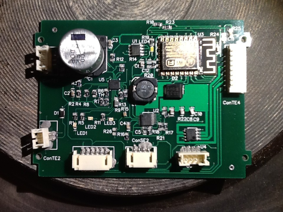
Armed with a cheap stencil, solder paste, tweezers, hot plate and packets of small SMD components the time had come to take the plunge and 'hot plate solder' the bare board to be able to finally test the design before committing to having a batch of PCBs professionally assembled. The result is shown in the attached image, pasted but only slightly heated.hence not yet reflowed. So all looks good however the eagle-eyed amongst you may have noticed that one or two components, critically U1, U2 and U4 are, slightly misaligned. Durin my efforts to correct this by reheating the board and nudging them into position, I accidently dropped the Assembly with disastrous consequences. Ah well, you can't win every time so if at first you don't suceeed then try again and maybe again,
-
Oops! correcting the errors
10/22/2016 at 21:52 • 0 commentsUnfortunately having had the new layout fabricated I carried out some further checks on the layout which revealed a couple of errors that, whilst not rendering the boards completely unusable, will require changes to the firmware that I had hoped to employ. The errors are being corrected for the follow up PCBs that, once finally proved are to be professionally assembled. My 'hotplate' endeavours, whilst good enough for prototype testing do not satisfy my aims of consistent quality and a repeatable product.
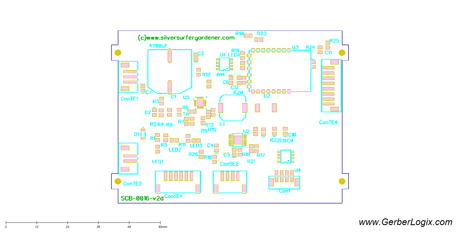
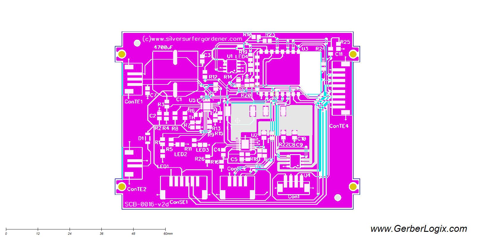
The Gerber files will eventually be available on Github but to give a 'taster' of the design I am attaching two images, courtesy of a 3rd party Gerber Viewer. Highly recommended as a check that your chosen fabricator has got a correct interpretation of the files. I've only shown two views but all layers can be viewed individually or collectively.
![]()
![]()
-
Link to rushed youtube video
10/03/2016 at 21:17 • 0 commentsNot a very good effort and it will need much updating but just to say there is a video on you tube showing a few details -
The Final Steps
10/02/2016 at 20:00 • 0 commentsWork is progressing steadily and today I am creating the Bill of Materials (BOM) for the modified PCB after which, assuming all works as expected, the final assembly will be carried out during which I intend creating a video showing all the steps necessary for construction of the final Unit. For this purpose I have already purchased a couple of the 'Solar Powered Garden Lights' that provide the core features of Solar Panel, Battery and Waterproof Housing that are essential for this Project. These units are available from Amazon or possibly directly from the Manufacturer. Gerbers for the PCB will be put on GitHub in due course together with links to firmware when the latter has finally been proven.
I hope to add a short video before the deadline for this Stage. As I'm in the GMT Zone and the Organisers are in the PDT time zone then I might just have sufficient daylight tomorrow morning for my iPad to earn its keep! Watch this space.
-
A step nearer
09/26/2016 at 17:19 • 0 commentsOnce again the summer months have flown by and the vegetables and other plants in my Raised Beds have suffered from a lack of regular watering. I now have the Autumn and Winter months to complete my irrigation Project if next season is to be more successful.
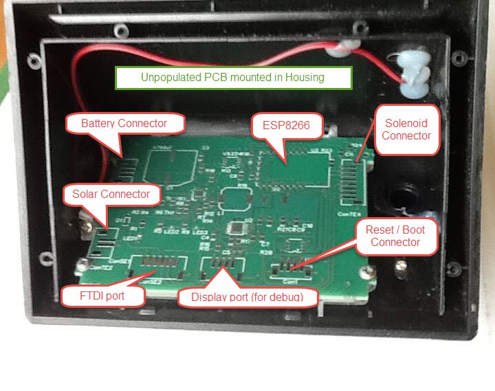
However, progress has been made on the design of the PCB and prototypes have been manufactured although they have yet to be populated with components and tested. Completing the layout and preparing the gerber files took considerably longer than anticipated and, as yet, there is no guarantee that this is error free! So it's back to the 'hot-plate' soldering before the board can be proved.
![]() The firmware fis another aspect of the work still in progress. Programming is not my strong suite so I was very relieved to find a Project on GitHub that looks very promising ad even provides pre-compiled binaries for flashing to the ESP8266-12E. Although it would be too much to expect that it will fulfil the Requirement without any modification it will certainly form, with Node-Red and the other supported features a good basis for the Project. My PCB is an adaptation of the board designed for the Home Automation Project that is fully documented on the http://tech.scargill.net blog pages that are the work of Peter Scargill and Adian Ruff .
The firmware fis another aspect of the work still in progress. Programming is not my strong suite so I was very relieved to find a Project on GitHub that looks very promising ad even provides pre-compiled binaries for flashing to the ESP8266-12E. Although it would be too much to expect that it will fulfil the Requirement without any modification it will certainly form, with Node-Red and the other supported features a good basis for the Project. My PCB is an adaptation of the board designed for the Home Automation Project that is fully documented on the http://tech.scargill.net blog pages that are the work of Peter Scargill and Adian Ruff .Work outside has continued and I now have the irrigation piping in place (buried) and two of the Solenoids mounted adjacent to their respective Raised Beds. Now, before the Winter sets in I need to clear the ground of this year's 'failures' ready for a new season in 2017 with automated solar powered irrigation.
Solar Powered Garden Irrigation System
Minimal effort Solar powered wireless controlled automatic watering
 The firmware fis another aspect of the work still in progress. Programming is not my strong suite so I was very relieved to find a Project on GitHub that looks very promising ad even provides pre-compiled binaries for flashing to the ESP8266-12E. Although it would be too much to expect that it will fulfil the Requirement without any modification it will certainly form, with Node-Red and the other supported features a good basis for the Project. My PCB is an adaptation of the board designed for the Home Automation Project that is fully documented on the