-
Internal Clock x Temperature
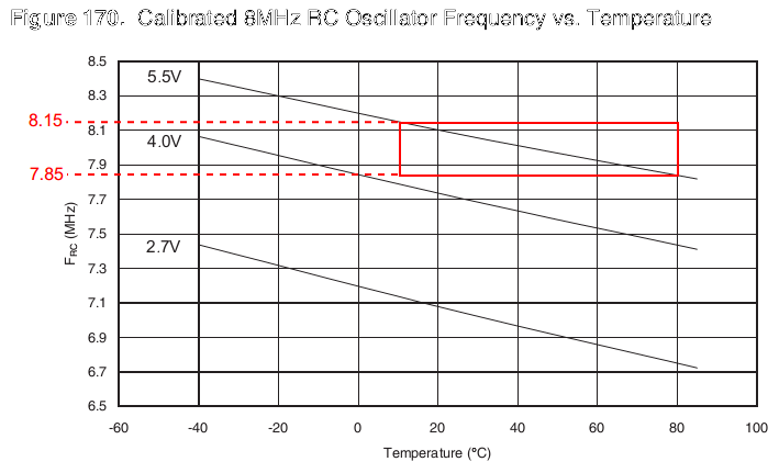
04/14/2016 at 21:57 • 0 commentsInitially the internal calibrated RC oscillator was considered to be the main clock source for the circuit but according with the datasheet the frequency variation with the temperature is too high, specially on the operation range foreseen for the device which will be installed on the engine bay.
![]()
With the internal oscillator is out of game the solution is to use a crystal. The frequency chosen for the crystal is 16.0MHz because it is the same used in Arduino thus allowing me to prototype the circuit as a shield.
-
The First Subject
04/13/2016 at 21:52 • 0 commentsThe first subject for this project is a Gurgel X11 manufactured in 1976 by Gurgel Motores do Brasil, equipped with a 1300cc air cooled VW engine (BJ series). Its current ignition system is a Hall Distributor but the advance curves both centrifugal and vacuum are not good as the advance rises too soon and too much.
![]()
-
Pin Assignment
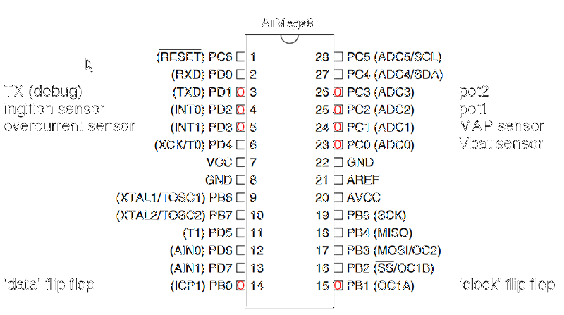
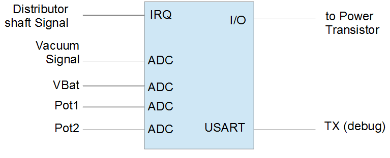
04/13/2016 at 20:37 • 0 commentsAfter the considerations about the hardware and software architecture the pin assignment was defined
![]()
-
Choosing a microcontroller for the project (2)
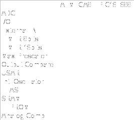
04/12/2016 at 21:01 • 0 commentsAfter comparing some characteristics of the chips, I've decided to stay with the AVR because of the output compare modules, which are convenient for this use but are not present on the PIC.
![]()
Also the PIC prescaler for the 16bit module might not be enough for the 8Mhz clock.
-
Choosing a microcontroller for the project
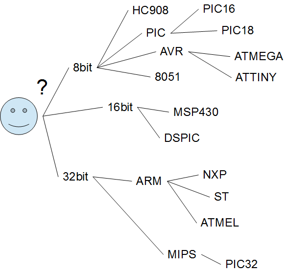
04/12/2016 at 01:37 • 0 commentsChoosing a microcontroller for a project is a very tough decision. If you look for discussions about this matter you will find hundredths of pages with discussions, debates, argues, all of them with valid arguments claiming microprocessor x is better and yet none of them give enough substance to decide what's better.
![]()
I'll be more pragmatic and will start with the parts I have more quantities in my bins:
- PIC16F688
- ATMEGA8
Then I'll check if they meet the requirements for this project:
- One external IRQ for the signal from distributor (points, hall sensor, etc)
- One I/O for driving the power transistor
- Two ADCs, one for the battery voltage and another for the Vaccum signal
Optionally:
- Two ADCs for potentiometer inputs (for tuning charge time and base delay)
- One USART for sending debug messages
![]()
Both will do!!
I'll need to get deeper into the project details before I decide.
Guri: Ignition Controller for Air Cooled Engines
Ignition controller for VW air cooled engines.
 danjovic