Karl S
-
Some more (less-important) changes, and an update
06/07/2016 at 03:04 • 0 commentsThe good news is I'm basically done with the schematics. I've got a bit more still, but nothing particularly major. I hope to get them up on GitHub by the end of the week.
The other good news is that I was looking at displays and decided my best option was a 2.2" graphic display from AliExpress, so that means it can have a very basic scope (or at least graph against time).
The not so good news is that seeing I've got the design pretty much done, I decided to check out the price I was looking at – and it was somewhat higher than I liked. So I've cut down on a few bits and pieces, but fortunately that doesn't significantly affect the usefulness of the design. And I'm happy with the price after doing it too.
So I'll remove / replace the following (with more details for each afterwards).
- A separate 16-bit ADC is too expensive for my personal budget requirements, so has been dropped. Probably means a resolution of 13 bits (4000 count).
- The resistance reference has been replaced with a cheaper but less accurate option.
- The rotary switch will be replaced with one or two more touch-switches, and a push-button switch.
The micro I'm going to use (STM32F373) has an integrated 16-bit ADC (three, actually!), however it has an integral non-linearity of 14 LSB (effective number of bits is about 12.3). So I'm planning on using that, and only counting on using 13 out of 16 bits (for a maximum count of 4000). I will also use calibration if that is possible – a constant-current changing a capacitance will give me a nice voltage ramp to check against, and if it is feasible to use the data gathered I will increase the number of bits appropriately. But the nice thing is that it is a Sigma-Delta ADC, so the anti-aliasing filter can probably just be a simple first-order filter. I will try to leave enough IOs available (broken out internally) that it should be easy to incorporate a better ADC without modifying the design.
I don't need extremely accurate resistance measurement, but it does mean I won't be able to use resistance measurement to get accurate voltage division ratios. That's not a problem though. Not even a software change here!
The rotary switch isn't particularly expensive, but I can still save a bit by replacing it. Besides, auto power-off and a rotary switch with an off position doesn't make sense to me. A push-button switch is used because touch-switches can't wake up the micro from standby. The good thing is this means the user-interface can be much more versatile.
I have also replaced the high-current range with a second low-current range for even lower currents for what I build. This lets me replace a relatively expensive fuse with a much cheaper one. But anyone could easily use a different fuse and current sense resistor to have a high-current range.
And something I would like some advice on: with things like resistors and capacitors, I can often choose what package I want (e.g. 0603 or 0805) and obviously I'd standardise that, but sometimes only one is available (at least at that price) or I already have that component on hand with a particular package (which I'd obviously want to use). I'm hesitant to use a mix, because if anyone else ever wanted to build it (not likely, I know, but I'd like to do this right) they'd either have to modify the design for their parts or put up with my mess. The idea I've got right now is to use a compound footprint that accepts both 0603 and 0805, and possibly more sizes if relevant (e.g. I have some 1206 100k and 1210 10k resistors that I'll probably use somewhere), and use that making it possible to use the exact same PCB with various different component packages. Your thoughts? -
Slight specifications change
05/07/2016 at 01:39 • 0 commentsI've been doing a bit more work on various stuff, and have decided to drop the rated voltage. A 600 V rating means 600 V RMS – about 850 V peak for a sine wave. The issue is that certain components in the input (e.g. fuses, low-impedance connection relays) need to be able to handle the full voltage, and ones that can handle that voltage are quite expensive as a fraction of the total. So I'm dropping to a 300 V rating (about 425 V peak), which means I can use components with lower voltage ratings which are much cheaper.
-
Connections interface again...
04/19/2016 at 09:46 • 0 commentsSo yesterday I was working on the schematic (in KiCad) for the main connections, and came across a few important difficulties that hadn't come up earlier when I was doing a rough sketch on paper. The thing was, earlier on I'd just said "the voltage needs clamping, but that's easily done with some diodes – worry about details later". When I was actually doing the schematics, I suddenly had to think about those details. And the voltage measurement interface that I'd thought was pretty easy is suddenly much harder.
The first detail is that if the input simply comes through 10 M ohm as I was planning, then small signals have such a small current available that leakage and bias currents become a major problem.
The second detail is that diodes don't make good clamps. When the current is low (e.g. a small voltage across a large resistance), the voltage drop is also low. I had previously looked at some diode data sheets, and decided that there seemed to be an asymptote at about 0.5 V that was being approached – instead I should have read up on some basic diode theory, where at low enough currents (low enough that the resistance doesn't show much affect, so often several tens of milliamps) the diode forward voltage has an exponential relationship to the diode current. Great, that won't work, and especially not when you consider the above problem...
So I'm going for a two-part solution (if it works, and unless I come up with something else): voltages less than 1.5 V go through the resistance circuit so that they've got a low input impedance (but they go straight into an op-amp buffer, so the actual input impedance is actually significantly higher than 10 M – the low actual resistance only matters when the voltage clamping comes into affect); and using low-leakage MOSFETs triggered by comparators for clamping.
The biggest issue I can see at a glance is that I can't use the voltage measurement in the resistance circuit when actually measuring resistances, since it would be measuring the current instead. Better would be to put it in its own circuit, but that would mean a second high-voltage solid-state relay, and they're not exactly cheap...
-
Accuracy
04/14/2016 at 00:19 • 6 commentsI'm thinking there are basically two ways to obtain good accuracy in something like a multimeter: use accurate components and such, or use less accurate components and then calibrate the meter. I intend to use a hybrid approach: a couple of accurate components, to allow me to use the meter to calibrate itself – not by comparing to itself (which obviously doesn't work), but by measuring the less-accurate components.
Obviously the values of the less-accurate components won't change. But the scale factor they produce, whether as part of the voltage divider for voltage measurement, or the current shunts for current measurement, will – and that can be accounted for in software. No, I'm not handing a hardware problem over to software; I'm saying the software would have to handle it anyway, so the compiler may as well compute the constants from actual component values instead of me calculating the constants from the selected component values.
First, an accurate voltage divider will be very important, and is easy to make. Just measure the voltage across each resistor, and you can easily calculate the exact division ratio – the voltage measurement doesn't need to be accurate either (the ADC reading is good enough), but resolution helps. Make sure the resistors are of similar values to minimise ADC gain error.
Most of all we need accurate voltage measurement. This requires an accurate voltage reference, which I will buy. The complication is that the ADC will have gain error, which must be calibrated out. I should be able to do that by using an accurate voltage divider to measure an accurate fraction of the reference, which gives me both what the ADC actually reports, and what it should report. I can't just measure the reference directly, because the particular ADC I'm using usually reads high.
I also need to be able to measure resistances accurately, primarily for the current shunts and also for actual use – and it is probably the easiest way of getting accurate voltage dividers too. The best way to do this will be to buy one accurate resistor and use it in an accurate voltage divider – we can then easily calculate the accurate value of other resisters.
I will still need low temperature coefficient resistors, but I won't need tight tolerances for most of them.
So one accurate voltage reference and one accurate resistor (I'm looking at parts with 0.01% tolerances and temperature coefficients of about 10 ppm/K – after all, I'm going to end out with an accuracy lower than whatever theirs is, hence my aim of 0.1% or better overall), and I should have good accuracy on every range of every measurement type.
-
External design
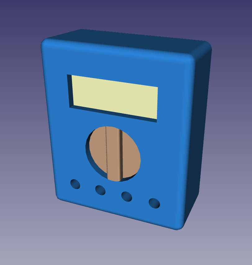
04/13/2016 at 01:53 • 2 commentsI intend to have a fairly traditional multimeter external design, but with a few changes:
![]()
For a start, I don't have access to custom LCD screens like commercial ones do, so I can't do that. I do still want to have multiple pieces of information displayed at once, so that eliminates a 7-segment display. I will probably go for an alphanumeric display, although a graphic display may actually be better (that way I can have varying text sizes and such) – I'll look into it further when I get to that stage. The alphanumeric display gives a minimum width, and unfortunately it is wider than I'd like (especially when I allow as much room around it as I did – that concept render is 120 mm high and 100 mm wide).
I'll stick with a mechanical rotary switch for the main function switching. I'm not sure whether it'll be something I buy, or whether it'll be some tracks on the PCB as in most if not all commercial multimeters.
For any buttons, they'll be above the rotary switch, on either side of it. I'm currently thinking of capacitive touch sensing, with a dip or ridge in the case to show their location.
For my prototype I'll make the case out of wood. What I'd really like is aluminium with a suitable insulating layer inside, but I don't think I can manage that (I could mill it out of a solid block, but that would be extremely wasteful and also expensive). But whatever it is, in addition to looking OK it needs to be reasonably strong (both for if it gets dropped, and if a fuse blows with a very high current) and have the outside well insulated from the circuit.
-
Features...
04/12/2016 at 06:58 • 0 commentsHere's some features I'm planning on:
- Auto-ranging
- True RMS
- Very fast response times
- 16-bit resolution (30,000 count) at 50 k samples / second (16.7 k / second if multiple channels are being measured), and 12-bit resolution (2000 count) at 1 M samples / second (using the ADCs in a STM3F373)
- Data logging (probably via USB)
- Signal generator (may be USB-only, or whatever other means logging uses)
- Power measurement (measuring both current and voltage at once)
- LCR meter
- Li-Poly battery
- Any extra GPIO lines on the micro will be broken out – probably enough for a very basic logic analyser
I'm also aiming for better than 0.1% accuracy (more details about how I expect to achieve this another day...), but if I can only get 1% that'll be OK. This (0.1%) is 30 times less than the resolution (0.003%), but the extra resolution is still useful (and reduces any errors from the analog-to-digital conversion). By way of comparison, cheap multimeters (I have three particular models in mind) may have an accuracy of 0.5% to 1.5%, while having a resolution of 4,000 or 0.025%, to give a resolution 20 (for 0.5% accuracy) or 60 (for 1.5% accuracy) times higher than the accuracy.
Of course, all the normal features will be present as well (current, resistance, continuity, diode test, frequency, duty cycle...).
-
First task: connections interface design overview
04/11/2016 at 00:18 • 0 commentsMy first task is to figure out how the connections can safely interface with the microcontroller. Why first? Because if I can't get this working, I can't go any further.
All the standard functions are needed, and possibly one or two more. So I've got to be able to measure current, voltage, and resistance. Each has its own challenges, but I think I've worked them all out. What makes it difficult is that any combination of terminals must behave itself if presented with the full rated voltage (in this case 600 V because I'm aiming for compliance with CAT III 600 V, and this is one feature the standards require).
Current:
It is normal for current measurement to have dedicated terminals, probably because relay contacts can have too much resistance (e.g. 0.1 ohm). I'll go this route too. The voltage isn't going to be a problem because we're just measuring across a very small resistor. And if it is, some diodes can clamp it – they'll just make the fuse blow faster, because it definitely was going to anyway.Voltage:
Basically a voltage divider with suitably high resistance. The only detail is switching the resistors in and out (for auto-ranging), but an analog switch / multiplexer can do that OK (its resistance must be accounted for though, so I'm going to look at using MOSFETs instead). Once again, some diodes can easily clamp the voltage within range. And there is no need for a fuse, because any current they draw is coming through about 10 megohms. But still use some MOVs or similar to suppress transients.Resistance:
This is the one where I've had the most problems. It has to be relatively low resistance because we need to provide an output of around a milliamp with a reasonable voltage left for diode measurements (in other words, about 2k to allow 1 mA into a load with a 1 V drop]). But it still has to cope with 600 V on its input without passing that on to the micro. Clamping doesn't work on its own, because that would be a power dissipation of at least 180 W. But it can be disconnected immediately if the voltage exceeds the limit. I intend to use a solid state relay for this. The clamping will prevent a high voltage being applied to the micro for the millisecond or so that it takes to turn off.
Open Source Multimeter
A relatively low-cost but full-featured and safe multimeter.