Close
0%
0%

Tiny Wireless Capsule Camera

A tiny wireless capsule camera for medical imaging or space-constrained environments

Similar projects worth following
Tiny, pill-sized cameras are frequently used in the medical field to visualize the gastrointestinal tract, particularly areas not readily accessible by bulkier devices. Increasingly, consideration is given to using these devices in patients who cannot tolerate, or are otherwise unwilling to undergo, a conventional colonoscopy. The possibility of displacing or augmenting these methods with tiny, non-invasive devices is very exciting.

Unfortunately, pill cameras can be very expensive, costing hundreds of dollars for what is effectively (sure, just wash it off!) a one-time-use device. These devices also inevitably involve closed-source hardware/software and sophisticated manufacturing not available to the average person.

The challenge of this project is to build and prototype an open single-camera pill-sized capsule camera usable for medical applications. The design will also be sufficiently modular and adaptable to accommodate other space-constrained applications.

Tiny Wireless Capsule Camera

A capsule endoscope, also known as a capsule camera, is a tiny camera that can be safely swallowed and passed through the digestive tract. The device uses one or more camera sensors to capture images of the gastrointestinal tract and is useful in diagnosing or evaluating a myriad of diseases or dysfunctions of the digestive system. Many configurations are possible, but the core functions boil down to (1) capture images, (2) process and either store/transmit the image, and (3) operate continuously for 24-48 hours.

This kind of device is especially convenient for evaluating hard-to-reach places (such as the distal small intestine). It is also useful in situations where the patient cannot (or refuses to) tolerate more conventional approaches such as colonoscopy or esophagogastroduodenoscopy (EGD a.k.a. upper GI endoscopy). Though capsule cameras have not supplanted these conventional, "Gold-Standard" methods, they nevertheless have become an invaluable medical tool.

Why do this project?

Short version: I think it would be fun to build one.

Long version: Around the hospital, I have occasionally had the privilege of seeing these devices in action. The branded, FDA-approved versions used in real human patients are incredibly sophisticated systems with years of research and safety testing behind them. Like most things in medicine, they are also incredibly expensive and, understandably, highly proprietary. Devices like these take millions of dollars to develop and years (even decades) of research and development before they even see human trials, let alone actual sales. Overall, it's pretty inaccessible technology.

Still, the proliferation of tiny, versatile cameras in phones, tablets, and elsewhere made me wonder if it would be possible to develop a capsule camera with off-the-shelf parts and open software, and build it with materials, manufacturing, and resources readily available to the amateur hacker.

Crazy? A mini 2MP camera module in a 8mm x 8mm package can be bought on eBay for <$5. Incredibly powerful 32-bit micros have become completely accessible to total novices. A 4-layer board with 5mil pitch can be had for $10 per square inch (of note, I estimate the total board area needed for this project to be barely 1 sq inch. Even relatively cheap 3D printers may be able to make a suitable enclosure. This is hardly crazy (ok, maybe a little).

Application Example:
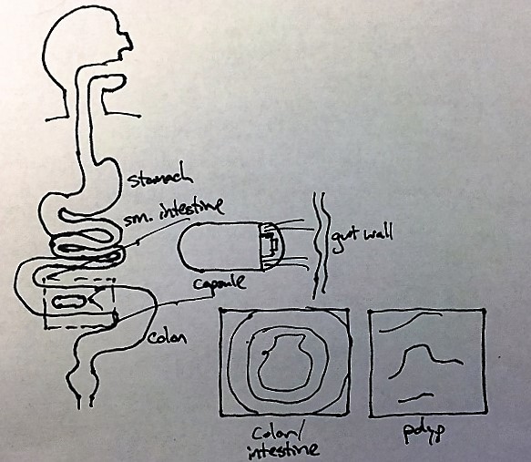
Full disclosure: I do not at this time have plans to ultimately test this device on living (human or otherwise) subjects. That particular ethical and legal minefield is not something to shoot for at this time.


Top-Level requirements

The system I want to build must meet a handful of high-level requirements.

  1. Single camera VGA or better resolution (2MP goal) imaging captured at least every 10 seconds
  2. On-board storage of at least 15 minutes of images
  3. Wireless transmission of image data to external storage device
  4. 24-hour battery life
  5. 15mm diameter x 30mm length maximum (smaller better)

System Design

Overall System
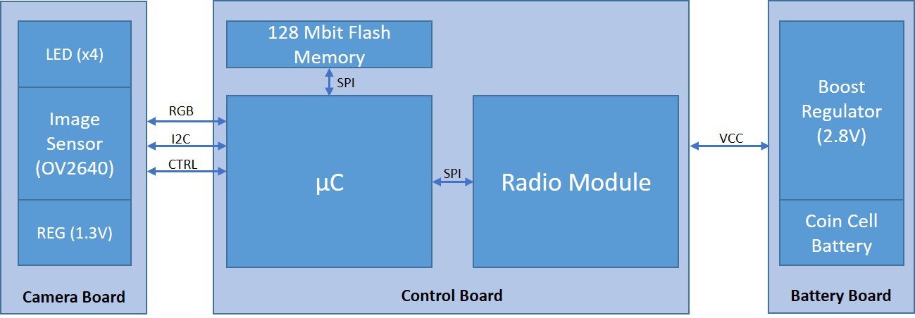
The capsule hardware consists of three separate boards/modules:

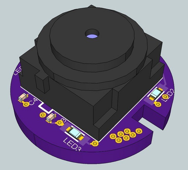
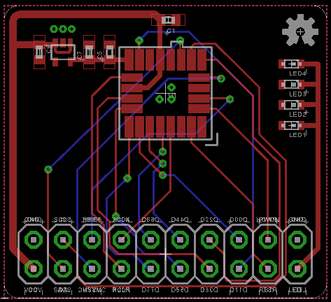
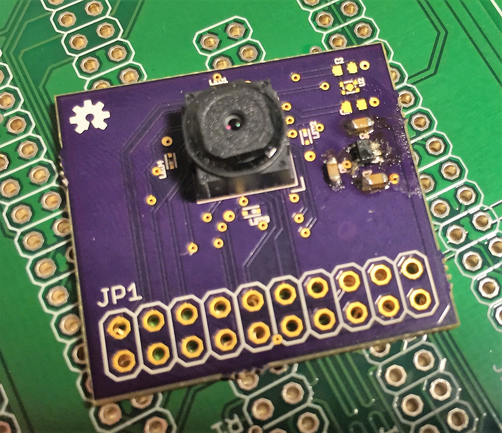
Camera: contains the image sensor, LED flash, and supplemental power regulation required by the image sensor.

Battery: contains the battery holder, magnetic reed switch for power on/off, and the main boost regulator.

Control: contains the processor, storage memory, and radio transceiver.

Camera
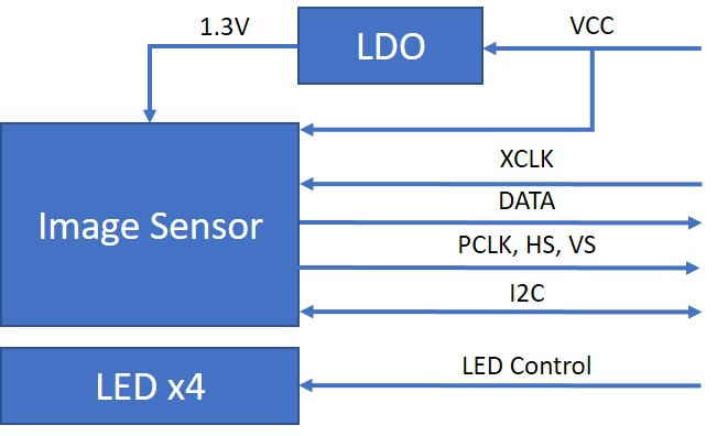
The camera board contains the OV2640 camera module, a (up to) 2.0 megapixel image sensor with parallel RGB outputs. The image sensor requires a 2.8V rail for digital and logic, and a 1.3V rail for analog power (provided by a small LDO regulator). Since the typical application lacks ambient light, there are 4 white LEDs to provide a 'flash'.

The OV2640 accepts a minimum pixel clock of 6MHz (nominal 24MHz), provided by the system processor. The camera data electrical interface is 8-bit parallel, configurable as YUV, RGB, or RAW. The datasheet also mentions JPEG compression as an option, though this does not seem well-documented....

Read more »

  • 1 × OV2640 2.0 Megapixel CMOS image sensor
  • 1 × nRF24L01+ 2.4 GHz Wireless Transceiver
  • 1 × STM32F411CE ARM Cortex M4 MCU
  • 1 × S25FL128SAGNFI001 Memory ICs / FLASH Memory
  • 1 × CT05-1535-J1 Electronic Components / Misc. Electronic Components

View all 9 components

  • Image capture

    Ryan Bailey02/07/2017 at 22:43 0 comments

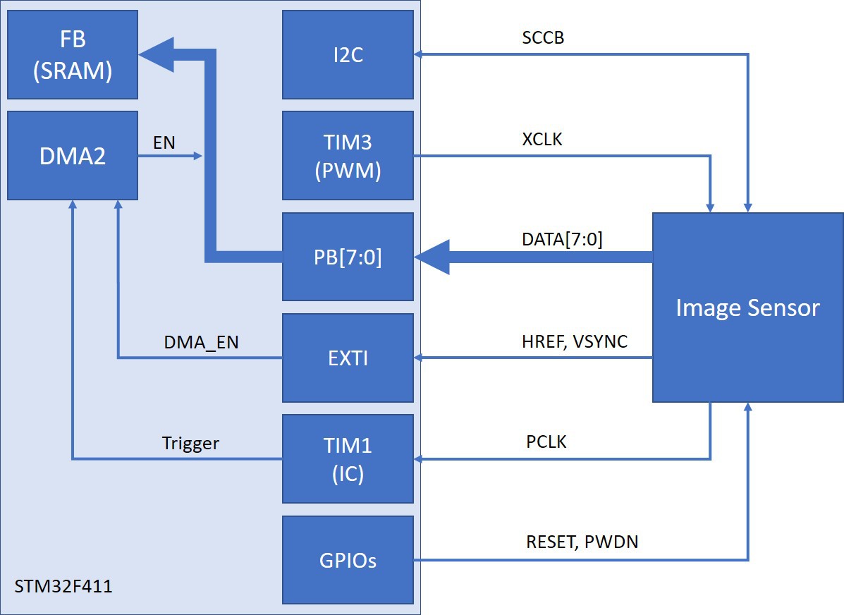
    One of the bigger challenges recently has been devising a way to capture output from the camera efficiently without relying on the DCMI interface available in other STM32 devices. One of my goals from the beginning was to avoid resorting to BGA or extremely fine-pitch parts. The idea was to keep board design and manufacturing relatively simple and cheap. Unfortunately, I have not found a DCMI-capable part with a sub-10mm diameter in a non-BGA package.

    It is tempting to switch to something like the F407 or F429 (as found in the OpenMV). For now, I plan to forge ahead with the following strategy:

    Image Capture Block Diagram

    Much credit is due to the following article (link) that outlines how to capture data using DMA triggered by a timer in input capture mode. ST also has a decent app note (AN4666) discussing general-purpose synchronous parallel data transfer that proved fairly helpful.

    Full image capture should be available soon - there are still some kinks to work out with camera configuration.

  • State of the Project: Part 2

    Ryan Bailey10/10/2016 at 03:39 0 comments

    It's been a good while since I've posted updates here. Several posts made earlier are more or less back-logs from the last three months, most of which I've been traveling to meet requirements for the rest of my education. Things are moving ahead and I have prepared a small video overview below:

    Updates by specific system:

    1. Camera: Progressing. Further tests needed once updated proto boards are assembled.

    2. Power: Finished

    3. Main Board: Updating Layout

    4. Communications: RPi receiver implemented, command interface and display of received images in progress

    5. Enclosure: Test enclosures working. Likely re-design pending new dimensions of board layout updates (see above).

    6. Code: Test board and programmer working. Further coding efforts pending.

  • Camera footprint correction

    Ryan Bailey10/10/2016 at 03:20 0 comments

    I usually do my best to check (and re-check) footprints before things go out to fab. Unfortunately, there was an error in the camera module footprint that shorted one of the power supply pins to ground. I think I had visually transposed a few things from the (minimal) datasheet on this device. Luckily, the fix was relatively easy and some replacement prototyping boards were sent to fab.

    The replacement camera modules arrived just after I had left for two months on the road. I intend to find some time in the coming weeks to assemble them - especially now that I have a viable strategy for keeping the module housings from melting during reflow

    Stay tuned.

  • Layout Update

    Ryan Bailey10/10/2016 at 02:51 0 comments

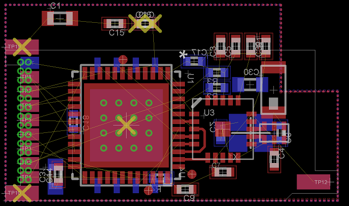
    I spent some time during my travels going over the original layout. I've decided to take another crack at slimming everything down further - this means a main board width of 10mm or less. It's also a good opportunity, based on some previous dummy board assembly, to get the board-to-board approach right. I'm particularly interested in how far I can push down the size of castellations.

    Obviously, still a work in progress. The goal is still to get everything on the same board using 0402 passives and OSHPark 4-layer spec DRCs. You can see why a lot of commercial units use flex circuits extensively.

  • Receiver Setup

    Ryan Bailey10/10/2016 at 02:38 0 comments

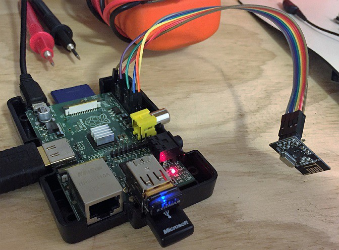
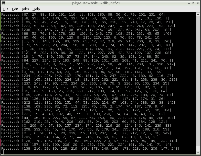
    Radio update: configuration and sensor data will be received by an external device, in this case a Raspberry pi with a nrf24L01+ module attached.

    Right now I'm simulating 16-byte image packets sent from the capsule camera to the RPi.

    Next steps include implementing full back-and-forth communication and displaying received image data on the RPi.

  • Microcontroller board update

    Ryan Bailey07/15/2016 at 03:26 1 comment

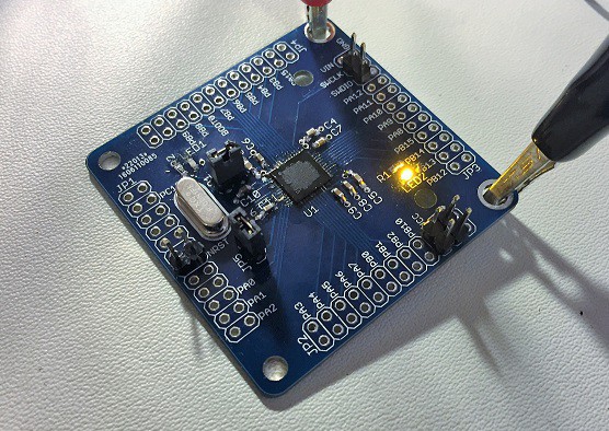
    Update: Initial programming was a modest success. There is still some temperamental behavior to work out with the programmer - some searching suggests that termination/reflection issues on the data line sometime cause programming to fail. Still, I was able to load and run a simple LED blink program:

    It's been a busy couple weeks but I finally found the time (and the correct parts) to finish assembling a couple of the microcontroller testing boards that I cooked up last month.

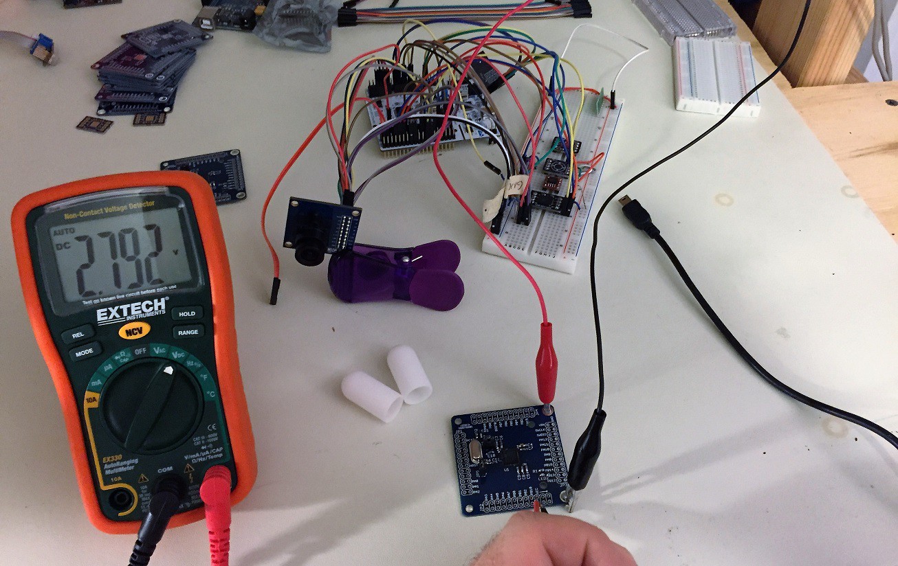
    Also pictured: complete mess-of-wires version of the final system. The main voltage rail is 2.8V, regulated from 4-5V input, as required by the camera.

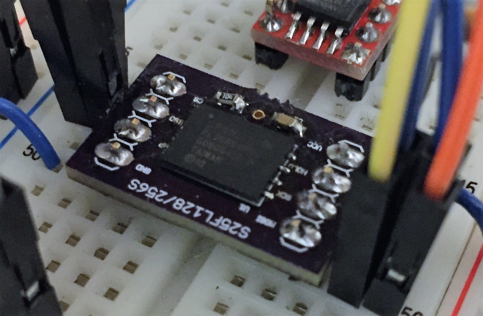
    Also notable is the quick proto board I threw together for the 256Mbit flash device. It's a slightly weird-looking package so I wanted to try a standalone board before 100% committing it to the final design.

    No magic smoke so far. Programming tests coming soon.

  • A quick update

    Ryan Bailey07/01/2016 at 15:56 0 comments

    It's been a busy couple weeks with the school year ending. Subsystem software prototyping is almost finished. Most of what I've accomplished so far has been under the mbed environment, but sometime in the coming week or so I'll be ready to start transitioning over to writing specifically for the STM32F411 micro. Speaking of the F411, the proto boards are back and assembly will start sometime today:

    Also of note, I had a handful of dummy enclosures 3D printed through the Dirty SLA service over at dangerousprototypes (http://dangerousprototypes.com/store/print3d) just to get my head around the case size and any issues with the board fit (so far so good!).

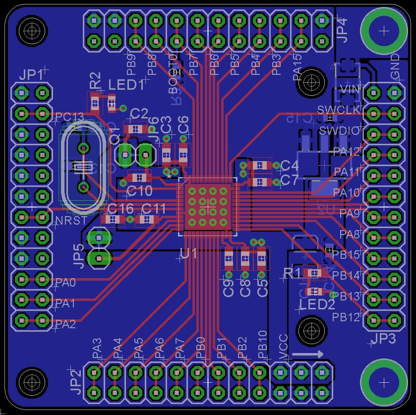
  • Microcontroller board

    Ryan Bailey06/09/2016 at 00:15 1 comment

    Just shipped a new board design off to fab. This time it's a small prototyping board for the STM32F411 microcontroller used in the camera capsule. I already have a Nucleo board for the purpose of prototyping, this board is to prove to myself that I can build up a functional system from scratch using this particular microcontroller. It integrates a 2.8V regulator and the option to forego an external crystal - both of which are requirements for the final system.

    I expect the board back in a few weeks.

  • A Modestly Powerful Update

    Ryan Bailey06/07/2016 at 03:53 0 comments

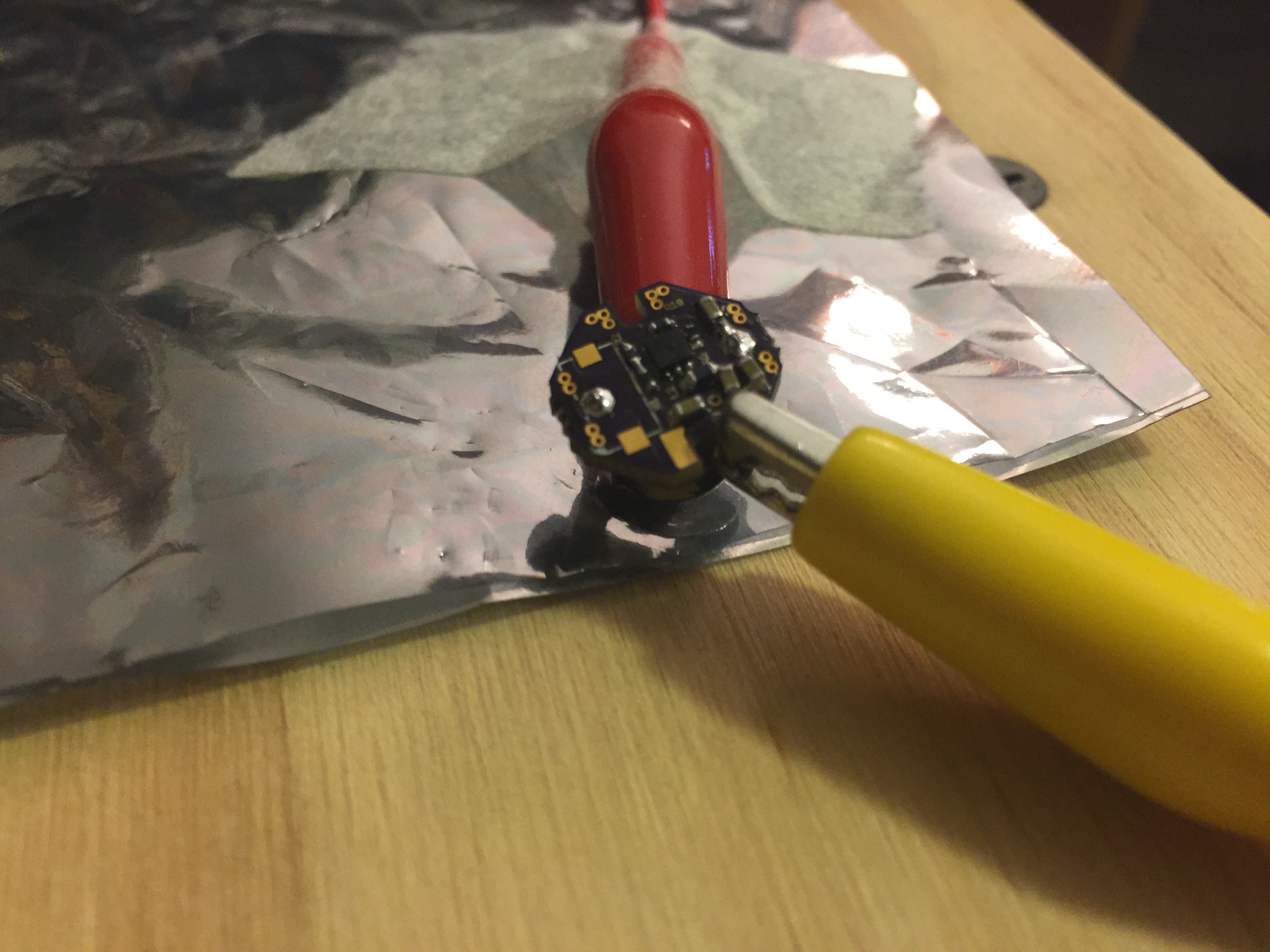
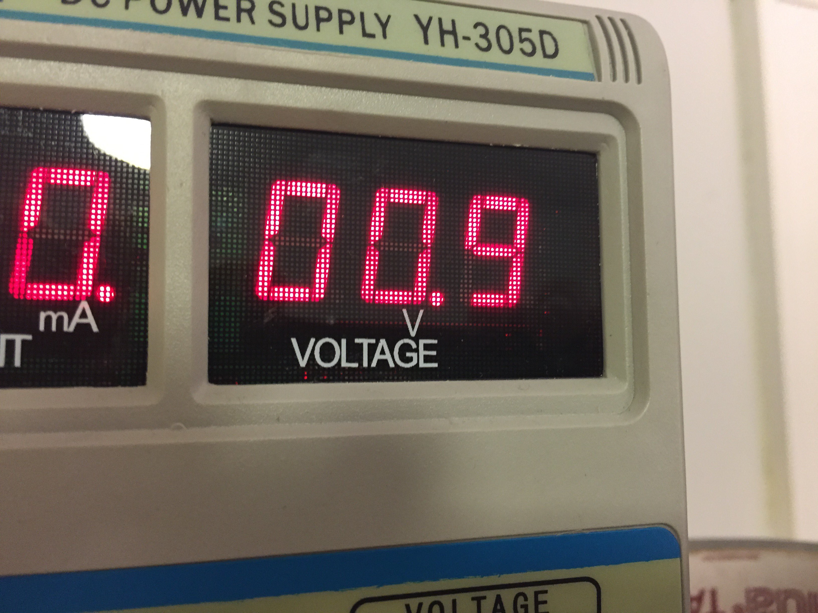
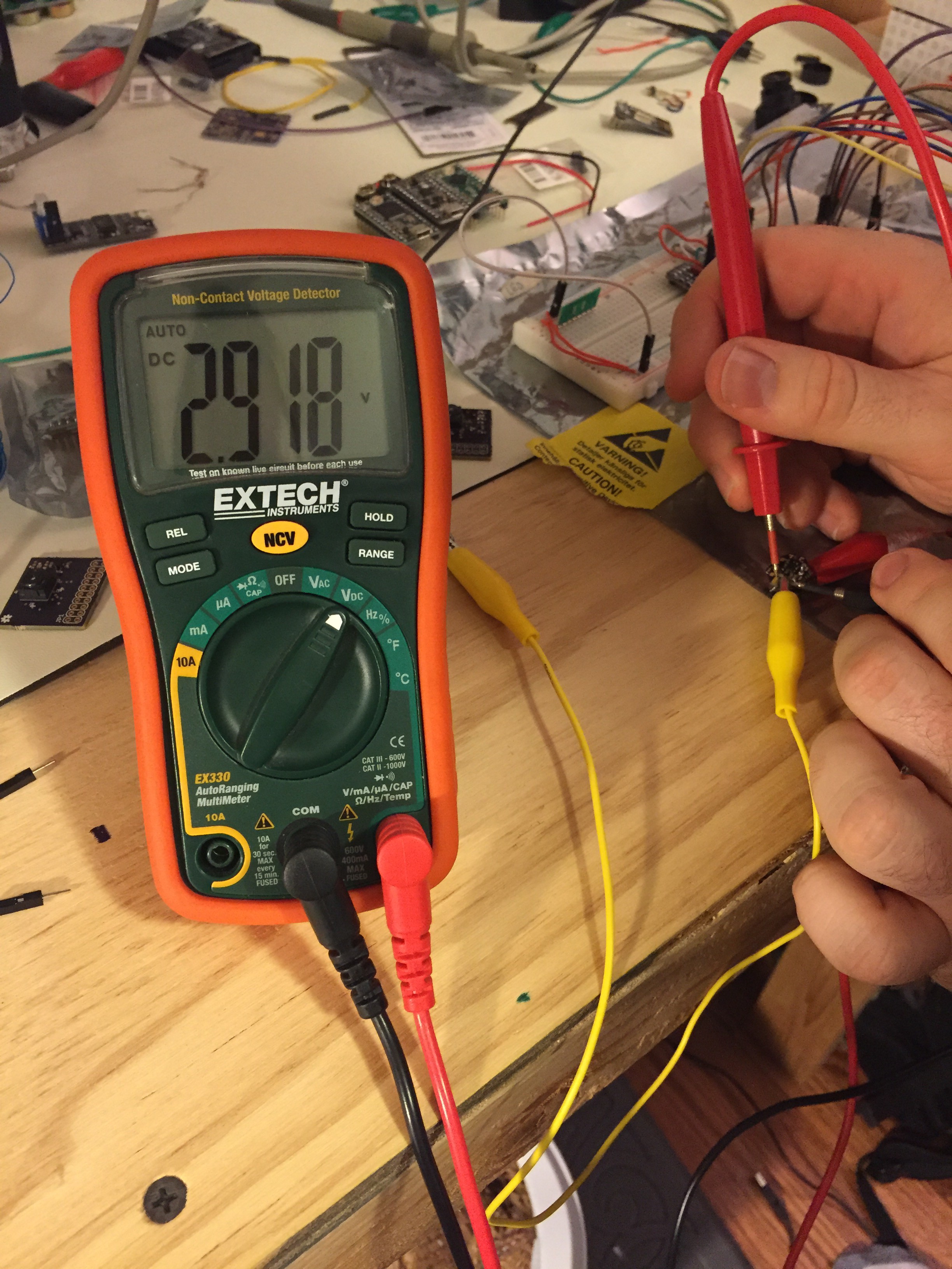
    The battery + boost converter board seems to be working. After a blown out board due to ordering the wrong inductor (note to self: triple-check BOM), things seemed to work pretty well. The boost converter accepts as little as 0.9V from the battery and outputs ~2.8V, the supply voltage required by the imager and therefore the common supply I'll use for all other components.

    The proof is in the molten lead pudding:

    Fully assembled (with the right inductor this time).

    Running at minimum voltage

    ~2.8-ish volts. Maybe 1% resistors next time.

  • Boards!

    Ryan Bailey05/16/2016 at 02:31 0 comments

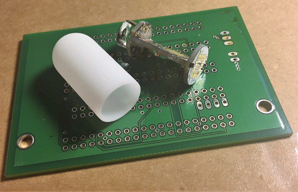
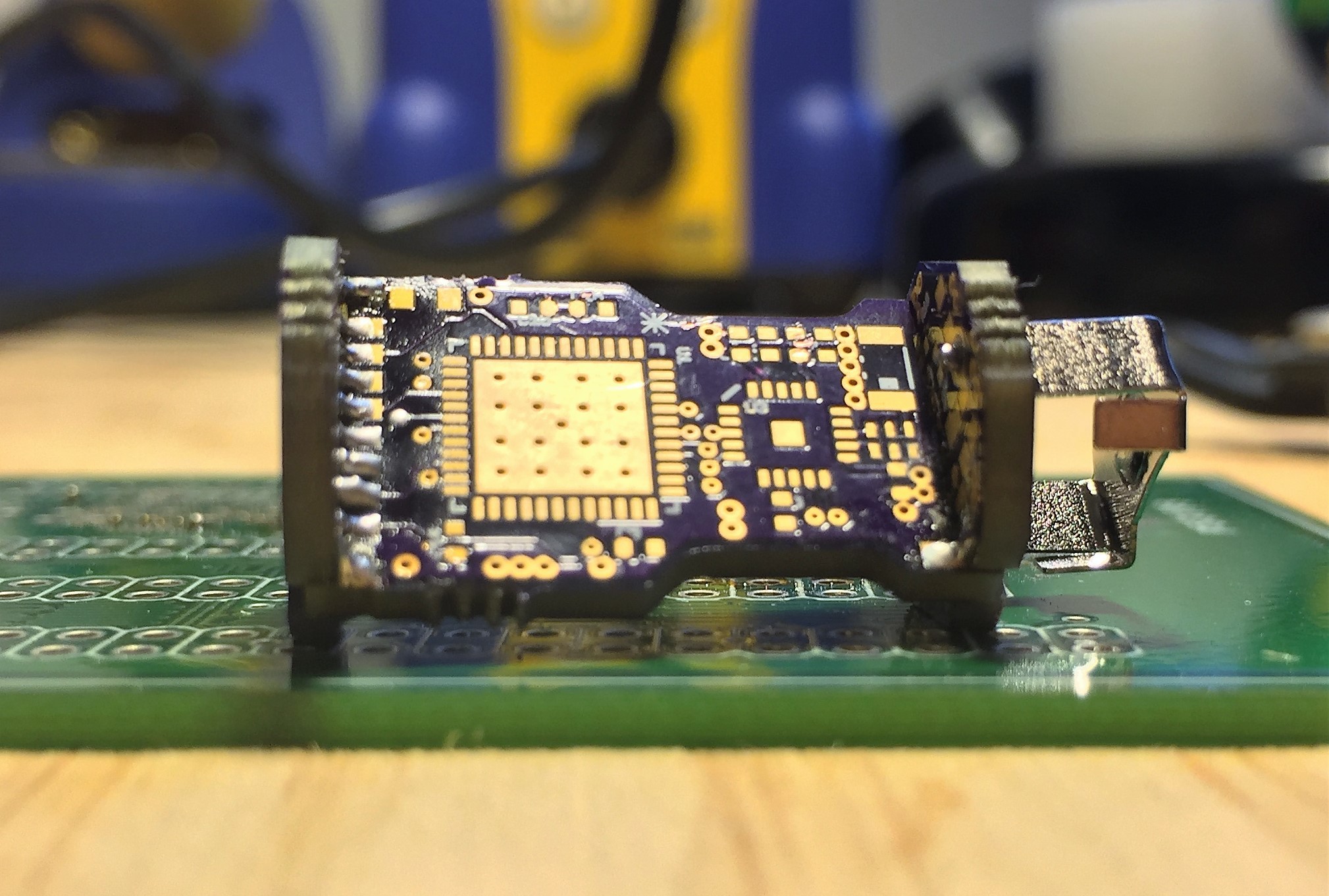
    I received a few dummy copies of the initial board design today. These are certainly not final but I wanted to get an initial look at how they fit together and identify any gotchas in the mechanical design. I'll solder one of them together in the next night or so.

    update 5/21/16:

    Rough mechanical check with the board-board connections soldered together:

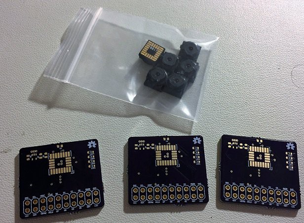
    Camera prototyping board:

View all 11 project logs

Enjoy this project?

Share

Discussions

Pal Dorogi wrote 10/18/2019 at 10:50 point

I think this project is dead now, it's sad as it was a good one.:)

  Are you sure? yes | no

Deltaprintr wrote 10/03/2019 at 23:23 point

Is this project dead? I would love to try one of these.

  Are you sure? yes | no

hzcmedcam wrote 12/08/2018 at 18:15 point

How is the capsule endoscopy project progressing? Can you demo it?

  Are you sure? yes | no

Pal Dorogi wrote 12/03/2017 at 05:45 point

Hi Ryan, 

Is this project dead now?

Cheers,

Pal

  Are you sure? yes | no

Ryan Bailey wrote 12/03/2017 at 15:01 point

Hi Pal,

Progress has been slow for several months due to moving and starting a new job. I plan to regroup around the holidays. Stay tuned!. Thank you for your interest.

-Ryan

  Are you sure? yes | no

Pal Dorogi wrote 12/04/2017 at 00:45 point

Ooh, cool thx.

  Are you sure? yes | no

ivan003003 wrote 06/11/2018 at 00:47 point

Thanks you very much !

This project is awesome .

  Are you sure? yes | no

Ming wrote 01/05/2017 at 13:47 point

Hi,Ryan-Where can I buy the ov2640

  Are you sure? yes | no

Pal Dorogi wrote 01/04/2017 at 10:58 point

Hi, Is there any update on this project

  Are you sure? yes | no

Ryan Bailey wrote 01/04/2017 at 14:20 point
Hi Pal - Updates are coming soon! I've been working on several things this month that I have not yet had time to document. Thanks again for following!

  Are you sure? yes | no

Pal Dorogi wrote 01/05/2017 at 08:02 point

Thx for the update

  Are you sure? yes | no

x893 wrote 10/19/2016 at 18:05 point

Easy to use STM32F446RC or RE with DCMI

  Are you sure? yes | no

Ryan Bailey wrote 10/20/2016 at 18:46 point

I agree that using the DCMI would be easier. However, I have not seen a DCMI-capable controller in a package suitable to my needs - preferably a QFN 8x8 or smaller. There are BGA and chip-scale packages that would work, but I'm trying to use inexpensive PCBs and ball pitch that small would not work.

  Are you sure? yes | no

x893 wrote 10/20/2016 at 19:09 point

I use 100 pin F407 for camera module (as OpenMV 1) but found this chip in 64 pin and want to test. BGA smaller but hard to soldering.

Good luck for your project !

  Are you sure? yes | no

[deleted]

[this comment has been deleted]

Ryan Bailey wrote 07/24/2016 at 18:46 point

Cool, I'll give that a try. I suspect the problem could also be a bad solder joint somewhere as the behavior improved somewhat after I re-heated a few areas.

  Are you sure? yes | no

Beppe Saracino wrote 05/25/2016 at 18:18 point

The most challenging and key aspects of the project are definitely 1) battery and integration of accelerometer - the first has to be safe for humans (at list for a while...) and the second is absolutely needed to locate seen-things, otherwise it is not useful for medical goals. I'm very interested to. Let me know if ever you'll sell (cheap) prototypes.

  Are you sure? yes | no

blackoise wrote 05/10/2016 at 16:18 point

Great project. I wonder: Does someone has any information about how to operate the parallel camera interface on the teensy, or how is the camera read out? Would be an interesting read. :)

  Are you sure? yes | no

Ryan Bailey wrote 05/11/2016 at 02:27 point

Thanks! One of the best starting references I found for getting a basic camera interface on the teensy was actually the following post in the teensy forums:

https://forum.pjrc.com/threads/31719-Cheap-Video-with-Teensy-3-1-and-5-OV7670-camera-chip

  Are you sure? yes | no

blackoise wrote 05/11/2016 at 14:46 point

Thanks a lot. :) Looks simple. Do you have an idea what performance could be archived with the OV2640 and higher XCLK?

  Are you sure? yes | no

fahd.muhib wrote 05/02/2016 at 23:09 point

Inspiring project. May the force be with you!!!

BTW, quick question: Did you do any worst case calculations for current draw to see how the silver oxide cell will accommodate for periods of high drain or during low BATT levels? I know for a fact that these Li-ion 3V button cells have high output resistance, which in turn, limits a board's capability to maintain stable rails during high current transients, e.g. during Tx/Rx operations on NRF modules.

  Are you sure? yes | no

Ryan Bailey wrote 05/11/2016 at 02:34 point

I agree that this is another challenging aspect of the project - these batteries are really best suited to constant small currents rather than large transient loads. I estimate peak transient to be about 20mA-50mA based on initial camera tests. The battery will actually be a silver oxide chemistry (nominal 1.55V) with a boost regulator to 2.8V to run most components on the board. A previous project of mine used one of these cells with intermittent current bursts to around 50mA without any problems.

Still, I have some more calculations and testing to do. A test version of the battery/power module PCB actually just shipped today. I will try to post an update when I get that far.

  Are you sure? yes | no

Domen wrote 05/01/2016 at 17:59 point

Are you sure STM32F411CE has a parallel camera interface? This mcu is noted in the components section of your project.


As far as I have just checked, it doesn't.  But maybe I'm the one mistaken though. Please check. 


Source: 
http://www2.st.com/content/st_com/en/products/microcontrollers/stm32-32-bit-arm-cortex-mcus/stm32f4-series.html?querycriteria=productId=SS1577

  Are you sure? yes | no

Ryan Bailey wrote 05/01/2016 at 18:19 point

It does not have a native camera interface. Still, that shouldn't preclude from operating the camera.

Edit: the F2 series appears to have native camera interface. However, none of the package options I see seem favorable to my size requirements for this project. I'm certainly open to suggestions because native interface would be more convenient from a software design standpoint. For now I may just have to continue with the plan to implement a camera interface through regular GPIO.

  Are you sure? yes | no

Psy Chip wrote 04/25/2016 at 20:23 point

also by adding an accelerometer it's possible to track pill position on body. by the way you have to give high priority to casing. due to battery, it will be fatal if got a leak.

  Are you sure? yes | no

Ryan Bailey wrote 04/30/2016 at 20:21 point

It's true that the casing needs to be good. Batteries can potentially cause burns and their contents are not necessarily something you want to digest. That being said, silver-oxide and lithium batteries are commonly used in medical implants. It's my understanding that the newer formulations of the silver oxide batteries contain little-to-no mercury these days. Still it's not something you want free in the body.

An accelerometer and other sensors would be fun to include - I don't know if this will physically fit in the current implementation. It would be interesting to see just how accurate (or not) dead reckoning would be given the long time window and the very small movements of the GI tract compared to the large movements of the body as a whole.

  Are you sure? yes | no

Psy Chip wrote 04/30/2016 at 21:02 point

in these days people talks a lot about cyber-implants. same design can be implemented to unused organs such as cecum (blind gut) by medical surgery. and can be charged by wireless chargers.

  Are you sure? yes | no

Gregor wrote 04/25/2016 at 12:35 point

Very nice project. Is a wireless image state-of-the-art for gastrointestinal imaging? I thought they were reading out the values afterwards since the body absorbs a lot of the wireless signal...

are you planning to produce and assemble the boards yourself? 

Have you already plans for the see-through part of the body?

  Are you sure? yes | no

Ryan Bailey wrote 04/30/2016 at 20:31 point

It may or may not be state of the art for pill cameras. There are a number of things the experimental or top-of-the-line systems do that I don't plan do attempt at this time. For instance, one type has a camera that spins inside a magnetic field for 360 degree views. Some models also use percutaneous power (electrodes attached to the skin) to send power (and communications?) to the device. There are radio SoCs that utilize the WMTS band and theoretically experience less interference from the body (essentially a big sack of water) than the 2.4GHz bands. Unfortunately, these devices are not easy to find or buy. Still, I propose to transmit only over a few feet so it's possible that it'll still work inside the body.

The plan is to do assembly myself - none of the components so far seem unreasonable to do myself.
I'm still pondering how to address the clear 'lens' end of the body.

  Are you sure? yes | no

Similar Projects

Does this project spark your interest?

Become a member to follow this project and never miss any updates