-
Image capture
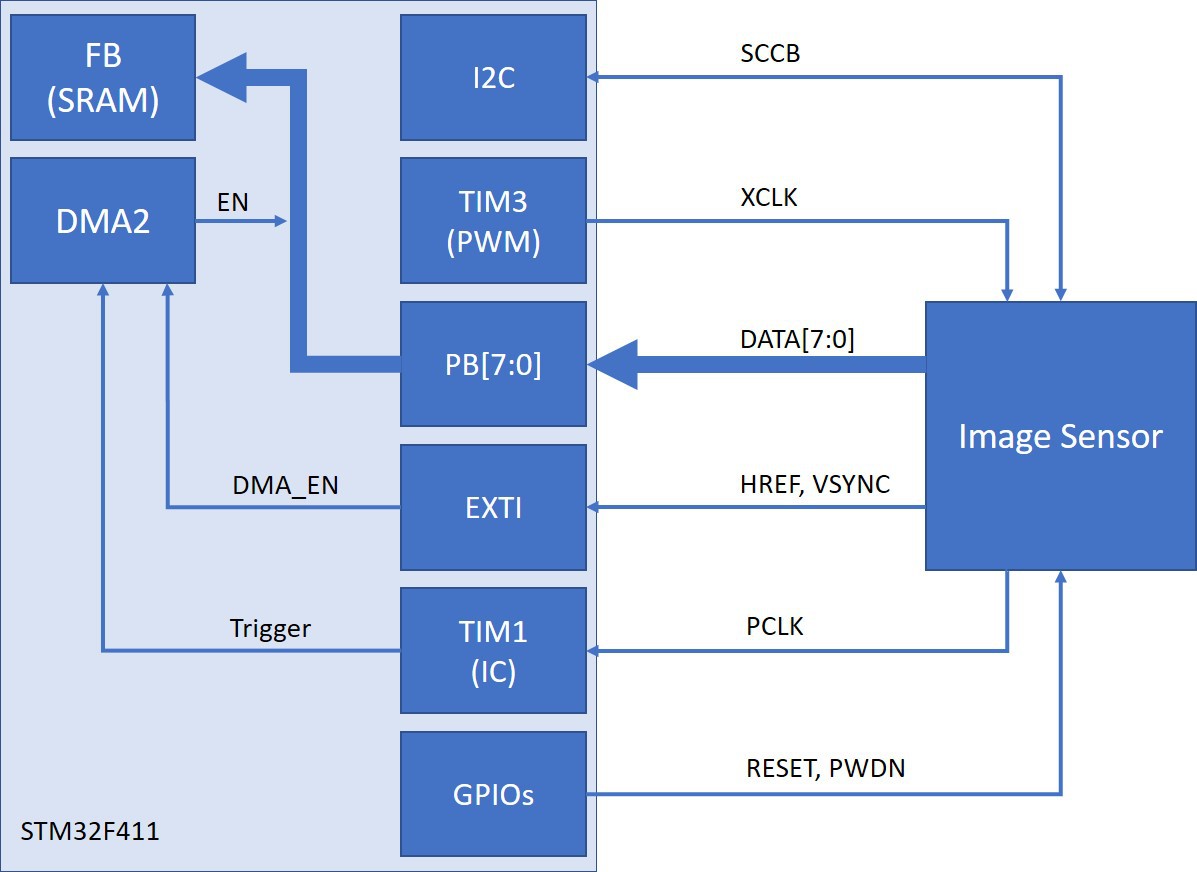
02/07/2017 at 22:43 • 0 commentsOne of the bigger challenges recently has been devising a way to capture output from the camera efficiently without relying on the DCMI interface available in other STM32 devices. One of my goals from the beginning was to avoid resorting to BGA or extremely fine-pitch parts. The idea was to keep board design and manufacturing relatively simple and cheap. Unfortunately, I have not found a DCMI-capable part with a sub-10mm diameter in a non-BGA package.
It is tempting to switch to something like the F407 or F429 (as found in the OpenMV). For now, I plan to forge ahead with the following strategy:
![Image Capture Block Diagram]()
Much credit is due to the following article (link) that outlines how to capture data using DMA triggered by a timer in input capture mode. ST also has a decent app note (AN4666) discussing general-purpose synchronous parallel data transfer that proved fairly helpful.
Full image capture should be available soon - there are still some kinks to work out with camera configuration.
-
State of the Project: Part 2
10/10/2016 at 03:39 • 0 commentsIt's been a good while since I've posted updates here. Several posts made earlier are more or less back-logs from the last three months, most of which I've been traveling to meet requirements for the rest of my education. Things are moving ahead and I have prepared a small video overview below:
Updates by specific system:
1. Camera: Progressing. Further tests needed once updated proto boards are assembled.
2. Power: Finished
3. Main Board: Updating Layout
4. Communications: RPi receiver implemented, command interface and display of received images in progress
5. Enclosure: Test enclosures working. Likely re-design pending new dimensions of board layout updates (see above).
6. Code: Test board and programmer working. Further coding efforts pending.
-
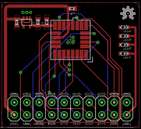
Camera footprint correction
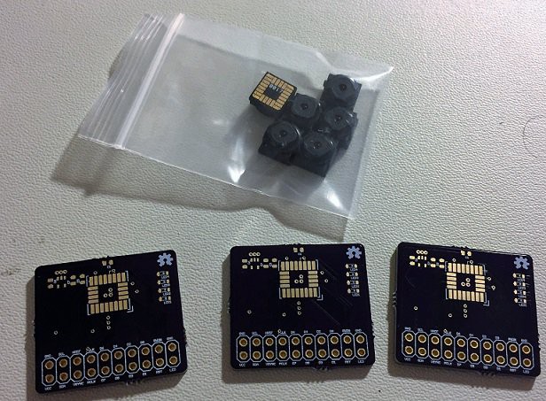
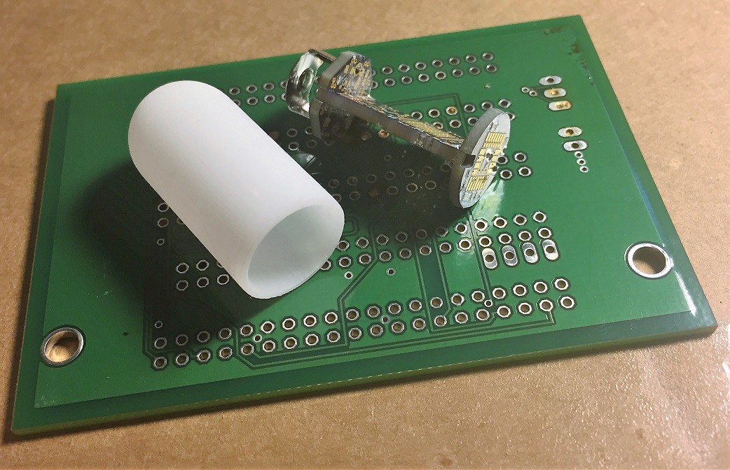
10/10/2016 at 03:20 • 0 commentsI usually do my best to check (and re-check) footprints before things go out to fab. Unfortunately, there was an error in the camera module footprint that shorted one of the power supply pins to ground. I think I had visually transposed a few things from the (minimal) datasheet on this device. Luckily, the fix was relatively easy and some replacement prototyping boards were sent to fab.
![]()
The replacement camera modules arrived just after I had left for two months on the road. I intend to find some time in the coming weeks to assemble them - especially now that I have a viable strategy for keeping the module housings from melting during reflow
![]()
Stay tuned.
-
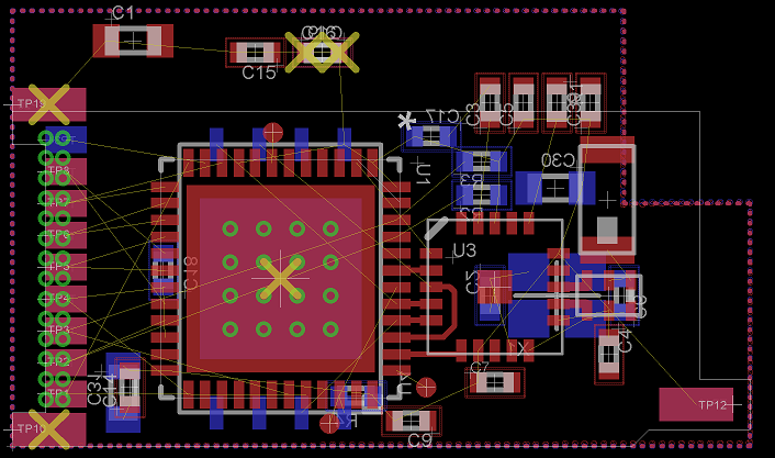
Layout Update
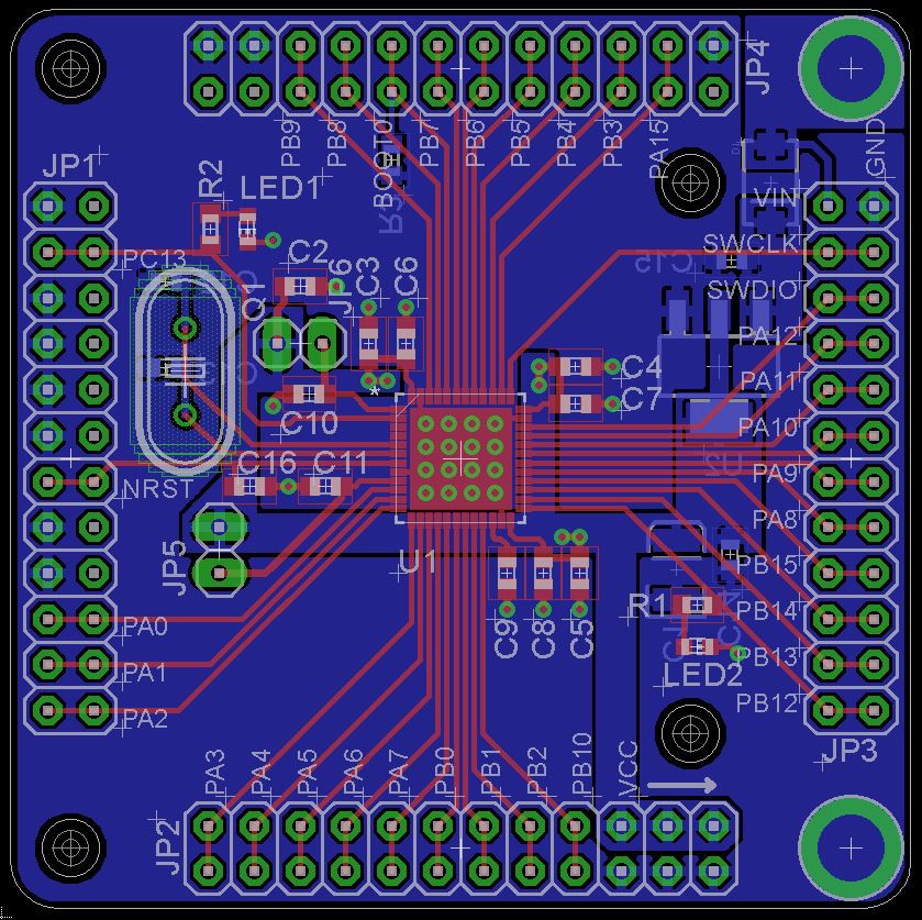
10/10/2016 at 02:51 • 0 commentsI spent some time during my travels going over the original layout. I've decided to take another crack at slimming everything down further - this means a main board width of 10mm or less. It's also a good opportunity, based on some previous dummy board assembly, to get the board-to-board approach right. I'm particularly interested in how far I can push down the size of castellations.
![]()
Obviously, still a work in progress. The goal is still to get everything on the same board using 0402 passives and OSHPark 4-layer spec DRCs. You can see why a lot of commercial units use flex circuits extensively.
-
Receiver Setup
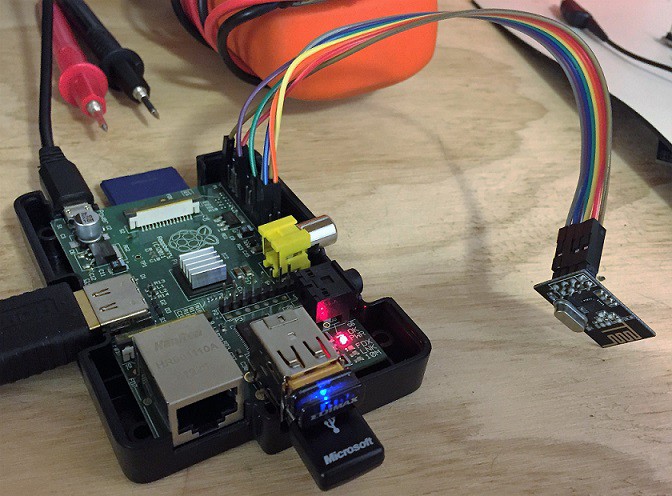
10/10/2016 at 02:38 • 0 commentsRadio update: configuration and sensor data will be received by an external device, in this case a Raspberry pi with a nrf24L01+ module attached.
![]()
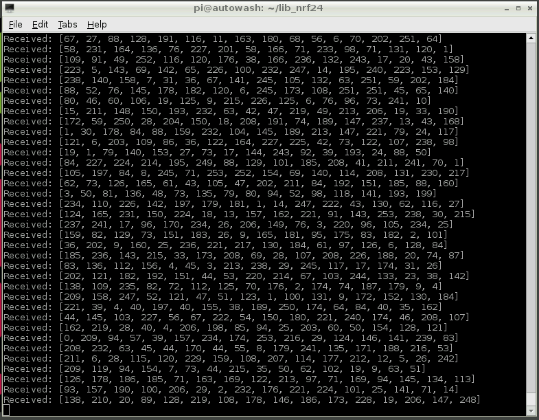
Right now I'm simulating 16-byte image packets sent from the capsule camera to the RPi.
![]()
Next steps include implementing full back-and-forth communication and displaying received image data on the RPi.
-
Microcontroller board update
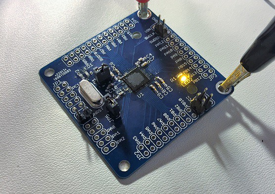
07/15/2016 at 03:26 • 1 commentUpdate: Initial programming was a modest success. There is still some temperamental behavior to work out with the programmer - some searching suggests that termination/reflection issues on the data line sometime cause programming to fail. Still, I was able to load and run a simple LED blink program:
![]()
It's been a busy couple weeks but I finally found the time (and the correct parts) to finish assembling a couple of the microcontroller testing boards that I cooked up last month.
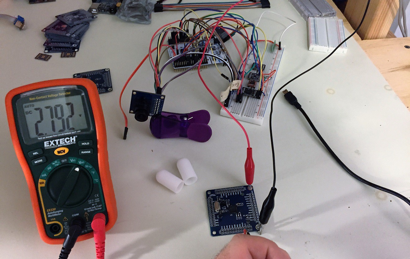
![]()
Also pictured: complete mess-of-wires version of the final system. The main voltage rail is 2.8V, regulated from 4-5V input, as required by the camera.
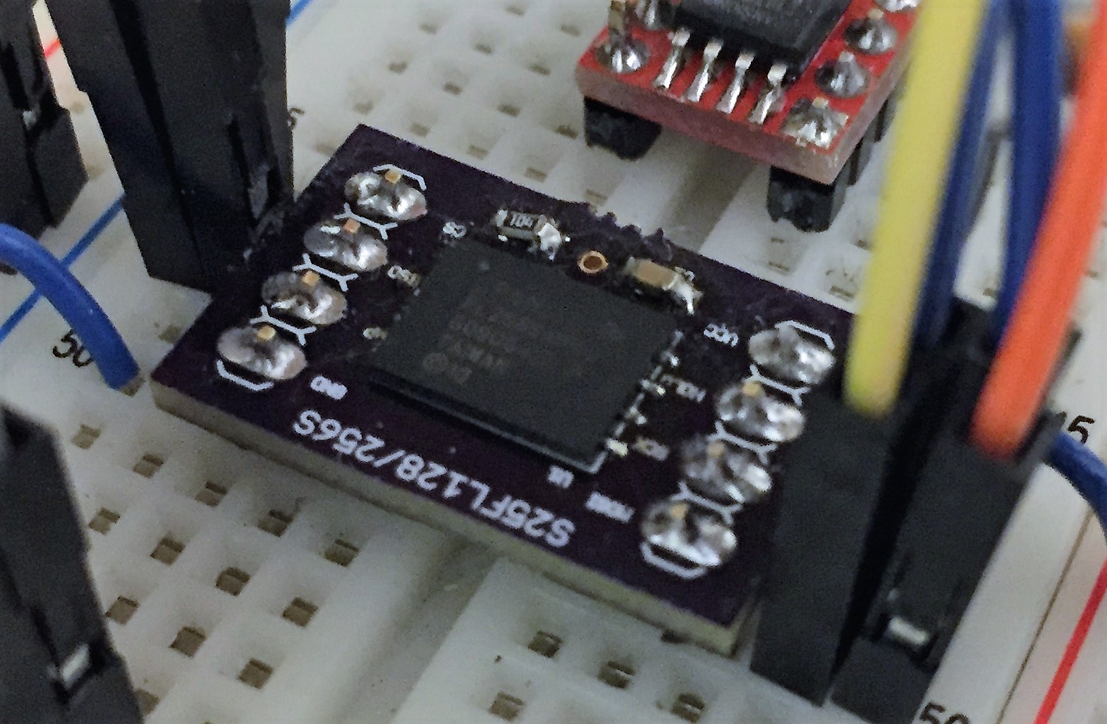
Also notable is the quick proto board I threw together for the 256Mbit flash device. It's a slightly weird-looking package so I wanted to try a standalone board before 100% committing it to the final design.
![]()
No magic smoke so far. Programming tests coming soon.
-
A quick update
07/01/2016 at 15:56 • 0 commentsIt's been a busy couple weeks with the school year ending. Subsystem software prototyping is almost finished. Most of what I've accomplished so far has been under the mbed environment, but sometime in the coming week or so I'll be ready to start transitioning over to writing specifically for the STM32F411 micro. Speaking of the F411, the proto boards are back and assembly will start sometime today:
![]()
Also of note, I had a handful of dummy enclosures 3D printed through the Dirty SLA service over at dangerousprototypes (http://dangerousprototypes.com/store/print3d) just to get my head around the case size and any issues with the board fit (so far so good!).
![]()
-
Microcontroller board
06/09/2016 at 00:15 • 1 commentJust shipped a new board design off to fab. This time it's a small prototyping board for the STM32F411 microcontroller used in the camera capsule. I already have a Nucleo board for the purpose of prototyping, this board is to prove to myself that I can build up a functional system from scratch using this particular microcontroller. It integrates a 2.8V regulator and the option to forego an external crystal - both of which are requirements for the final system.
I expect the board back in a few weeks.
-
A Modestly Powerful Update
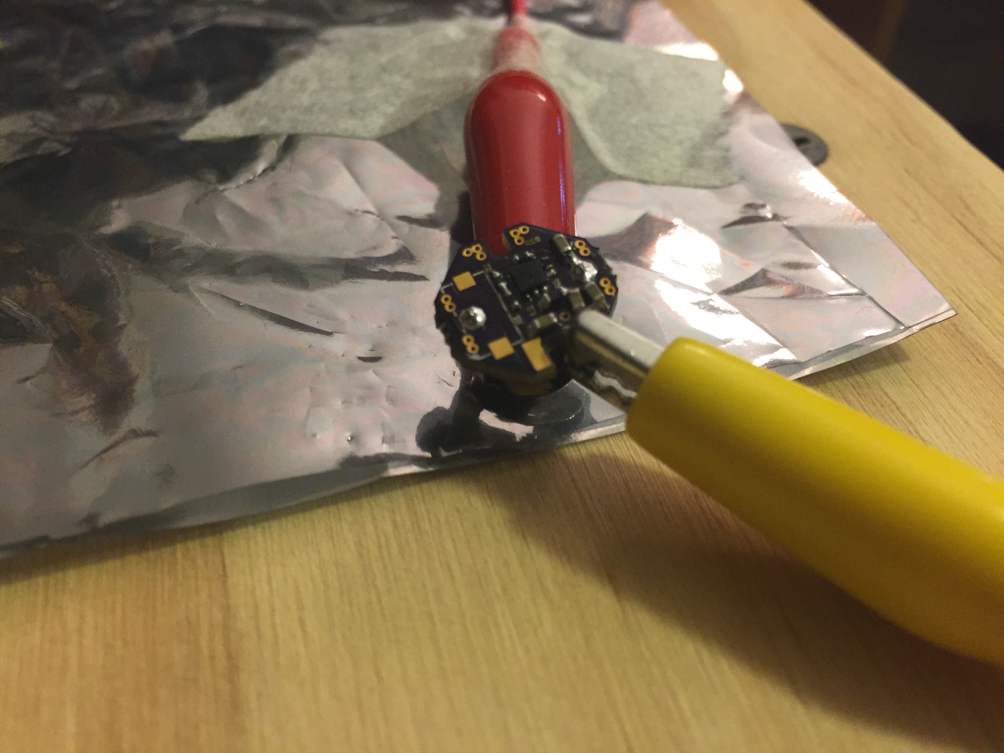
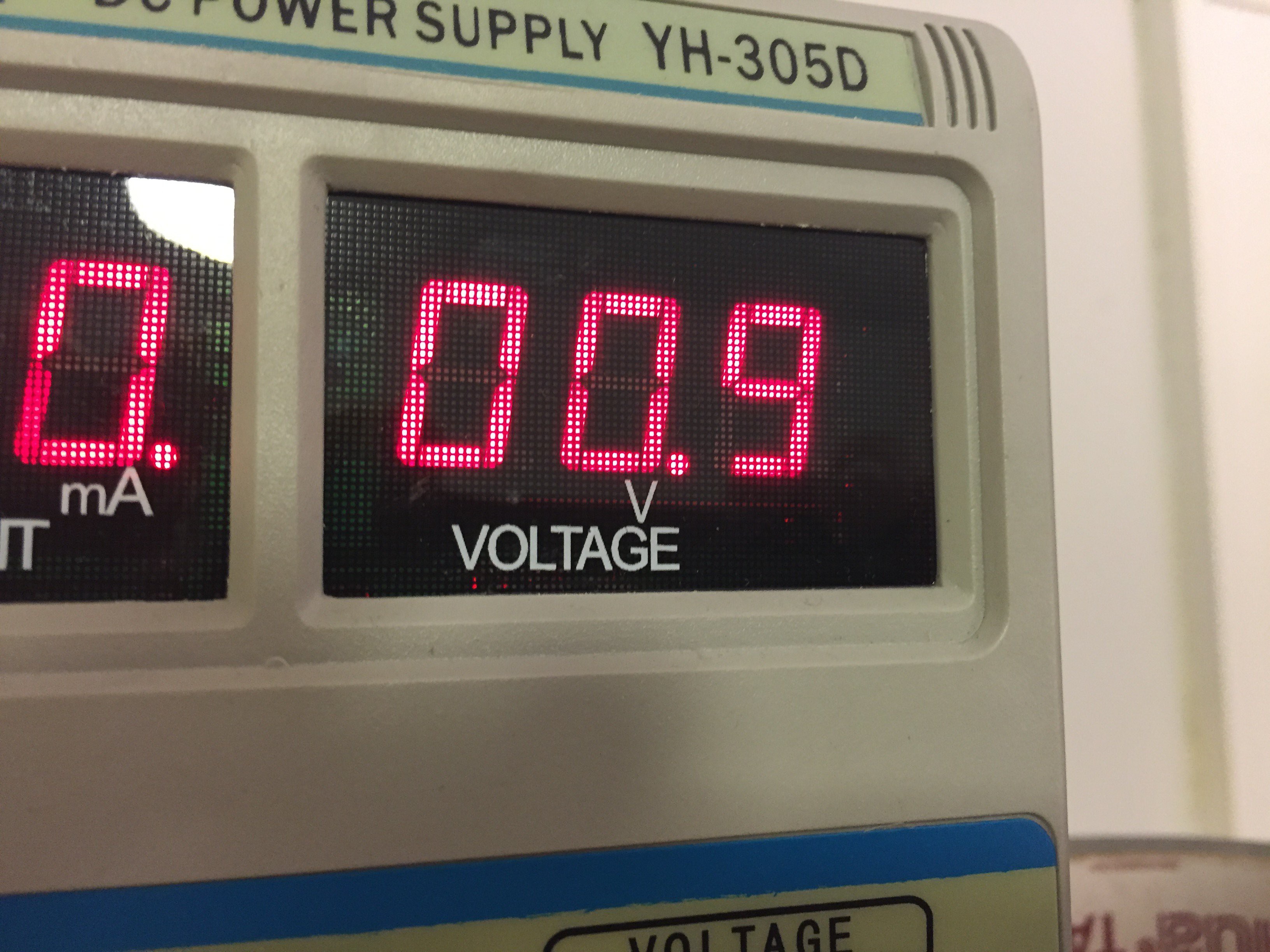
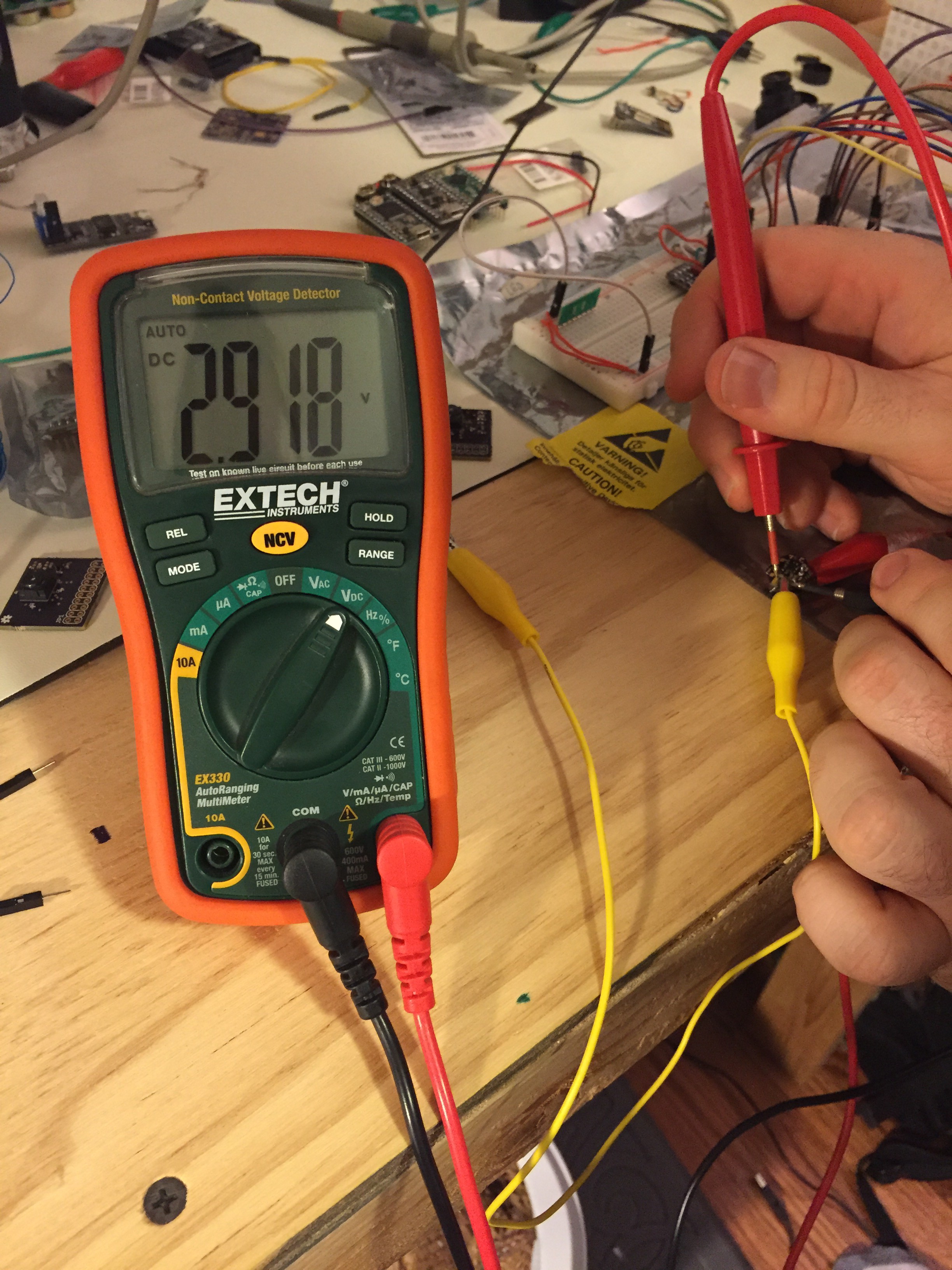
06/07/2016 at 03:53 • 0 commentsThe battery + boost converter board seems to be working. After a blown out board due to ordering the wrong inductor (note to self: triple-check BOM), things seemed to work pretty well. The boost converter accepts as little as 0.9V from the battery and outputs ~2.8V, the supply voltage required by the imager and therefore the common supply I'll use for all other components.
The proof is in the molten lead pudding:
![]()
Fully assembled (with the right inductor this time).
![]()
Running at minimum voltage
![]()
~2.8-ish volts. Maybe 1% resistors next time.
-
Boards!
05/16/2016 at 02:31 • 0 commentsI received a few dummy copies of the initial board design today. These are certainly not final but I wanted to get an initial look at how they fit together and identify any gotchas in the mechanical design. I'll solder one of them together in the next night or so.
![]()
update 5/21/16:
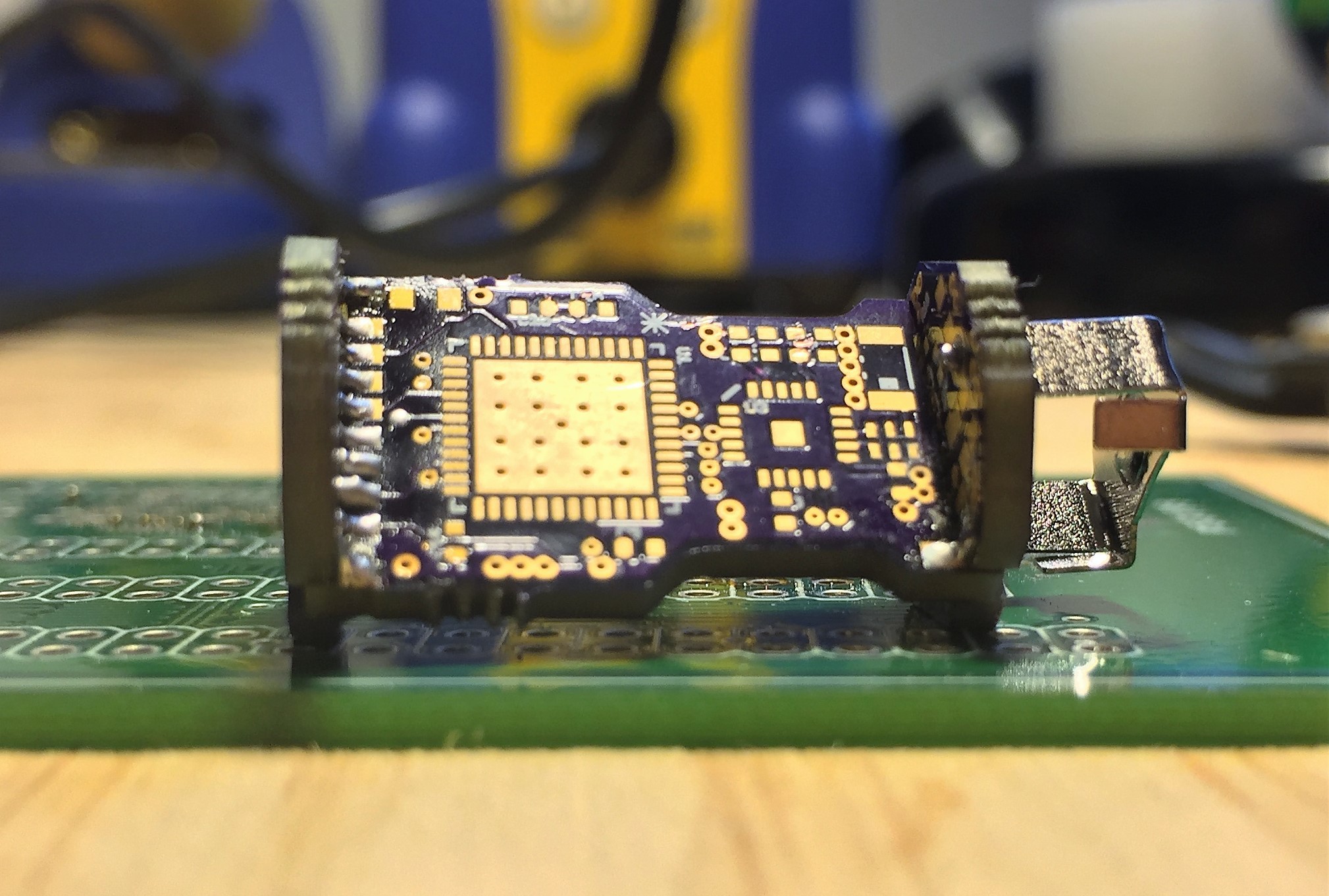
Rough mechanical check with the board-board connections soldered together:
![]()
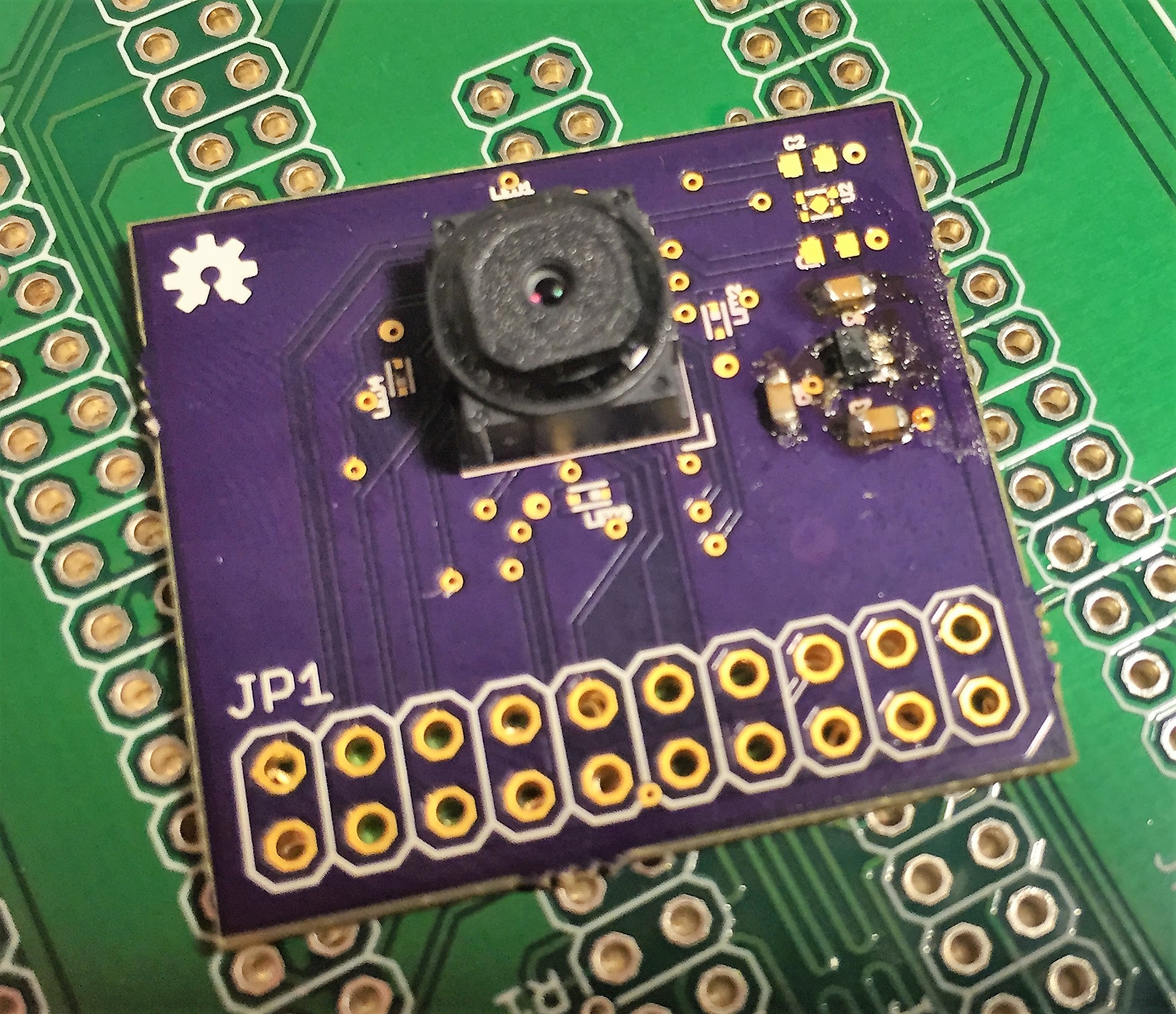
Camera prototyping board:
![]()
Tiny Wireless Capsule Camera
A tiny wireless capsule camera for medical imaging or space-constrained environments
 Ryan Bailey