Yann Guidon / YGDES
-
Input FET stage
04/28/2016 at 02:04 • 0 commentsI just received some BF256B and BF245C. I heard the 245 came after the 256 so I'll be able to test which works better, with enough supply to match a few pairs.
I haven't decided yet which instrumentation amplifier I'll use. This part of the analog domain still sounds like black magic to me but I know it must draw the least possible current and have a reasonable bandwidth (10MHz ?)
In case I can't find a suitable part, I can still put together a discrete op-amp with JFETs...
Interesting texts:
http://www.analog.com/library/analogdialogue/archives/47-10/discrete_amplifier.html (I wouldn't use high gain, unity is OK)
https://www.fairchildsemi.com/application-notes/AN/AN-6601.pdf (less advanced version but useful for estimating the noises)
http://www.forsselltech.com/media/attachments/JFET_Opamp.PDF (pretty cool tricks in the input stage but the impedance must be modified and I don't need the high voltage gain)
http://contifret.free.fr/ (discusses complementary vs non-complementary input topologies and JFET selection)This discussion is a direct consequence of my discovery of this circuit (I can't remember where)
![]()
The advantage of a full discrete solution is the ease to evaluate power consumption, for example. And there is no hard-to-find dedicated circuit.
So maybe the next log will focus on how to enhance a similar circuit (that is not dedicated to audio applications). I know already that it misses an offset compensation (with a simple trimmer) and a constant current source (another FET to replace R1).
-
BNC mess
04/15/2016 at 00:48 • 0 commentsWHY am I so stupid ?
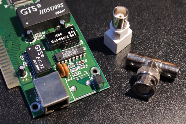
I desoldered the BNC connector from two ISA boards and then, the obvious finally trickled into my conscience...
![]()
The T doesn't have the expected gender, this is double female and I need double male !
I can't find T with 2 male connectors. So there are 2 solutions : solder directly on the T's shielding, or get male BNC sockets for PCB.
Right now, I'm choosing 1) while waiting for the order of 2) to be delivered...
-
Amplifier design
04/14/2016 at 08:47 • 0 commentsIn this forum post http://www.abcelectronique.com/forum/showthread.php?t=35757 one comment explains how a single-ended amplifier works, even providing this diagram:
![]()
The key part is a pair of closely matched and coupled N-FET (for temperature compensation). They can be replaced by a pair of BF256 that must be sorted/matched.
This circuit can be duplicated to become a differential amplifier, by also re-wiring the output op-amp (or using an instrumentation amplifier). The differential nature will also compensate for temperature drifts.
From this, 2 things become apparent :
- the symmetric power supply needs to be quite high-voltage so this is a direction for the design of the energy harvester.
- by selecting the proper components, the power consumption can remain within reasonable bounds (with obvious compromises in stability, bandwitdth etc.)
I have seen other, better schematics with higher performance but the cost and complexity become overwhelming. OTOH, a handful of BF256 (VHF N-FET) doesn't cost much.
The supply can be regulated by a couple of micropower LM4041 (initially intended for the ADC of the #Discrete YASEP), drawing only 60µA, capable of up to 10V of shunt (15V abs.max.) and 10mA of sinking. I don't think a scope's probe test point can provide such a current so it's well within the bounds.
Now, it remains to be seen how much the above schematic draws in practice. Linearity, bandwidth (frequency response) etc. are also a concern.
Maybe I'll have to complete my #Quick & Dirty Frequency Generator or buy that DDS from my dear friend noodlehead
![]() (No, I'm not shooting for GHz precision, my fastest scope reaches 200MHz only)
(No, I'm not shooting for GHz precision, my fastest scope reaches 200MHz only) -
System analysis and design
04/13/2016 at 10:52 • 0 commentsI have moved this from the details page because it became too large.
I expect the amplifier to draw a milliampere or more. This is not comparable to the DS32KHZ and a different solution is needed because the charge pump will not work at all.
The first question that must be answered is : how much power can the test point provide ? I don't think that there is a standardised design, my cheap scope provides 2V at 1KHz but it doesn't need to be precise because all it has to do is provide clean edges.
This lack of standardisation implies that the DC/DC design must be flexible and accomodate different frequencies, voltages and current ratings.
There are 3 usual methods to step-up :
- Charge pumps: already tried, accomodates low currents, simple, cheap but limited.
- Single-coil step-up converters:
some circuits can work down from very low voltage, like a used AA
battery, and increase the voltage to any desired level. There is one
problem though: they draw more current as the input drops. The quiescent
current is not negligible (some new chips get better though) but
basicly, the big drawback is that it hammers the source when it gets
weaker... leading to a catastrophic drop.
Integrated solutions might also have startup issues: the oscillation must start VERY fast because there are only 500µs per cycle to gather energy. The circuits I know have slow ramp-up time, like 10ms... This totally shatters any claim of high efficiency. - Resonant, double-coil converters:
So-called "Joule thief", these circuits are usually composed of a BJT, a
transformer and a diode. They have meaningful advantages and drawbacks:
- Power output depends on all the parameters and parts, including available input energy (output power will decrease with the input)
- cheap, easy to source, though the transformer is often tricky (single-coil versions are usually preferred)
- can generate relatively high voltages (but beware of the breakup voltage of the hashing transistor !)
- with a 3rd winding, can simultaneously generate negative voltages (great for analog amplifers!)
- startup is immediate (must be tuned and measured though)
- The transistor can die if there is no load connected to the output (been there, done that)
- Efficiency is not as good as a perfectly controlled IC (50% to 70% from my decade-old experiments)
From this, it appears that a "modified Joule thief" is the most promising solution. The ability to automatically adjust the input current and the output voltage are essential because they will vary all the time ! It can accomodate your brand and make of oscilloscope.
The step-up DC/DC is one thing but it will only work about half of the time. During the peak hours it will try to convert as much energy as possible. This energy is stored in a big capacitor before being used by a linear regulator.
This is where the design borrows from other established systems, in particular the "active PFC", power factor correction circuits that have to deal with the same kind of problem, when the rectified power from the mains (50Hz sine in Europe, 100Hz half-sines) does not provide energy during a significant fraction of the cycle.
The solution is to step-up as much as possible and store in a large capacitor that will provide the necessary energy during the remaining 500µs.
Some desired properties of the capacitor are:
- Low ESR (series resistance) and high quality, thus it's more expensive than a typical capacitor, or it will fail from internal heating (well, that's what I remember from past projects, we're speaking about some mA not Amperes here). Ringing can also be an issue.
- High voltage tolerant: the step-up can generate high voltage and the capacitor will switch continuously between charging and discharging
- Capacitance: it must be computed but 47µF was not enough in the case of the DS3KHZ. With the step-up, a large ripple is not a problem because the capacitor can be charged at 30V if needed.
So there is a trade-off between capacitance, ripple, voltage etc...
Note: the probe must be differential (plus a common pin) because some current (with nasty oscillations) will go through the ground-connected shield.
A split-system becomes necessary:
- one module (power supply) hooks directly on the scope's BNC socket to reduce the power current-induced interferences.
- 2 wires come out with +/- along the cable of the scope probe. The tip is equiped with the differential amplifier.
So that's why I went on a quest to find BNC connectors...
-
Hoarders' delight
04/13/2016 at 10:32 • 2 commentsDo you know that little voice that says "hey it's a cool bargain, don't miss it, you WILL need this junk one day, I am sure !"
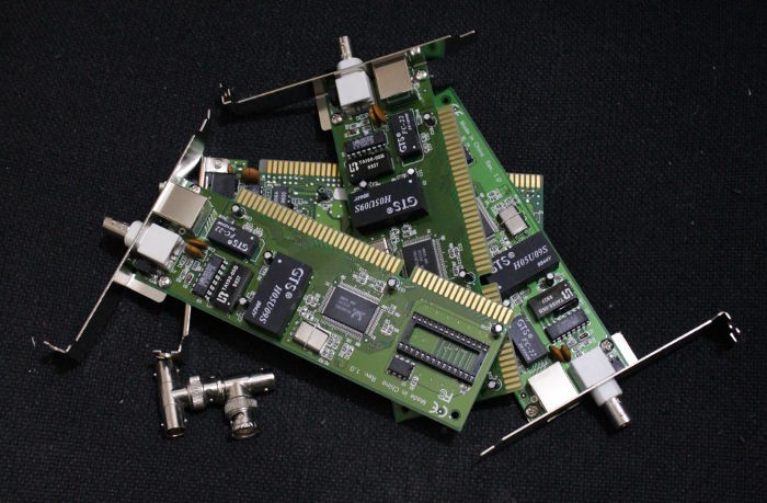
That was almost 13 years ago and I came across bargained ISA NE2000 cards. I had read somewhere that someone had hooked such a board to a PIC16F877 and written a network stack...
Fast forward to 2016: I use Wiznet chips, FPGA and the YASEP has been emulated and simulated. But I need BNC connectors and Ts. Wait, I don't need to go outside to the last electronics parts shop of Paris. I can desolder them from those boards :-D
![]()
The T were provided but I must have taken them all from the boxes, as I found a couple in the scope probes' box. Well, 2 will be enough for a prototype.
-
BNC trick
04/12/2016 at 23:58 • 0 commentsOne Signal Integrity issue is : no power should flow through the shielding of the scope probe, and in particular no changing current ! This would kill the sensitivity of the probe.
In the #ScoPower I use a short coax cable, and a crocodile clamp. The power supply that goes through the shielding is weak and there is not much influence. The output signal is square and even a tiny jitter is not critical.
If milliamperes have to flow at 1KHz, over a 1m coax, things are radically different. That is why there must be a separate circuit for power, at the BNC base, and the amplifier at the end of the coax. Both circuits are linked with another pair of wires for + and - supplies. The amplifier will just "drop" the voltage with a LDO, and eventually provide some feedback with a sense wire to decrease the voltage of the step-up...
One problem had been identified though : there is no male connector for PCB, only female (AFAIK). However I just found a little nice trick ! A simple BNC "T" connector has 2 male and 1 female sides so I can make a PCB with a female connector, which directly hooks to the scope and reduces the ground current in the coax's shield.
(I gotta draw a picture but I'd rather assemble a prototype instead)
Another issue is that most BNC coax cables are intended for 50 Ohms impedance but the probe scopes have a different impedance... You'll have to sacrifice a probe to connect to the amplifier :-/ Unless you can resurrect an old broken probe and cut its head...
Active scope probe with no dedicated power supply
Using the probe test point to power a ultra-low capacitance, high-input-impedance amplifier, essential for accurate analog measurements!
 (No, I'm not shooting for GHz precision, my fastest scope reaches 200MHz only)