 Tom Meehan
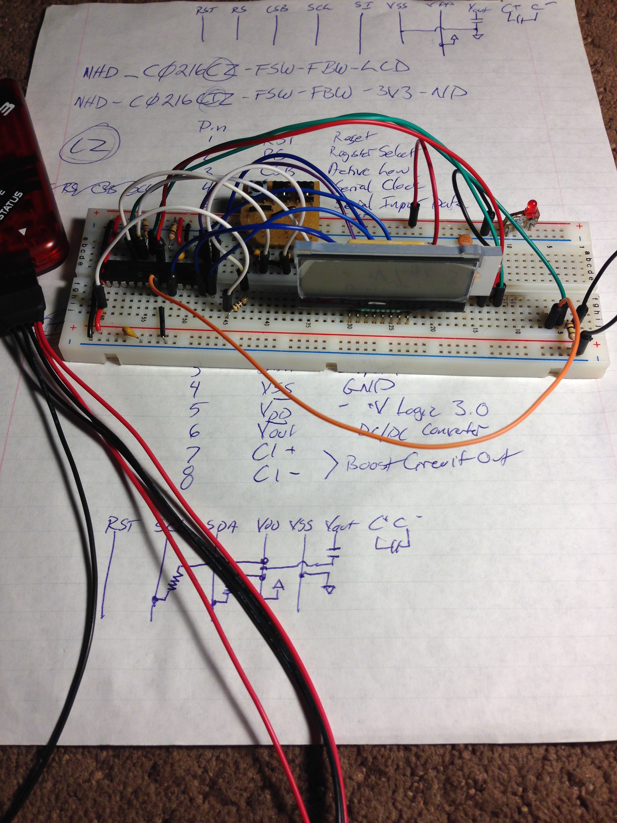
The LCD in Microchips Reference Design has a lead spacing I haven't seen before. So... I I used some strip board to make an adapter so it can fit into a standard 0.1”pitch breadboard. While adjusting the angle for better viewing I cracked the glass so I placed a new order for:
- new LCD
- additional capacitors (I thought I had all the ones I needed but found I missing a few)
- another PIC from the same series (16F1779 that has more memory and additional IO pins so that when the time comes I'll have additional pins for buttons for strip selection and more IO pins for the MultiStrip port - that I'm working on)
- some other PIC's to learn and experiment with
- Running through information in a few books, etc, to better learn PIC programming (C and Assembly)
I've finally gotten the reference/base coder from Microchip to compile without any errors, and finished bread boarding the reference design (well.. mostly, see below).
While finishing wiring the bread board I found that I have the incorrect LCD display. I ordered, and have, the C0216CiZ instead of the C0216CZ LCD display (it seems that now few suppliers carry the CZ and instead only have the CiZ display – both are 16 x 2 LCD displays but they are much different in pin out and use different protocols). There seems to be some code libraries for more standard 16 x 2 LCD displays, so I will attempt to implement them instead – since it will be easier for other people to replicate my final design.
Having never worked with PIC's before (only Arduino's and AVR's), editing and adding to code is challenging so far – but I am working at it every day and making steady progress.
Discussions
Become a Hackaday.io Member
Create an account to leave a comment. Already have an account? Log In.