Tom Meehan
-
GitHub, MPLABX, EAGLE... Oh my!
08/31/2016 at 05:56 • 0 commentsI've been delayed in posting my progress due to working on another project for the Chicago Southland Maker Faire. I was determined to build a Van De Graaff generator for some fun demonstrations of the effects of static electricity. I got it the Van De Graaff finished and working - but with the high humidity it couldn't due to much. Also, got to show off my progress on the Universal Glucometer.
Still trying to conquer linking my MPLAB X projects to my GitHub repositories (instead of committing changes I've been adding them manually - which defeats the purpose of GitHub, version control). This has been my biggest headache.
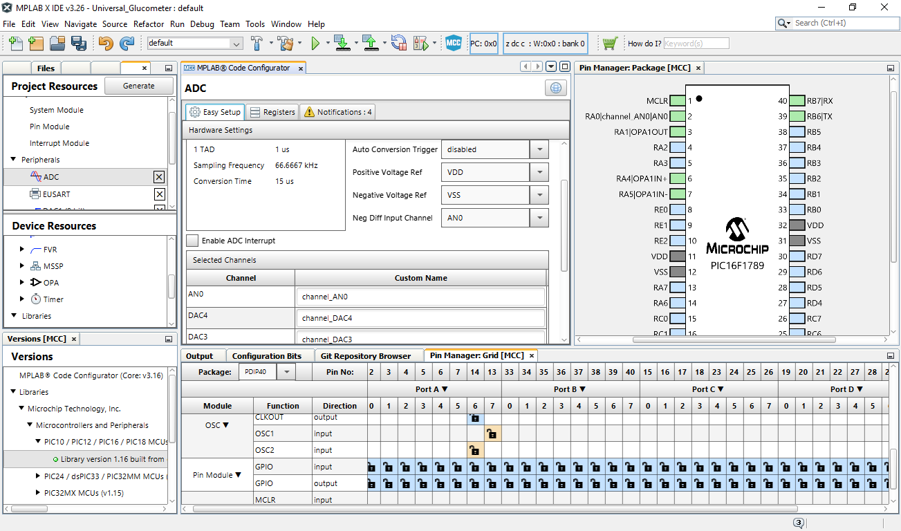
In the process of updating MPLAB X, I found the MPLAB Code Configurator. I completely missed this on my initial install. It looks like it can be quite helpful in generating the code to set up, configure, all the different parts of the microcontroller (ADC, DAC, OPAMP, INTOSC, etc.). I am presently attempting to use it for my upgrade/migration to the PIC16F1789 chip (more memory, and another Port).
screen shot of MPLAB Code Config.
![]()
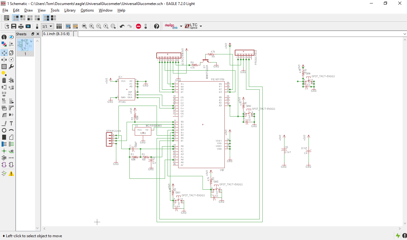
To migrate over to the PIC16F1789 and also add external EEPROM memory means that I have to move the LCD screen over to Port D - from Port C. This is because Port C has the pins to communicate with the EEPROM chip.
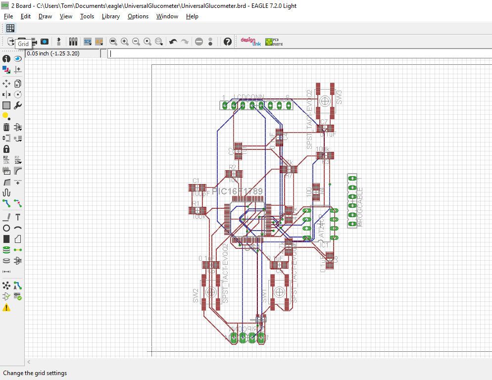
Still busy with Eagle - finalizing my board design. Still need to add the battery/power contacts, a ground plane, and room to add external communication (USB, Bluetooth) to download data, also would like to add a bootloader and usb connection to make updating firmware easier.
![]()
![]()
-
Keeping my head above water and making progress
08/16/2016 at 04:57 • 0 commentsWhile I've been able to find quite a few online sources for instruction in 'C', I really wanted a decent reference book (a physical one made of actual paper) to use. I finally broke down and ordered a copy of “The C Programming Language” by Kernighan and Ritchie.
I've been able to find a solution to an issue that's been vexing me for awhile – sending the values in variables out to the LCD.
char s[12]={0}; //declares a char array with 12 positions and clears the array
sprintf(s,"The value of J =",var1 ); // saves formatted characters, including 'var1' to the array 's'
LCDString(s); //sends formatted array to print on the LCD
So far this is working fine and lets me combine text and values from variables and print the results to the LCD. This was tough for me to figure out because it is something that seems to be obvious to anyone who has learned 'C'. Most courses on 'C' seem to cover 'printf' and 'sprintf' fairly early. So, being pretty new to 'C' and not formally taught I missed it - well now I will not forget that little piece of knowledge.
I've posted my most recent changes to the full source code at Github Universal Glucometer.
I keep reviewing the datasheets again and again. As I understand more I end up having even more questions and have to delve deeper to find the answers – it is slowly becoming less intimidating.
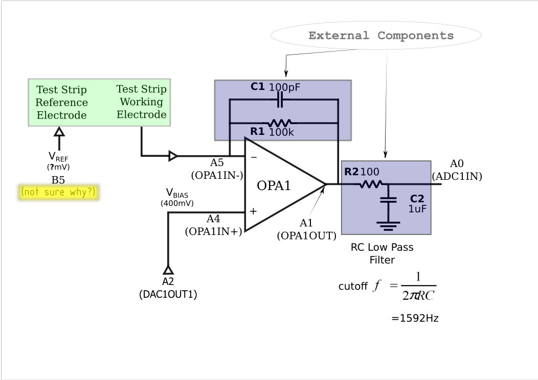
Illustration of the hardware/software implementation for strip reading.
![]()
Below is the Initialization code for the meter, the sets up the Fixed Voltage Reference, DAC, ADC, OpAmp, etc. (it is in the user.c file of the source code). This code shows the settings for the register pins in the illustration above.
void InitApp(void)
{
    /* FVR CONFIGURATION */
    //FVRCON = 0x88;
    FVRCONbits.FVREN = 1;
    FVRCONbits.CDAFVR = 0b10; //Comparator and DAC Fixed Voltage Reference Peripheral output is 2x (2.048V)
    FVRCONbits.ADFVR = 0b10;// ADC Fixed Voltage Reference Peripheral output is 2x (2.048V)
    // PORT A CONFIGURATION
    ANSELA = 0x3F;
    TRISA = 0x3F;
    ANSELAbits.ANSA3 = 0;
    TRISAbits.TRISA3 = 0;
    // PORT B CONFIGURATION
    TRISB = 0;            //PortB to output? then set individual bits?
    ANSELB = 0;           //Port B pins all set to digital++++
    TRISBbits.TRISB0 = 1; // PortB bit0 digital input STRIP_SENSE
    TRISBbits.TRISB5 = 1; // PortB bit5 digital input (REF_OUT Vref for strip)
    TEMP_SENSE_VDD = 0;
    TRISBbits.TRISB2 = 1; // PortB bit2 analog input TEMP_OUT
    ANSELBbits.ANSB2 = 1; // PortB bit2 analog input TEMP_OUT
    TRISBbits.TRISB3 = 1; // PortB bit3 digital input SW3
    TRISBbits.TRISB4 = 1; // PortB bit4 digital input SW1
    IOCBNbits.IOCBN4 = 1;
    IOCBFbits.IOCBF4 = 0;
    IOCBNbits.IOCBN3 = 1;
    IOCBFbits.IOCBF3 = 0;
    REF_OUT = 0;
    // PORT C CONFIGURATION
    TRISC = 0;
    //TRISCbits.TRISC7 = 1; //Rx is input
    // OPAMP CONFIGURATION
    OPA1CONbits.OPA1EN = 1;
    OPA1CONbits.OPA1SP = 0;
    OPA1CONbits.OPA1PCH0 = 0b1;// 0b10; // SELECT DAC AS INPUT TO  OPAIN+
    OPA1CONbits.OPA1PCH1 = 0b1;// 0b10; // SELECT DAC AS INPUT TO  OPAIN+
    // DAC CONFIGURATION
    DACCON0bits.DACEN = 1;
    DACCON0bits.DACOE1= 1;
    DACCON0bits.DACNSS = 0;
    DACCON0bits.DACPSS= 0b10;
    OPTION_REGbits.INTEDG = 0;
    OPTION_REGbits.PS = 0b111; // timer 0 prescale = 256
    // Enable interrupts
    INTCONbits.INTF = 0;
    INTCONbits.INTE = 1;
    INTCONbits.GIE = 1;
    INTCONbits.PEIE = 1;
    PIE1bits.ADIE=1;
    INTCONbits.IOCIF= 0;
    INTCONbits.IOCIE= 1;
    VREGCONbits.VREGPM= 1;
}
For additional information about the different modules (OpAmp, DAC, ADC, Comparator, FVR) I've listed the page numbers of the data sheet for the PIC16F1784 (includes -84, -85, -86 and -87) that each module begins on.- OPAMP Module p185
- DAC Module (digital to analogue converter) p189
- ADC Module (analog to digital converter) p167
- Comparator Module p193
- Fixed Voltage Reference Module p160
I've been concerned about the bias voltage for different test strips and I was happy to find that it is possible to adjust the outputs from the DAC's through the software/firmware and adjust the bias voltage.
The other issue I'm working to resolve - the Vref supply to the strip. Currently this is assigned to RB5 (which is configured as a digital input). I believe the Vref should be a negative polarity (so configuring the pin as an input makes sense) but I do not see regulation of the potential (V-). So, to begin I'll need to read this pin to see what it's potential is with reference to GND and to 3.3V. I'll be checking this ASAP, since it could have direct implications on my board design.
Additional pieces of the design I've been working on:
- Adding NPN transistor to switch the back light of the LCD on, when switching on from sleep mode. (I choose an NPN bipolar transistor instead of a MOSFET because the older NPN's are pretty easy to source, or even pull off of old circuit boards).
- Power supply. My current plan is to use 3xAAA batteries with a low
dropout 3.3v regulator.
- While it would be nicer to use a lipo cell with a charger circuit I feel that AAA batteries are easier to acquire iand less expensive than a lipo cell and charger circuit.
- PCB Design
- I am working hard to re-configuring the reference design (along with my changes) to port it to the PIC16F1789 chip (it's about the same cost and has more IO pins and on board memory). I'm also adding an additional EEPROM chip to expand the memory for storing the settings for regression equations (slope and intercept values), settings for the reference and bias voltages, etc. Basically, the data needed to change settings for on the meter to read different brands (and lots) of strips. I want to leave room to be able to transfer the saved testing data to another source and upload additional data to read more strips.
- Hopefully I can finish the basics for this in the next day or 2 so I can order boards from OSHPark that include current functions and break out the pins needed for the additional functions I would like.
I'll be posting up the new schematics shortly, that includes the changes mentioned above.
-
Drowning in a 'C' of code
08/08/2016 at 04:36 • 3 commentsThe Nokia 5110 LCD is such a nice, small, multi-line display (as well as fairly inexpensive and ubiquitous) that I've been determined to use it for this project. I've worked through code from a number of sources, some use proprietary compilers (like MikroC) and other are written for different chip series (PIC18F, etc.) or require purchasing the right to use the code. The one source that has been most useful to me is Nokia 5110 Example C source – PIC16F, which I mentioned in an earlier post.
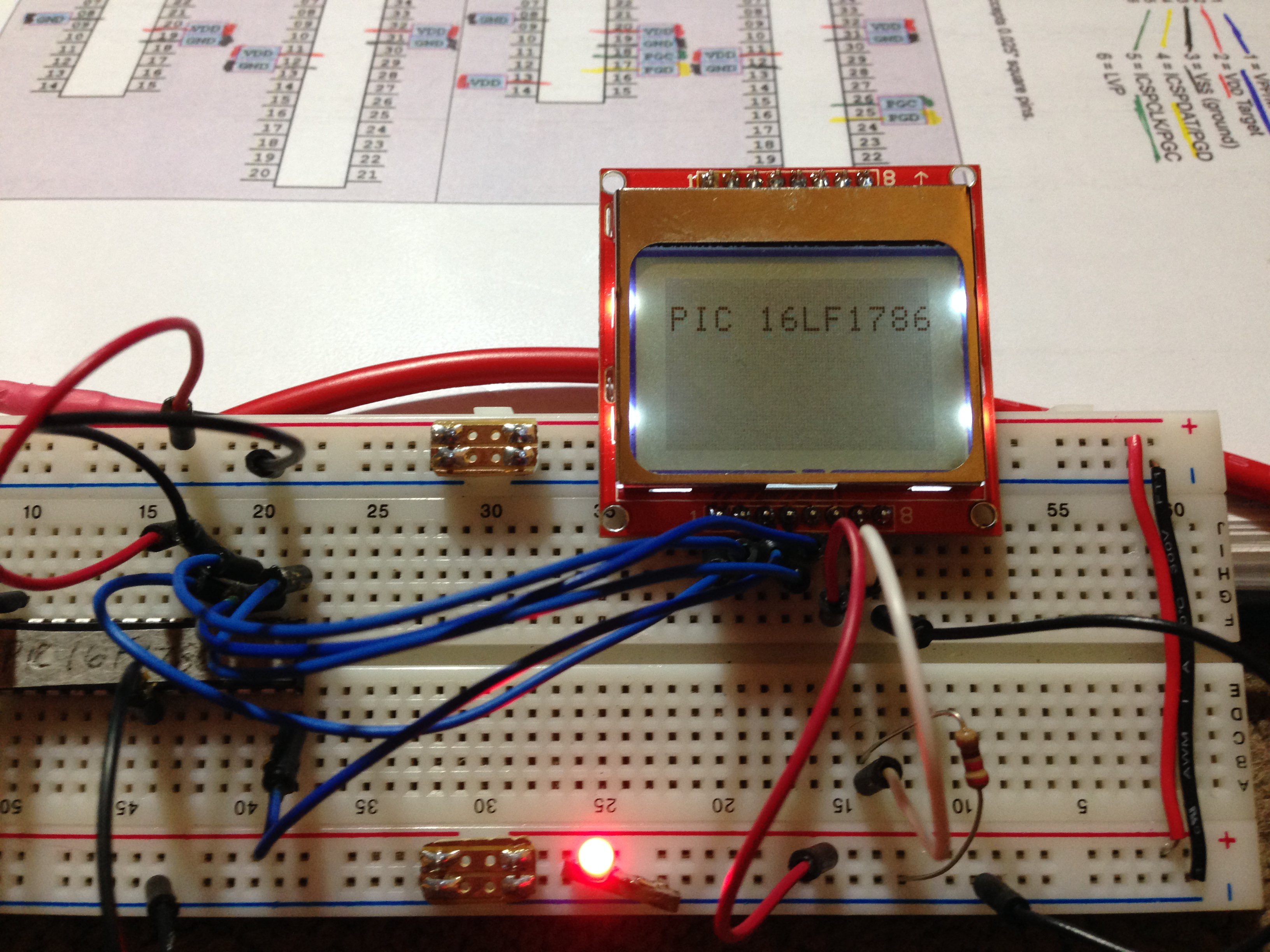
Changing pin assignments was the first order of business and was thankfully pretty straightforward (one important note is that I changed from a 5v to a 3.3v supply - I'm stating it now because I don't think I did in any earlier posts). Below is the code assigning Pins on the PIC16F1786 and corresponding pins on the Nokia 5110:
/******************************************************************************/
/* User Defines                                                                            */
/******************************************************************************/
//          Connections from PIC to LCD and LCD to Power
//                            LCD GND              LCD 8 on Nokia 5110
//                            LCD Backlight       LCD 7  to GND
//                            LCD V+ 3.3            LCD 6
#define LCD_CLK LATCbits.LATC5  //Pin 16 on PIC16F1786  LCD 5
#define LCD_DIN LATCbits.LATC4  //Pin 15               LCD 4
#define LCD_DC  LATCbits.LATC3  //Pin 14               LCD 3
#define LCD_CE  LATCbits.LATC6  //Pin 17                LCD 2
#define LCD_RST LATCbits.LATC7  //Pin 18               LCD 1
//The DC pin tells the LCD if we are sending a COMMAND or DATA
#define LCD_COMMAND 0   //Logic Low sent to DC to indicate sending COMMAND
#define LCD_DATA  1     //Logic High sent to DC to indicate sending DATA

#define _INTOSC 800000 //Internal Oscillator set to 8MHz
/*Even though using Internal Oscillator have to set XTAL Frequency
to enable __delay_ms() function*/
#define _XTAL_FREQ 800000

//Nokia 5110 is 84 by 48 pixels
#define LCD_X     84
#define LCD_Y     48
The first issue I encountered was trying to display lower case characters. Letters would come up but they were not the correct ones, so the search was on to find out why. Looking at my printouts of the code didn't find anything. I decided to look at just where errors began to appear – just looking at alphabetical characters it found that lower case 'a' was the first letter and it was switched to lower case 'b'. Looking closer at the code for characters I noticed that the text after the line for the '\' character was displayed in a lighter text. As it turns out the comment on the line signifying that it stood for '\'commented out the following line which is for the lower case 'a'. This then shifted the rest of the table forward one value.//array for character display data const unsigned char ASCII[][5] = { {0x00, 0x00, 0x00, 0x00, 0x00} // 20 ,{0x00, 0x00, 0x5f, 0x00, 0x00} // 21 ! ,{0x00, 0x07, 0x00, 0x07, 0x00} // 22 " .............................................................continuesThis is where the problem was:
 ,{0x00, 0x7f, 0x41, 0x41, 0x00}    // 5b [
 ,{0x02, 0x04, 0x08, 0x10, 0x20} // 5c \
 ,{0x00, 0x41, 0x41, 0x7f, 0x00}    // 5d ]
I changed it to the following and it works correctly now:,{0x00, 0x7f, 0x41, 0x41, 0x00} // 5b [ ,{0x02, 0x04, 0x08, 0x10, 0x20} // 5c “\” need quotes or it skips next line seeing it as a comment ,{0x00, 0x41, 0x41, 0x7f, 0x00} // 5d ]I've been trying all week to understand how I can send graphic bitmaps. Using LCD_Assistant. I'm able to generate hexadecimal arrays in C. I just haven't figured out how to send them to the LCD correctly – my code compiles but no graphics appear on the screen. I shelved this issue for later and decided to look at how characters are encoded in the ASCII array. Having read the datasheet for the Nokia 5110 display, and driver plus numerous code examples for sending text to the Nokia - I knew the most common font used 5 bits wide by 8 bits high (5x8 pixels on the screen). Looking at the code above you can see that each letter is assigned 5 hex bytes which equals 5 wide by 8 high. To verify this I plotted out some lines of the array on graph paper:
![]()
Editing unused characters in the ASCII file I've been able to make 5x8 graphics (blood drop - visible above).
My next challenges were figuring out how to insert calculated values from variables into the text I send to the LCD. This took me quite a while to figure out since I couldn't think of how to even state the question clearly. As it turns out, this is generally covered early for people taught 'C' and involves using printf and sprintf.
I'll try and go over this tomorrow.
-
Further adventures in learning to program PIC's
08/02/2016 at 07:33 • 0 commentsSwitching from the Arduino programming environment to programming PIC's in C is a significantly steeper learning curve than I initially expected - I had just started learning to program AVR's using C but his project has taken that to a different level.
I'm not complaining, just revealing my inexperience with using more standard C, as opposed to the Arduino IDE programming language (which is derived from C).
While there seem to be some easier to learn development environments with compilers that have a greater set of included functions/libraries to support peripherals components (like the Arduino environment does) I've decided to stay with the MPLAB X IDE that is free from Microchip.
This means I'm sticking with XC8 for my compiler and I'm doing this for a number of reasons:
- It's free, so open for everyone to use (making it easier to adapt/change the source code)
- The base code I'm adapting is written using XC8 as the compiler
- Last but not least – I've put in a significant amount of time learning to use it (I've only scratched the surface but starting over with something else would involve to much time at this point)
In the next day or 2 I'll post details of my adventure with porting code to allow me to use the Nokia 5110 lcd with PIC's. (I decided to switch to the Nokia 5110 LCD because it is widely available, cheap and much more compact than standard 16x2 LCD, like the HD44780 varieties).
-
Standard Test Solutions for the meter
07/24/2016 at 04:22 • 2 commentsAnother, very important, part of this project is developing a method of calibrating the meter to different strip profiles and different lots of the same strip.
For a bare minimum, we need 2 known glucose control solutions – so we can determine the slope and intercept of the strips response (linear regression – fairly simple algebra). We need a bare minimum of 2 points to define a straight line (y=mx+b). I initially believed that this would not be an issue since their must be standard glucose control solutions on the market for calibrating glucose meters. As it turns out this is not true, something that M. Bindhammer figured out a few weeks ago developing his Open Source Arduino Blood Glucose Meter Shield (another 2016 Hackaday Prize entry that is going into the finals).
After a bit of research (journal articles, patents, msds sheets – you can check out my reference post to access them), I found that these control solutions are made up of the same basic components:
- Water (major component)
- Viscosity enhancer (thickener)
- Preservative (antimicrobial)
- D-Glucose (Dextrose)
- Color (to visualize filling, does not appear to have any other function)
Patents and Pharmaceutical compounding trade journals provided lists of both viscosity enhancers and antimicrobials.
Viscosity enhacers (not an exhaustive list) :
Natural Hydrocolloids
-
- corn starch
- potato starch
- arrow root
- acacia
- guar gum
- xantham
- amylose
-
Other Enhancers
- hydroxyethyl-cellulose
- hydroxypropyl methyl cellulose
- PEG (poly ethylene glycol)
- Polyvinylpyrrolidone
- Glycerine
Antimicrobials (not an exhaustive list):
- Sodium Benzoate
- Benzoic Acid
- Benzyl Alcohol
- Biguanides
- Chlorocresol
- Chloroxyylenol
- Phenolic compounds
The antimicrobials seem a bit tricky since each one is most active within specific pH ranges. If we are mimicking human blood, pH range from 7.35-7.45 (slightly basic), this limits our choice of antimicrobials.
Need to determine the pH of glucose solutions with viscosity enhancers (look at pKa values and also check with pH meter). Look at pH of commercial solutions.
The makeup of a few commercial glucose control solutions:
Suresign Resure Glucose Control Solution
- Glucose
Normal Control Solution:
- 0.12(w/w)% D-glucose
- 99.88(w/w)% Non-reactive ingredients
McKesson TRUEcontrol® Control Solution
- Water
- D-Glucose
- Viscosity enhancing agents
- Inorganic Salts
- Amaranth
- Preservatives
One Touch Ultra Control Solution
- water 98%
- polyvinylpyrrolidone 8%
- amaranth <1%
- Benzoic acid Na salt <1%
- EDTA <1%
- D-Glucose <1%
CareSens Glucose Control Solution
- Water
- D-Glucose
- Preservative
- FD&C red dye
- Viscosity adjusting agent
These are a few of the only manufacturers that have actually listed ingredients and you can see that only a few of them actually provide any idea of concentrations. Of note, while all control solutions I've looked at state that they are only reliable on a single brand of strip - the formulas for making these solutions are essentially identical in how they are made and the base ingredients used. (Good news for me!!!)
-
My Target Display... Finally
07/24/2016 at 02:51 • 0 comments![]()
I've been going back and forth on whether to use an HD44780 16x2 LCD or a Nokia 5110 LCD (which is what I want to use in the final device) while developing code. Testing an HD44780 was not to difficult and I thought it might be even easier since there is some support for these in the XC8 compiler. Looking further, I found that while XC8 has drivers for these displays the drivers are for the PIC18 series not the PIC16 that I'm using.
So, I went back to looking at how I could interface the Nokia 5110 LCD's and came across Nokia 5110 Example C source – PIC16F . It's actually written in C using the XC8 compiler and is designed for the PIC16F series.
My first few attempts at modifying the code failed (it wouldn't even compile). After thinking about it, reading more, working through some lessons on using XC8, I finally had some inspiration (since I understood the code a bit better) and finally got it to work.
After I clean up the code a bit, and add in additional comments, I post it up on the Github project page
-
Temporary Universal Strip Port
07/21/2016 at 04:20 • 0 commentsI went through a number of design ideas for a strip connector, to allow for multiple contact positions. For initial testing I decided to use a test strip connector that I desoldered from a Accu-Check Aviva meter. Since this connector has a total of 8 contacts (spaced 1mm apart). You can see this connector below:
![]()
I was able to mount this connector to some perf board and solder the connections to regular (0.25" pitch) male headers. Now it connects perfectly to my solderless bread board.
![]()
The number of contacts on test strips varies a bit but most strips now have
- 2 contacts to detect if strip has enough blood
- Reference electrode
- active electrode('s)
- some strips have additional contact areas to detect insertion of a strip.
Some of these contacts are combined.
I'm also working on using a Nokia 5100 LCD display, since they are available as salvage from old Nokia cell phones and have a nice form factor for a Glucometer Display.
-
Test Strip Design and Reading
07/17/2016 at 04:46 • 0 commentsOverview of the some of the strip design details as well as the methods used in reading data from the strips and using it to determine blood glucose.
The Amperometric Method of determining blood glucose measures the electric current generated at a specific point in time by the glucose reaction (with either Glucose Oxidase or Glucose Dehydrogenase enzymes). This method, primarily uses either the:
Self Biased Configuration (2 electrode) Transimpedance Amplifier
![]()
or:
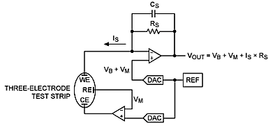
Counter Configuration (3 electrodes) Transimpedance Amplifier
![]()
Illustration taken from:
Both of these methods amplify the current produced by the reaction of glucose on the test strip and convert it to a voltage. The voltage is then fed into an Analog to Digital Converter and the digital signal is interpreted by the microcontroller, using a regression equation, to output a blood glucose concentration.
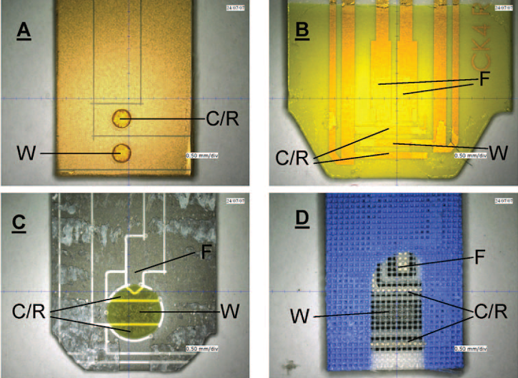
Below are some of the different electrode configurations in the reaction area (at the tip of the strip) used by different manufacturers.
![]()
Figure 4. Small volume electrochemical blood glucose monitoring strips with their top cover layer removed.
- W: Working Electrode
- C/R: Counter/Reference Electrodes
- F: Fill Detrection Electrode
- (A) BD test strip, with electrodes in recessed wells in an insulating layer.
- (B) Accuchek Aviva, its fill electrodes doubling as hematocrit-compensation electrodes.
- (C) Ascensia Contour.
- (D) Precision Xtra with electrodes covered by a mesh.
Figure 4. taken from:
- Heller A., Feldman B. Electrochemical glucose sensors and their applications in diabetes management. Chem Rev, 2008, 108:2482-2505.
-
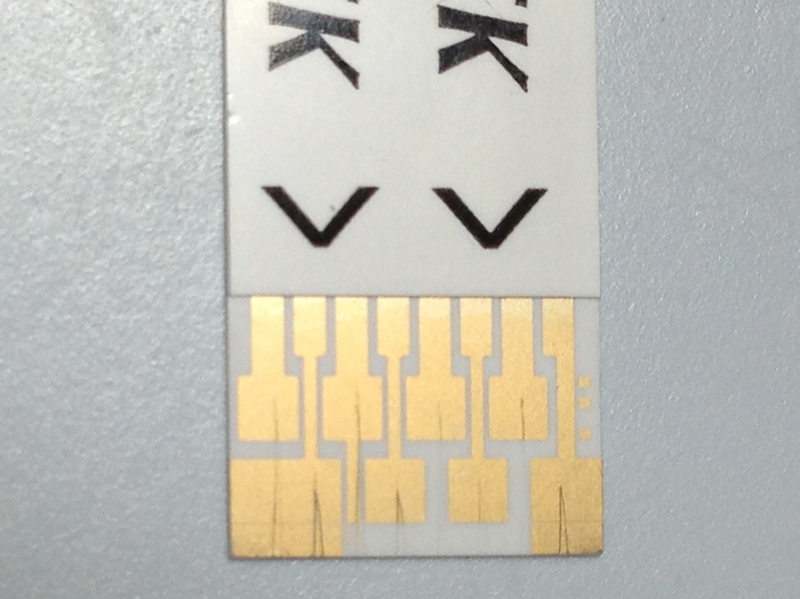
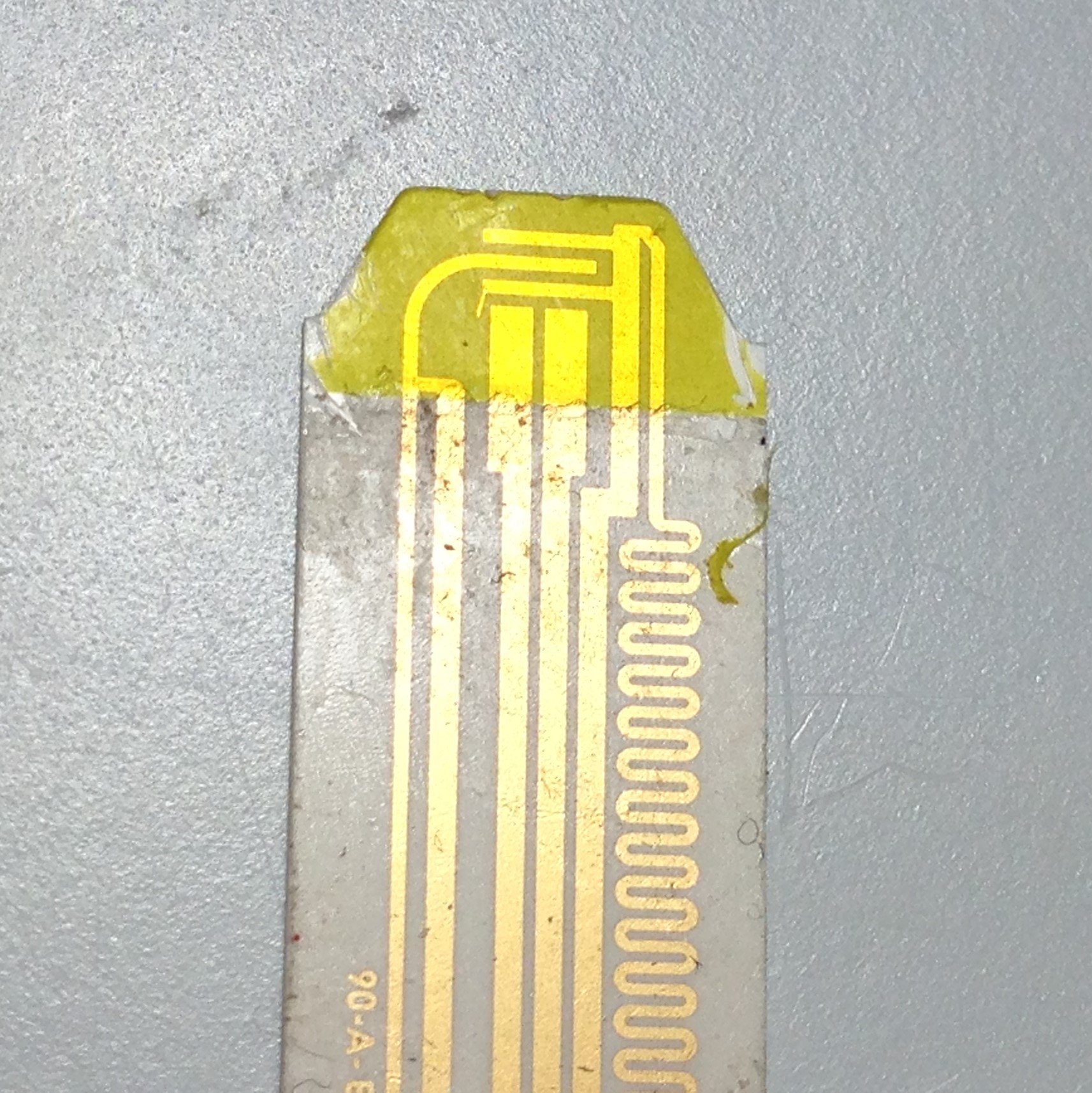
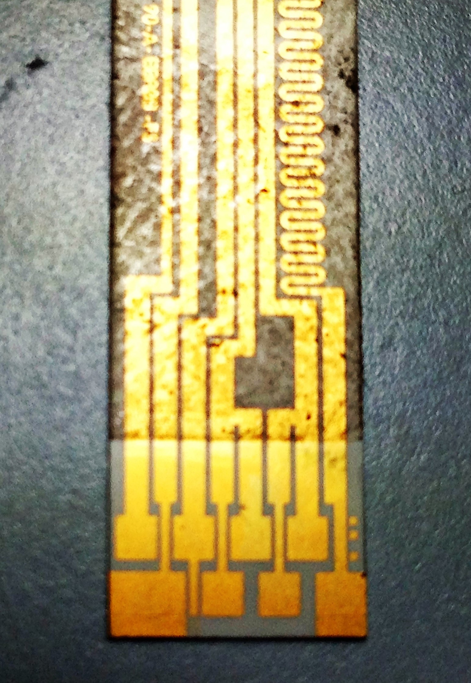
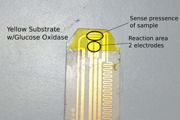
1st Strip Breakdown "Accucheck"
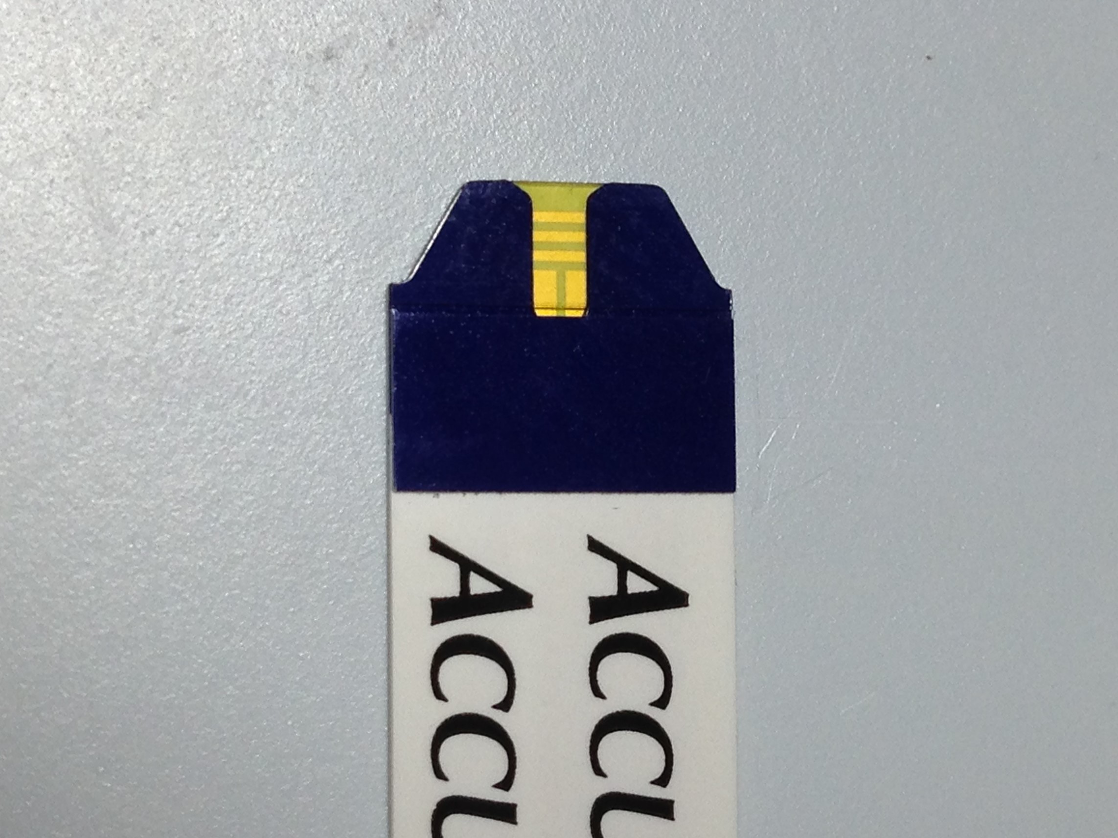
07/11/2016 at 05:30 • 0 commentsI was able to peel the layers apart on this strip fairly easily (no chemicals, just a razor blade to start)
Sample area:
![]()
Contact area:
![]()
Here it is after peeling layers off:
Sample area:
![]()
Contact area:
![]()
This is what I believe the circuit is:
Corrections are below the picture
![]()
**Sense electrodes are actually the Working and Counter Electrodes**
**Reaction electrodes are actually the Fill Detection Electrodes.**
Oops - my marked up version of the contact area is gone. Well, suffice to say this strip seems to be designed to used to electrodes - 1 active and 1 reference. There are 2 more electrodes for sensing when blood is applied to the strip. There are 8 contacts at the base of the strip, each of the 4 electrodes branches into 2 contacts. I'm not certain of the function of the serpentine route of the sense electrode on the right (it also has a solid straight track to the left of it) - I have some ideas but I'll need to test further.
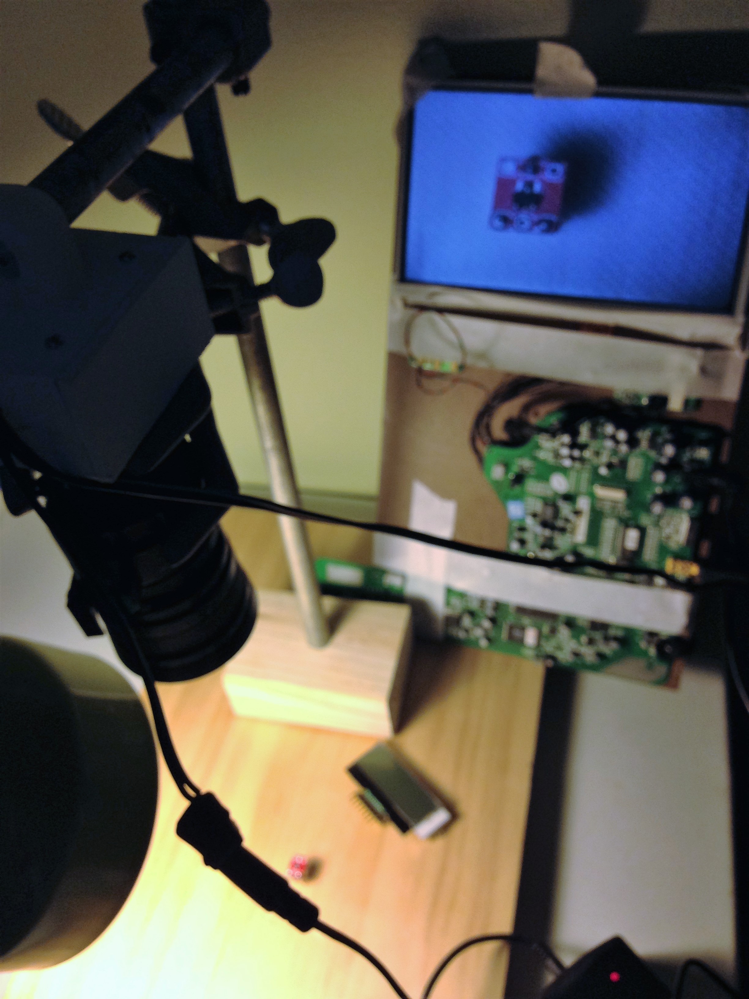
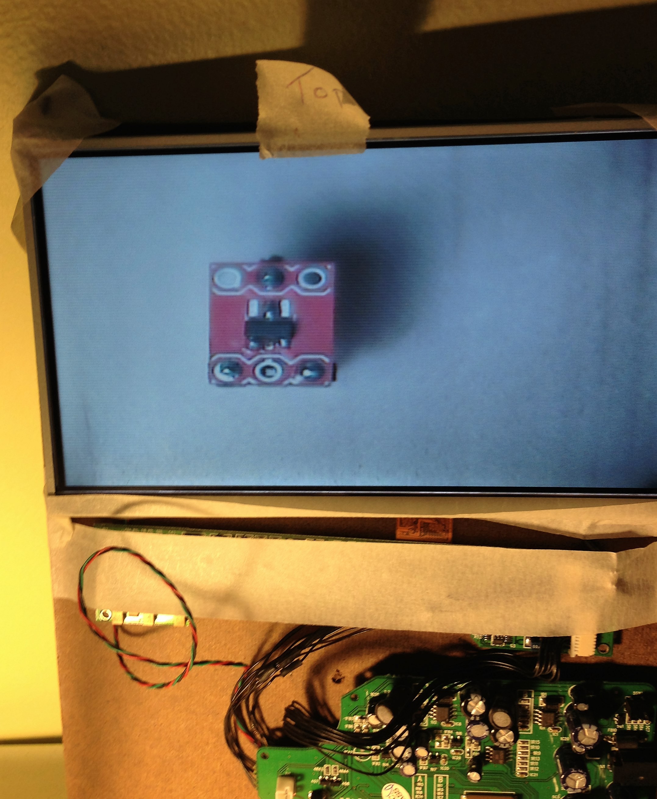
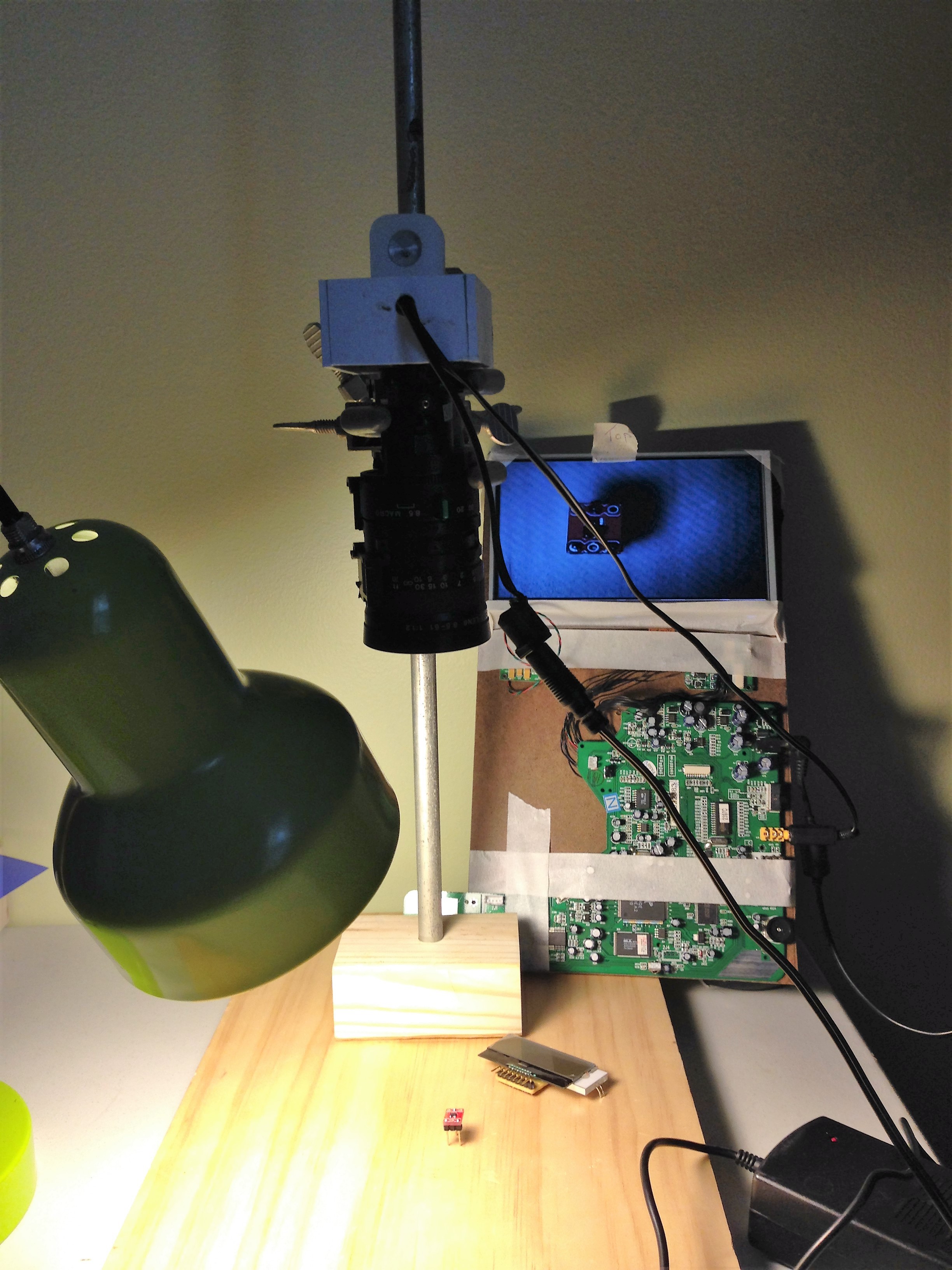
To help make the process of strip dissection easier (I've been using an inexpensive low power binocular microscope) I decided to hack together a video microscope. I looked at some projects involving USB camera but decided that I liked the idea of a composite security camera board (I've got a few from old projects - I've also got a few USB cameras). Some people complained that USB camera's didn't update in real time.
I cut a small box for the camera board, mounted it in there. Added an acrylic piece to the top of the box, with a 1/2" hole drilled through it, to accept a 1/2" rod. Lenses I took from optics I've saved from camcorders (other projects), and an old lcd screen pulled from a portable DVD player. In the end I came up with this:
![]()
![]()
![]()
It's not pretty (right now) but it achieves fairly good magnification and should make it much easier to look at strips.
-
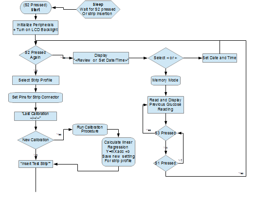
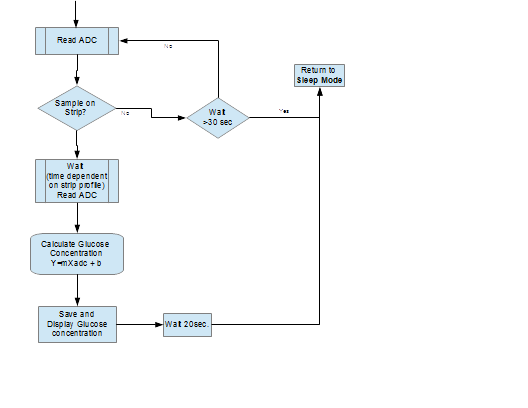
Software Flowchart
07/11/2016 at 04:21 • 0 commentsThis is my initial Flow Chart for how I want the meter to function. I'm still working out a number of details:
- Contact selection for different strips
- Working on a list of strip pin-outs (really "contact-outs")
- Type of configuration for each type of strip
- I'll cover details of this in my next post.
- Pin selections for different strips
- Since strips have different contact orientations and different arrangements of electrodes used for glucose measurement (I will cover this in greater detail in a future post - here or on my blog)
- Some use 1 reference and 1 active
- Others use 1 reference, 1 active and 1 counter
- (there may be others, but I haven't seen them yet)
- This means some strips may need to utilize additional Op-Amps and ADC's to be able to read the strip
- Many strips also include additional sense electrodes to detect when blood first contacts the strip.
- Since strips have different contact orientations and different arrangements of electrodes used for glucose measurement (I will cover this in greater detail in a future post - here or on my blog)
![]()
![]()
Continuing work on software development (at present this is my biggest challenge, this is my first attempt at using PIC microcontrollers - which require a lot of digging through details in datasheets - in comparison the hardware design is fairly easy) as well as deconstructing commercial strips to determine layouts of contacts and configuration of test strips.
- Contact selection for different strips
Universal Glucometer
Did your test strips just get more expensive? Has the drug store run out of strips for YOUR meter? Like to be able to use any test strip?