 Yann Guidon / YGDES
The multiply/divide mode of operation will require a multi-cycles sequence, hence some scheduling. I think I know how to make the logic part but... where does it get the synchronisation signals from ?
In the quare-root relay calculator, the sequences are generated with an electric motor and a cam. I don't want this. My best bet so far is a ring oscillator (3 relays?) with very large capacitors (I got that in stock, 15000µF is easy to find anyway).
Start/stop is as easy as inserting a SPDT in the ring to stick one coil to 0V for example. Once the start pulse is sent, this relay should be latched and the ring starts to oscillate. The "end condition" will release the control relay which will open the ring.
Easy.
In theory.
Yes I know, I should have googled that question before posting here. Shame on me.
Only one relay is necessary but a large capacitor is needed (2200µF?) and I'll need other relays (in series with the output ?) to drive the bunch of other coils to control.
I'm so lazy to make the diagrams though :-/
Now that's a good hint:
This "relaxation" version short-circuits its own coil, bad idea. But it gives me another idea ;-)
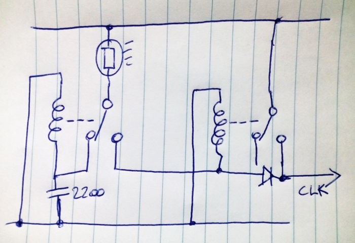
It could work...
- The lamp acts as a more or less permanent resistor to reduce inrush current (since it's mostly on)
- the capacitor acts as the reservoir, which makes a RC cell with the coil's resistance
- no need of a diode on the left relay because the large capacitor should handle the spike (if ESR is low)
- the right-hand relay acts as "buffer", its own coil's freewheel spike is reinjected in the slave coils (but who gets to dissipate the many slave coils' current ?)
Now, the trick of reinjecting spikes in other coils gets... interesting. Is it going to be a new sport/puzzle/game of this project ? :-)
Update : see Bad vibes
Discussions
Become a Hackaday.io Member
Create an account to leave a comment. Already have an account? Log In.
I made it! without any fake load!
It's only require 2 relays, 1 resistor,1 capacitor and an optocoupler...
maybe i post the schematic?
https://hackaday.io/page/9751-simplest-relay-low-freq-oscillator
Are you sure? yes | no
How about a PC fan motor with rear-earth magnets on the blades, spinning under a reed switch? :)
Are you sure? yes | no
hmmmm......
no :-)
Are you sure? yes | no
one relay, connect its coil through its Normally-Closed contacts == fun for the whole family and schoolyard, and an oscillator as well :)
Are you sure? yes | no
yep, that's the consensus I have found on the web :-D And this is what I have figured out with the above drawing.
Working with one technology makes you close-minded, I have been working with MOSFET, thus doing a ring oscillator sounded obvious...
Are you sure? yes | no