Yann Guidon / YGDES
-
Bislice
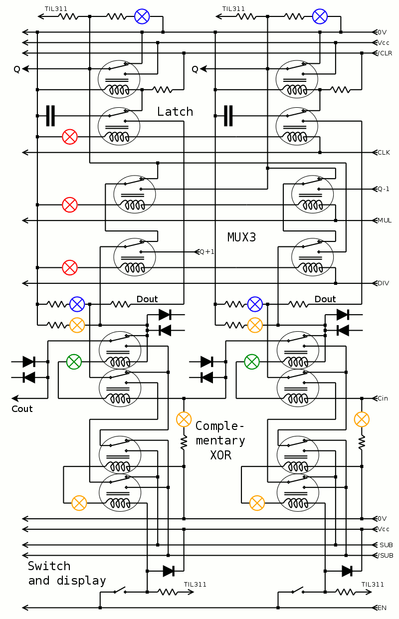
05/04/2016 at 09:31 • 0 commentsIt's getting insane but clearer...
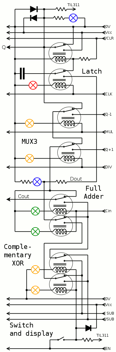
Connecting two slices from the precedent log gives the following diagram.
I've applied some changes I discussed earlier :
- control signals share a lamp with the adjacent bit
- the shifter/MUX3 gets cross-connected,
- I've moved some diodes close to the coils because they got separated by the MUX3.
No solution yet concerning the resistor-lamp pairs...
![]()
-
New slice
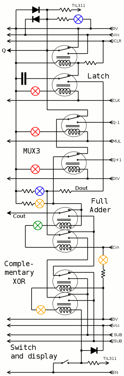
05/04/2016 at 08:32 • 0 commentsRealising that many relays are in parallel and amounted to DPDT, I have chosen to wire the coils in series, with one lamp instead of two per pair.
@jaromir.sukuba is not happy about the "savings", feeling that this reduce the Blinkenlichtheit of the circuit, but I actually added some missing lights for Cin for example.
I'm not happy with the many resistors for the lamps when they are not in series, they would drop each about 3V at 50mA, 150mW each... I might add another power rail (sinking, not sourcing) to reduce the losses. That would be at 2.5V and a diode must replace the resistor so it doesn't turn on when the level is 0V.
The CLK, MUL and DIV signals are shown as before but in reality, the relays are paired in series with adjacent bits, with only one lamp.
I have already an idea of the look with the colored lamps inbetween the round relays that form alveolas...
![]()
-
One bitslice
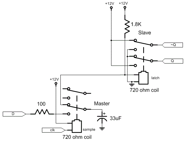
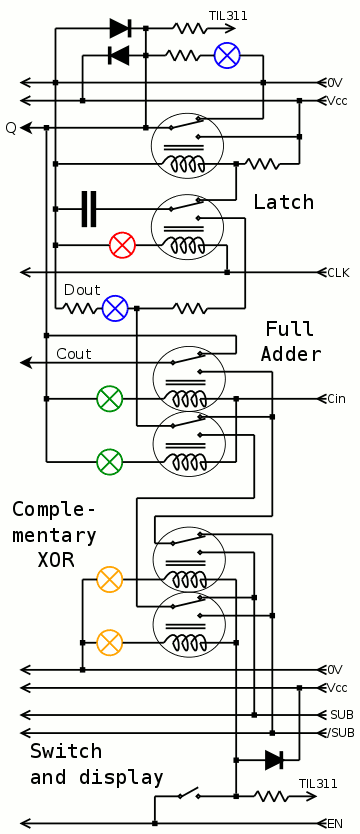
05/04/2016 at 04:57 • 0 commentsThe result of these last days of thinking is shown below, with a "simple accumulator" version.
![]()
I've been careful to connect the relays in ways that avoid long chains of contacts and overload of relays. For example, there is no direct path between any input and any output. This is essential for reliable computations.
It looks obvious now that DPDT relays would reduce the number of relays. This will be for another time, if any, but that's one of the lessons I learned. Maybe I could/should put relays in series to increase the voltage and reduce some losses and simplify things a bit but... meh.
One of the "innovations" (ahem) is the "complementary XOR" stage. Since I haven't found a simple, reliable way to remove one SPDT, I'm stuck with 6 relays at this stage. So I moved things around and came to this version where the complementary value of the switch is provided, inverted by the SUB signal (and its new companion /SUB).
The advantage is that the carry is garanteed to only affect one (pair of) relay, and the CDP (critical datapath) is as short as possible. You never know.
I've added color-coded lamps:
- yellow for input
- blue for results
- green for intermediary values (in series with the coil for more blinkenlightung and some power saving)
- red for control signals
Obviously absent from the above is the Left/Right shift in the feedback path but that's just 2 more relays. It seems I won't have enough greens or reds but... damnit. I'll use yellows instead for the MUX, as one of them will be ON as a single row, no confusion is possible.
![]()
(updated to add the /CLR signal)
Another interesting aspect is the freewheel diodes : only one is needed in the switch part because the current goes only in one direction. The "bussed" control signals (EN, SUB, /SUB, DIV, MUL, CLK, /CLR) can have a single diode, in parallel with a small capacitor for filtering. This leaves the coils of the full adder to protect with a full-bridge diode circuit (this is not shown on the above diagram). So overall, the cost in diodes is reasonable and the operation can be almost quiet (EMI-wise).
Next on the list : characterise the couple lamp/relayin series to find the best power supply voltage, and find which series resistance is best for the latch.
I could also put all the coils of a nibble in series and have 10V control signals for DIV, MUL and CLK, which would save some lamps... The lamps are given for 3V and the relays can do 2.8V so (2.8×4)+3=14.2V max. A 12V PSU could work because latch is at 2V (=>10V). A cap in parallel with the lamp would provide another kick.
-
Faster ripple
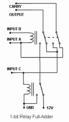
05/03/2016 at 11:17 • 0 commentsLooking again at the full adder circuit, there are 3 SPDT relays (the DPDT relay counts as two SPDT)
![]()
The "critical datapath" goes through C, which has an inverter (implemented by the bottom relay). This means that C should be the input connected to the switches and not a carry input. Then the problem is to "regenerate" the Carry signal because the chain can be quite long and would overload one relay. So ideally the carry out goes to input B, while input A comes from the flip-flop.
(drawing To Be Drawn)
-
Save the relays !
05/03/2016 at 04:19 • 2 commentsSo my last estimate made me realise that 200 relays is barely enough.
Actually these relays are sold by 36 or 72 and the estimate exceeds 192 relays. Which is the number I've already ordered. And I've already ripped one apart to make the cool cover picture. And I can't make a "slice" prototype AND the final unit so I'm in a bad position (and broke, btw). And I can't accept to reduce the width. And time is running out for the submission to the prize in a few weeks. I need money AND time because things are accelerating now. I'm caught in the evil spiral of fun turning into madness (thank you @Adam Fabio ;-P)
But there might be a tiny bit of relief. Because while trying to finally sleep, my mind wandered across the overall design and I realised something. I can save 16 relays ! This won't solve everything and world hunger but it will save my pride.
Remember the slice of ALU: it starts with the rotary switch and the XORs.
The switch's common is tied to +Vcc (this sounds pretty normal and obvious). Then I realised I could "add 0" for the multiplication with a little trick, that is : turn the current off. No current in the relay, no activation, great.
But now I'm going further and I can propagate the XOR function to the switchs' common pin: what if the whole signal/rail was switched from +Vcc to 0V ? That would do the inversion, for all the signals ! (it would probably save 1A as well).
Let's go back to the diagram of the full adder:
![]() Input C is tied to one coil and one out of 2 outputs.
Input C is tied to one coil and one out of 2 outputs.Input A is tied to one coil and one output.
Input B is tied only to one end of a coil so this is the signal that must be connected to the rotary switches. This way, A and C can still work properly even if there is no current. Actually I suppose it could work as well but this choice preserves some design principles/assumptions.
Wait, this doesn't work. First, the TIL311 is harder to drive because when the switch is off, there is voltage that goes through the paralleled coils of the A-B gate. Diodes and transistors do not easily solve this situation.
Worse: when the SUB signal is grounded, the function of the switch does not change the actual logical function.
The XOR relay makes everything simpler...
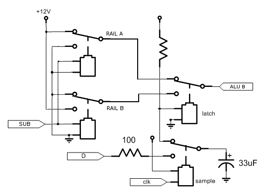
Looking at the larger picture, though, something else appears.
The other input comes from the accumulator, which is made of a relay.
Notice how the coil is not tied to the output (unlike the classical methods). The output can be anything we want so we could (selectively) swap the Vcc and GND rails, which would end up as inverted values on the A or B signal of the full adder.![]()
It will make reading the output more complex on the TIL311 but the SUB signal would be restored to 'normal' (low) at the end of an operation. The inconvenience could be further reduced by using the "Latch Enable" pin of the TIL311 so the display doesn't change during computations.
![]()
(The two SPDT on the left are common to the 16 FF of the accumulator)
I have somewhat factored the original XOR relays into 2 relays (DPDT), but I haven't yet tested everything.
Subtraction is not commutative so my clever trick is not only clumsy but also useless. I should go back to sleep and buy more relays !
Subtraction is not commutative, yet addition is and the order of the 3 inputs A, B and C don't matter. So it shoudln't even matter which input is inverted. I'm confused. I just give up and return to the original XOR design, which has none of the above problems and lets us easily see the values on the TIL311.
Actually I'm even doing a double XOR to provide the complementary value, as explained in Faster ripple.
-
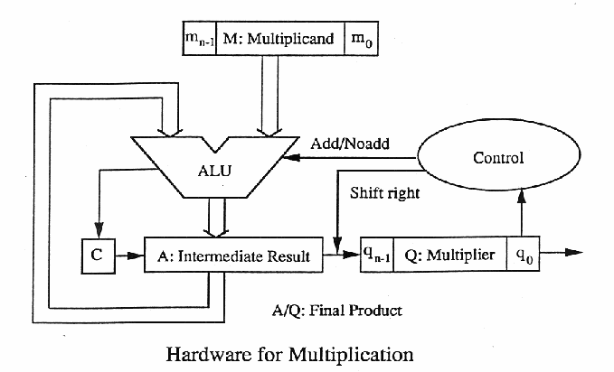
Multiplication and Division
05/02/2016 at 22:45 • 0 commentsThe circuits that perform addition and subtraction can be reused in the circuits shown in this page : http://fourier.eng.hmc.edu/e85_old/lectures/arithmetic_html/node8.html
Multiplication and division require a shift register that is large enough to store the product or dividend. In the case of multiplication, I tried to redesign it in my head but I stumbled on the problem of the carry... The below drawing (taken from the link above) solves it finally :-)
For a 16-bits multiplicand, the shift register needs 32 bits. The carry counts as a 33rd but it does not remain set at the end, at least for the unsigned multiplication. The maximal value is 0xFFFF×0xFFFF=0xFFFE0001![]()
The multiplier should be loaded from the input so a row of relays is required to select the source of the input data. The accumulator (and carry) is cleared initially but another line of 16 relays must multiplex the accumulator's value to perform the shift, because in the add/sub mode, the accumulator is not shifted.
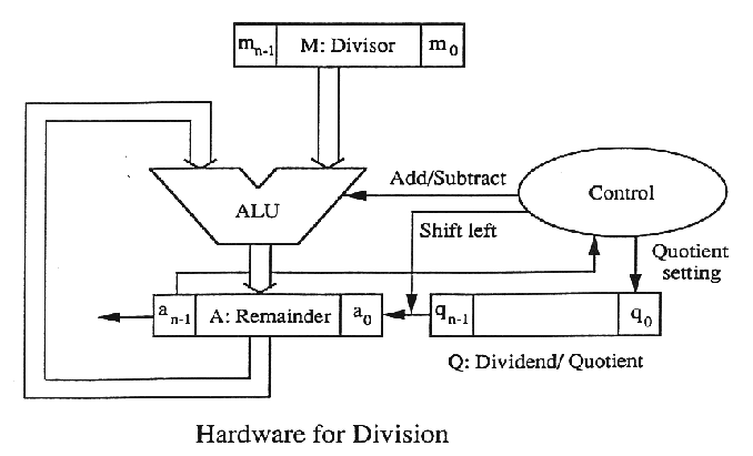
Division looks almost the same, but there's a catch.
![]()
The shift direction is reversed ! So that's 32 more MUXing relays ! (and 2A of consumption)
I have not yet decided if I'll implement restoring or non-restoring division. Both are possible because I can either add 0 or add/subtract at will, it's just a different control signal to toggle.
Overall, that's 64 relays for MUXing and 64 relays for the 32-bits shift register. 128 relays are added to perform the 4 operations. The ALU is 4×16=64 relays already, 192 relays are needed and I don't even count the control logic or the amplifiers !
-
Signed or unsigned ?
05/02/2016 at 22:33 • 2 commentsFor the sake of simplicity, we'll consider that this machine only handles unsigned numbers.
For the addition and subtraction, this does not matter because 2s-complement representation is insensitive to the actual circuit. It's then just a matter of how we interpret the Most Significant Bit, and display the input and output numbers.
Considering that the #DYPLED is not yet ready and I'll be using TIL311s in hexadecimal, it just makes sense to say the numbers are positive.
For division and multiplication, the hardware must know the signedness of the operands. Things can get pretty tricky and division has weird rounding behaviours. These considerations are better left to "advanced" machinery building projects...
-
A slice of ALU
05/01/2016 at 19:01 • 0 commentsFinally, a little overview of a "slice" of 4 bits.
This is convenient because 4 bits is the width of a TL311 input bus, it's the width of the hexadecimal rotary switch and ... a slice could be replicated "while supplies (of relays) last".
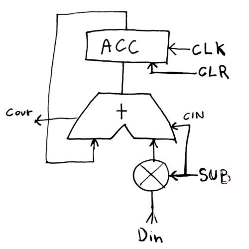
The overall system looks like this :
![]()
It performs add, subtract (thanks to the input inversion), stores a result in the accumulator, or clear it.
Not shown are the general control logic. TBDL (to be designed later, we can use buttons until it's properly figured out)
- The clock signal (CLK) comes from a button but later, from an oscillator.
- The CLR signal can actually be a relay that normally connects to +Vcc but switches it off when it receives a pulse. This will de-energize the relays and reset them.
- The SUB signal is GND when add (or "store") and +Vcc during subtraction.
- Din is the hexadecimal bus.
This will be changed a bit for multiplication and division but let's get +/- right first :-)
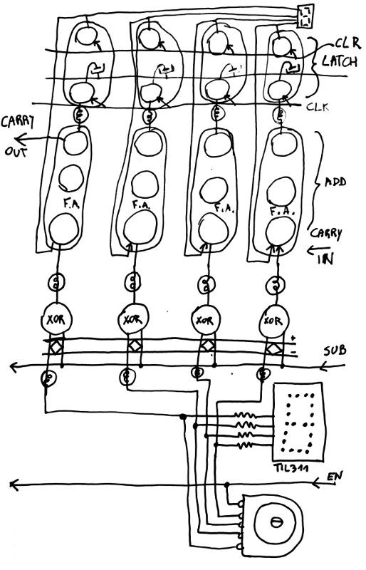
Translated into relays and a rough layout, we get something like this:
![]()
(I know, the drawing is a bit compressed at the top)
The lower part is the input with the hex switch and the TIL311 to display the number.
The 4 bits are lit and fed to a XOR (one relay, with a diode bridge at the input).
The nibble is fed to the adder, which is a chain of full adders (as covered in the rationale).
The other input comes from the DFF, (also covered in the rationale).
Load/spikes can be reduced if some relays are added to amplify the control signals
Things will get a bit more complex with the multiplies but no significant change is expected.
I should build an add/sub nibble (2 TIL311 and 24 relays) and then consider the multiplies, when all the easy details are polished... I'll also have a better estimate of the overall supply current.
-
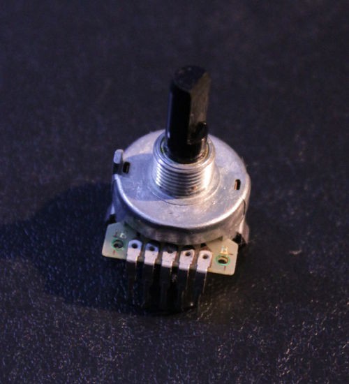
The hexadecimal rotary switches
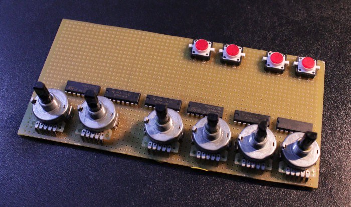
05/01/2016 at 18:02 • 0 commentsA series of rotary switches provides a rather convenient data input of addends.
This is an old eBay find and it's very handy !
![]()
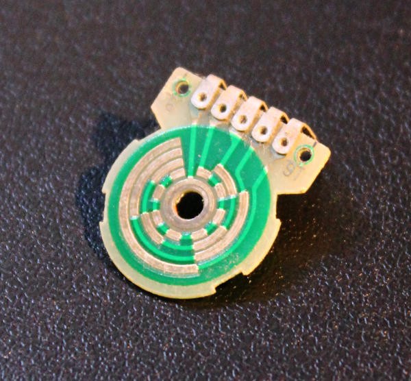
I've torn one apart to show the internal wiring, and it's a pretty simple binary encoder :-)
![]()
I've used some of these for the (semi-aborted) attempt at a front panel for the #Quick & Dirty Frequency Generator
![]()
For this project, though, there will be no mode push-buttons or bypass '595. TIL311 are perfect for the desired futuro-vintage look and feel of hexadecimality.
I'll keep the "one lamp in series with each coil" idea but it's good to visualise the hexadecimal value. I might create "slices" of 4 or 8 bits on the perforated proto board (I'll use bakelite for extra "oldtimer" feel).
-
A sick trick for the multiplies
05/01/2016 at 09:10 • 0 commentsThe algorithm for multiplication is pretty easy. If the multiplicand bit is set, add the multiplier to the shift register.
The initial idea was to use a MUX2 to select between the last result (shifted register) or the new result (oh, wait..... nevermind)
But that's typically an electronics-minded design.
Moving backwards, I realise that the multiplier is just a set of manual switches. They are either tied to +Vcc or left open.
Wait.
What if the +Vcc was left open too ? That would add nothing. Which is the desired behaviour for the multiplication by 0. Bingo !
So now, I saved a row of quite a lot of relays, just by routing the multiplicand bit to the +Vcc of the multiplier's rotary hex switches...
(schematics left as an exercise to the reader, or be patient, I must buy groceries...)
SPDT16: 16-bits arithmetic unit with relays
Let's imagine I could get about 200 SPDT relays. Of course I would know what to do with them :-D But will 200 be enough ?

 Input C is tied to one coil and one out of 2 outputs.