-
A pulser .. again
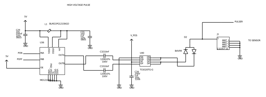
03/08/2018 at 22:42 • 0 commentsI was wondering why I couldn't get pulses on all negative... when the following design (from un0rick) works.
![]()
The reason is stupid.
1. When OE is high, Pon needs to go L->H during the pulse, but the second control is _inversed_: Poff needs to gow H->L during the damping period.
2. When OE is low, OutA is high (as if InA was high) and OutB is low (as if InB was low).
Hence, when two TC6320 were used, as in alt.tbo first of the name:
- Pulser side: InA is right, but InB needs to be high by default.
- Damper side: OE activates or desactivates the damper... but it doesn't do anything! With OE high or low, the output is the same...
Well well well.. alt.tbo can still be used with HVPos at 25 to 75V, but then HVNeg has to be set to GND. And then, PPoson has to be on L->H, whereas the damper is activated by PNeg going H->L. Unipolar, but working!
-
More experiments - and a new driver
10/01/2017 at 14:32 • 0 comments -
New bipolar, high voltage ultrasound pulser module
09/30/2017 at 17:31 • 0 commentsI've been making progress for the alternative pulser, here on github, based on MD1213 and TC6320.
It does look nice, with jumpers to select voltage levels, as well as easier connectors:
![]()
It seems the first pulses are up to the task: 25, 50, and 75V have different echoes strengths!
![]()
Soon to be on Tindie for the first batch - twice the HV possibilities, same price as the first module!
-
Making a cheaper pulser
08/30/2017 at 19:44 • 0 commentsPart of this project is a pulser module - its aim being to generate the high voltage necessary to generate the inital accoustic wave for ultrasound imaging, with severe constraints in terms of voltage, impendance, and duration. 100V for 150ns are not unheard of.
The previous module, tobo, was great at its job, up to two point. First was its price, with a 50$ RECOM component to generate the high voltage, and then the possibly more fragile components such as the HV7360.
To solve this, the HV7360 has been replaced, and I'm changing this unipolar pulser to a bipolar pulser, for both precise timing of pulses at 0, +-25V, +-50, +-75V -- voltages being set with jumper. The layout still remains the same, and yields:
![]()
It's been sent to Shenzen, let's see how it goes =)
-
Ultrasound with the Pi W 24Msps ADC
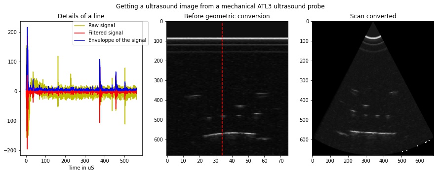
07/16/2017 at 22:22 • 0 commentsand getting access to ultrasound raw signals, yields the way to more fun with ultrasounds! The ATL3 probe used provided access to interesting insights and signals, ultimately to rebuild an ultrasound image of our beloved phantom( as usual the jupyter notebook is available):
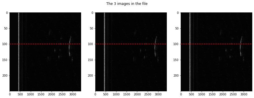
![]() Not too bad! We have 1k lines, 2500points on each ADC, times 2 ADCs. That's around 5M points, at a resulting 24Msps. I got three images:
Not too bad! We have 1k lines, 2500points on each ADC, times 2 ADCs. That's around 5M points, at a resulting 24Msps. I got three images:![]() Which, combined, provide a good example of an ultrasound image:
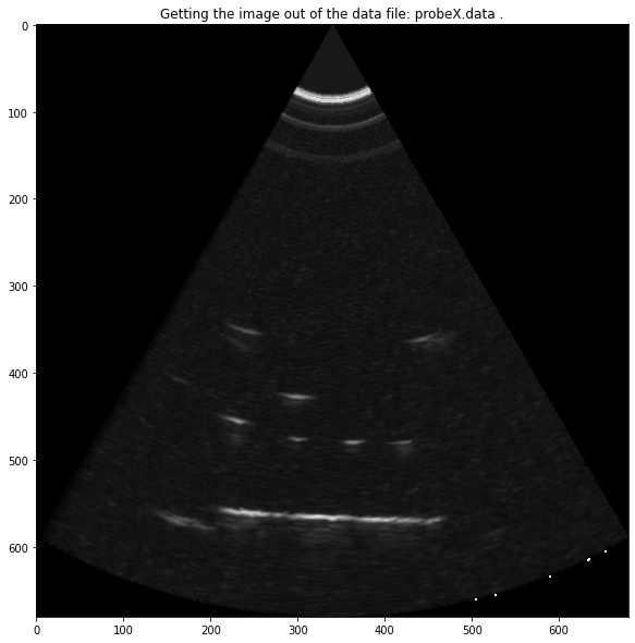
Which, combined, provide a good example of an ultrasound image:![]() yeahh!!
yeahh!! -
Getting to signal processing
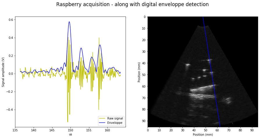
07/02/2017 at 09:15 • 0 commentsGot interesting images using both the analog envelope and the digital detection of the envelope processes. Digital envelope detection detailed at https://github.com/kelu124/echomods/blob/master/elmo/data/arduinoffset/20170612-ArduinoFFTed.ipynb yields the following
![]()
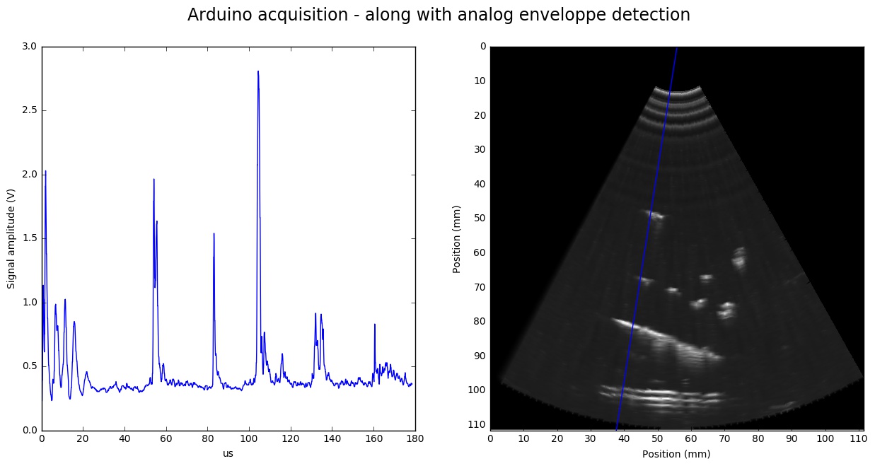
and on the analog envelope side (see jupyter notebook too):
![]()
-
Putting it all together
06/11/2017 at 22:28 • 0 commentsexI have tried with the latest 20Msps ADC pHAT I've assembled for the device. I've butchered soldering the 2nd ADC, and had no spare, so I skipped one of those. The issue in this is that I got 2 output pins of the ADC soldered together, so it outputs rubbish...
Long story short.. here's my setup:
![]()
and the output..![]()
All of this is managed through the Raspberry, so I'm quite excited, and eager to develop the API to expose proper data from the RPi through wireless interactions!
-
Raspberry Pi setup
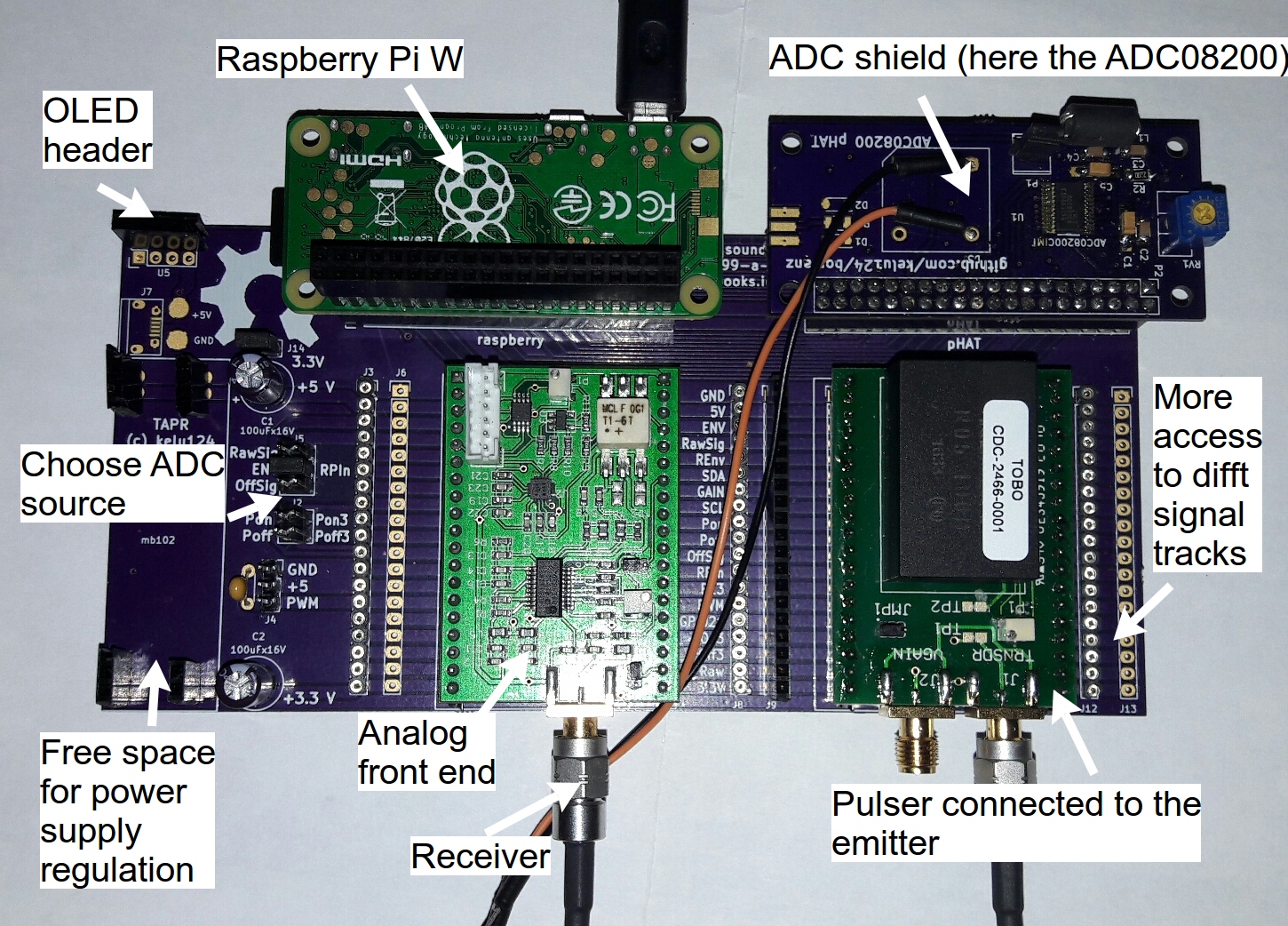
05/29/2017 at 19:54 • 0 commentsHere's a tentative setup for the SDK. It's based on a motherboard exposing all interesting signals, a Pi (W in this case), an ADC shield (detailed here) which goes up to 10/11Msps, and the pulser as well as analog processing modules.
Things to do now:
- Exposing the Pi IP on the OLED on standy
- Documentation as a webserver by the Pi
- Web storage also through a webserver (in addition to the Pi SSH)
- Getting a nicer ADC pHAT ... 20Msps on its way
- Making the kernel module better (control of the pulse duration for ex - and getting additional infos if possible)
- Doing a python server - acting to serve the signal through a dedicated API
- Explore if additional pins can really be exposed through the pads.. and used.
![]()
Beware, I had to use a 750mA 5V power supply for the USB power. It does use a tad of power as is! -
Simplifying the ultrasound imaging debugger
05/11/2017 at 20:05 • 0 commentsLots of water under the bridge. Since the last post! This project was born a year ago when I wanted to split a bigger board into smaller modules. I went on exploring different options, combination of modules, hardware, probes, motors, and DAQ (from STM32s to Beaglebone PRUDAQ, passing through onboard smaller ADCs), which yielded lots of interesting results. I really enjoyed exploring all of this, and really learnt a lot. Who know I'd do this when 18 months ago I didn't know anything about electronics hardware (or at least had forgotten all from the golden age of my studies?).
Anyhow, the goal here is simple. I need a "exploring tool" to explore ultrasound systems. I have built several versions with Murgen, and have made the proof that it's possible to have a small ultrasound machine in your garage. However, I found more pleasure in building the tools and in the process of digging into the different components.. and that's what I want to explore in this project.
Hardware is basically already built: previous lessons from Murgen bring the analog front end, a hack I have can be used to emulate a probe: what remains is to remove overkills on the circuits, and SIMPLIFY everything, making it more robust and more user friendly.
The second step will be to have a good driver for the Raspberry Pi (which I believe is enough for my needs), to control the hardware, and develop a good enough server API.
Once this is done, I'll be happy to test it with probes like the ATL probes I've been debugging, with doppler probes projects here and also to explore this chinese probe of mine.
So, on with this project, and see if cross-pollination works =)
-
A first module: the analog front end
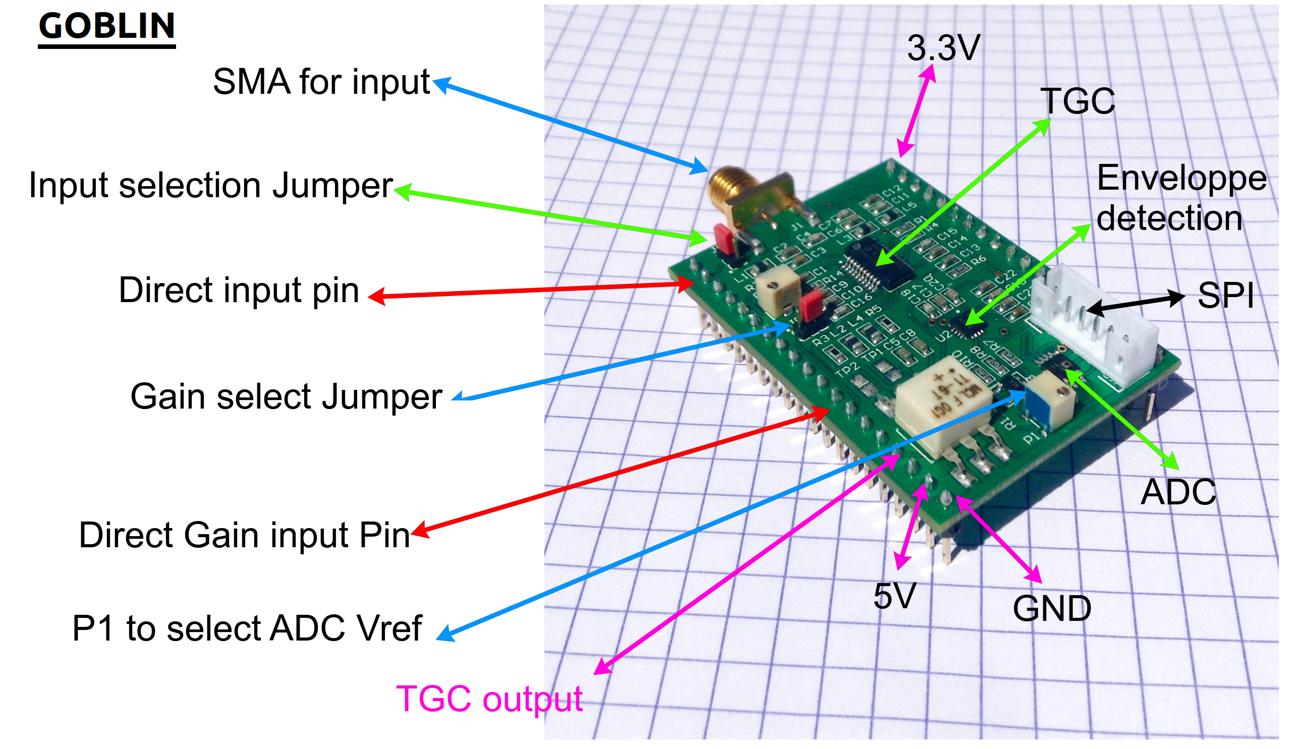
07/10/2016 at 11:38 • 0 commentsbGoblin is born! We received the module from the fab today. This small module is composed of:
- A time-gain-control (or a VGA) to compensate for the ultrasound attenuation
- An enveloppe detector, to actually get the echoes
- An amp to better stretch the signal before it goes to the...
- 3Msps ADC
![]()
How does it work?
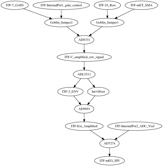
![]() Which, in functional blocks, gives:
Which, in functional blocks, gives:![]() It works! Let's try it with a 3MHz burst:
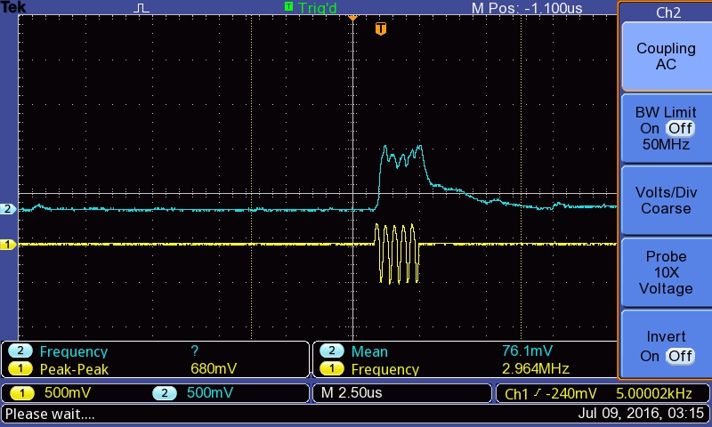
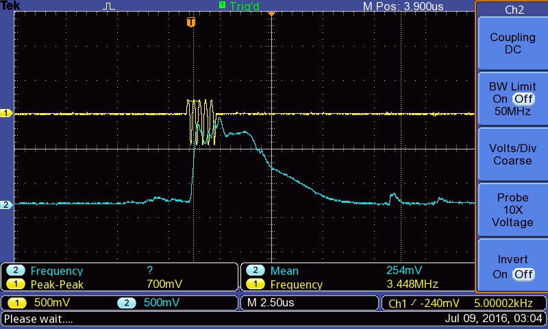
It works! Let's try it with a 3MHz burst:
Or, if we buff up the signal: with the gain control, to make it better "readable" with the ADC:
A HSDK for ultrasound imaging
Using a Raspberry-based hardware and software development kit to understand ultrasound imaging
 kelu124


 Not too bad! We have 1k lines, 2500points on each ADC, times 2 ADCs. That's around 5M points, at a resulting 24Msps. I got three images:
 Which, combined, provide a good example of an ultrasound image:
 yeahh!!


 Which, in functional blocks, gives:
 It works! Let's try it with a 3MHz burst: